EP0559566A1 - Locking device for a rectilinear movement mechanical actuator, incorporating an inertia safety locking member - Google Patents
Locking device for a rectilinear movement mechanical actuator, incorporating an inertia safety locking member Download PDFInfo
- Publication number
- EP0559566A1 EP0559566A1 EP93400562A EP93400562A EP0559566A1 EP 0559566 A1 EP0559566 A1 EP 0559566A1 EP 93400562 A EP93400562 A EP 93400562A EP 93400562 A EP93400562 A EP 93400562A EP 0559566 A1 EP0559566 A1 EP 0559566A1
- Authority
- EP
- European Patent Office
- Prior art keywords
- rod
- housing
- roller
- seat
- locking device
- Prior art date
- Legal status (The legal status is an assumption and is not a legal conclusion. Google has not performed a legal analysis and makes no representation as to the accuracy of the status listed.)
- Granted
Links
Images


Classifications
-
- B—PERFORMING OPERATIONS; TRANSPORTING
- B60—VEHICLES IN GENERAL
- B60N—SEATS SPECIALLY ADAPTED FOR VEHICLES; VEHICLE PASSENGER ACCOMMODATION NOT OTHERWISE PROVIDED FOR
- B60N2/00—Seats specially adapted for vehicles; Arrangement or mounting of seats in vehicles
- B60N2/24—Seats specially adapted for vehicles; Arrangement or mounting of seats in vehicles for particular purposes or particular vehicles
- B60N2/42—Seats specially adapted for vehicles; Arrangement or mounting of seats in vehicles for particular purposes or particular vehicles the seat constructed to protect the occupant from the effect of abnormal g-forces, e.g. crash or safety seats
- B60N2/433—Safety locks for back-rests, e.g. with locking bars activated by inertia
-
- B—PERFORMING OPERATIONS; TRANSPORTING
- B60—VEHICLES IN GENERAL
- B60N—SEATS SPECIALLY ADAPTED FOR VEHICLES; VEHICLE PASSENGER ACCOMMODATION NOT OTHERWISE PROVIDED FOR
- B60N2/00—Seats specially adapted for vehicles; Arrangement or mounting of seats in vehicles
- B60N2/02—Seats specially adapted for vehicles; Arrangement or mounting of seats in vehicles the seat or part thereof being movable, e.g. adjustable
- B60N2/22—Seats specially adapted for vehicles; Arrangement or mounting of seats in vehicles the seat or part thereof being movable, e.g. adjustable the back-rest being adjustable
- B60N2/23—Seats specially adapted for vehicles; Arrangement or mounting of seats in vehicles the seat or part thereof being movable, e.g. adjustable the back-rest being adjustable by linear actuators, e.g. linear screw mechanisms
-
- B—PERFORMING OPERATIONS; TRANSPORTING
- B60—VEHICLES IN GENERAL
- B60N—SEATS SPECIALLY ADAPTED FOR VEHICLES; VEHICLE PASSENGER ACCOMMODATION NOT OTHERWISE PROVIDED FOR
- B60N2/00—Seats specially adapted for vehicles; Arrangement or mounting of seats in vehicles
- B60N2/90—Details or parts not otherwise provided for
- B60N2/919—Positioning and locking mechanisms
- B60N2/929—Positioning and locking mechanisms linear
-
- Y—GENERAL TAGGING OF NEW TECHNOLOGICAL DEVELOPMENTS; GENERAL TAGGING OF CROSS-SECTIONAL TECHNOLOGIES SPANNING OVER SEVERAL SECTIONS OF THE IPC; TECHNICAL SUBJECTS COVERED BY FORMER USPC CROSS-REFERENCE ART COLLECTIONS [XRACs] AND DIGESTS
- Y10—TECHNICAL SUBJECTS COVERED BY FORMER USPC
- Y10T—TECHNICAL SUBJECTS COVERED BY FORMER US CLASSIFICATION
- Y10T74/00—Machine element or mechanism
- Y10T74/20—Control lever and linkage systems
- Y10T74/20576—Elements
- Y10T74/20636—Detents
- Y10T74/2066—Friction
-
- Y—GENERAL TAGGING OF NEW TECHNOLOGICAL DEVELOPMENTS; GENERAL TAGGING OF CROSS-SECTIONAL TECHNOLOGIES SPANNING OVER SEVERAL SECTIONS OF THE IPC; TECHNICAL SUBJECTS COVERED BY FORMER USPC CROSS-REFERENCE ART COLLECTIONS [XRACs] AND DIGESTS
- Y10—TECHNICAL SUBJECTS COVERED BY FORMER USPC
- Y10T—TECHNICAL SUBJECTS COVERED BY FORMER US CLASSIFICATION
- Y10T74/00—Machine element or mechanism
- Y10T74/21—Elements
- Y10T74/2101—Cams
- Y10T74/2107—Follower
Abstract
Description
La présente invention a pour objet un dispositif de blocage de vérins mécaniques à déplacement rectiligne, incorporant un organe de blocage de sécurité par inertie, ces vérins mécaniques étant plus spécialement utilisés dans des sièges de véhicules terrestres, nautiques ou aériens, soit pour régler l'inclinaison du dossier, soit pour régler en hauteur ou d'avant en arrière l'assise du siège considéré.The subject of the present invention is a device for blocking mechanical cylinders with rectilinear movement, incorporating a safety blocking device by inertia, these mechanical cylinders being more especially used in seats of land, nautical or air vehicles, either for adjusting the inclination of the backrest, either to adjust the height or front to back of the seat.
On connaît en particulier par FR-A-2 652 129, un dispositif de blocage de vérins mécaniques du type susmentionné mais il est apparu que les constructeurs, incorporant ces sièges dans des véhicules divers, désiraient que ces mécanismes soient munis d'un organe de blocage de sécurité complémentaire dans le cas où, soit par fausse manoeuvre, soit par inattention, le dispositif de blocage du vérin considéré, n'étant pas parfaitement enclenché, le vérin soit bloqué automatiquement par inertie lorsqu'il se produit un choc quelconque latéral, d'avant ou d'arrière.In particular, FR-A-2 652 129 discloses a device for blocking mechanical jacks of the aforementioned type, but it has become apparent that the manufacturers, incorporating these seats in various vehicles, wanted these mechanisms to be provided with a additional safety blocking in the event that, either by false operation or by carelessness, the cylinder blocking device considered, not being fully engaged, the cylinder is blocked automatically by inertia when any lateral impact occurs, front or rear.
Il est nécessaire d'avoir une sécurité permettant le blocage instantané de la tige de vérin par rapport au boîtier lorsqu'il y a un choc. En effet, il peut se produire, lors d'un freinage brutal du véhicule considéré, que le ou les vérins de réglage d'un des sièges soient libres et donc soit le dossier, soit l'assise puisse se déplacer avec une projection dont la vitesse est égale à la vitesse initiale du véhicule provoquant ainsi un accident grave pour le passager assis sur le siège considéré.It is necessary to have a security allowing instantaneous blocking of the jack rod relative to the housing when there is a shock. In fact, it may happen, during sudden braking of the vehicle in question, that the adjustment cylinder (s) of one of the seats are free and therefore either the backrest or the seat can move with a projection whose speed is equal to the initial speed of the vehicle, thus causing a serious accident for the passenger seated in the seat concerned.
La présente invention remédie à ces inconvénients en équipant chaque vérin mécanique non seulement d'un dispositif de blocage normal mais également d'un organe de blocage de sécurité par inertie.The present invention overcomes these drawbacks by equipping each mechanical cylinder not only with a normal blocking device but also with a safety blocking device by inertia.
De plus, il est également prévu, en plus d'un organe de blocage de sécurité par inertie, un dispositif dont l'organe de blocage de sécurité est entraîné par une masse pendulaire agissant lorsque le débattement dépasse au moins 30° par rapport à la verticale définie par l'axe de la masse pendulaire.In addition, there is also provided, in addition to a safety blocking device by inertia, a device whose safety blocking member is driven by a pendulum mass acting when the clearance exceeds at least 30 ° relative to the vertical defined by the axis of the pendulum mass.
Pour finir, il est prévu également, en plus du dispositif muni d'un organe de blocage de sécurité par inertie avec masselotte, un organe mémoire de position qui permet d'utiliser ces sièges dans des véhicules à deux portes afin de permettre, par un mouvement rapide, le dégagement d'un siège avant soit pour la sortie soit pour l'entrée des passagers sur les sièges arrière.Finally, there is also provided, in addition to the device provided with an inertia safety blocking member with counterweight, a position memory member which makes it possible to use these seats in vehicles with two doors in order to allow, by a rapid movement, the release of a front seat either for the exit or for the entry of passengers in the rear seats.
Conformément à l'invention, le dispositif de blocage de vérins mécaniques à déplacement rectiligne dans lequel au moins une tige est normalement bloquée par des galets crantés coopérant avec des rampes dentées de grains en V, guidés par un boîtier interne de forme polygonale dont une partie inférieure sert de support à la tige, le déplacement des grains vers le bas provoquant un blocage et, vers le haut, un déblocage, est caractérisé en ce que la partie inférieure du boîtier intérieur présente deux rampes inclinées qui coopèrent avec un galet strié placé sous la face inférieure de la tige, ce galet strié sous l'effet de l'inertie venant se bloquer, lors d'un choc, sous la tige en montant soit le long de la rampe amont, soit le long de la rampe aval.In accordance with the invention, the device for blocking mechanical cylinders with rectilinear movement in which at least one rod is normally blocked by notched rollers cooperating with toothed ramps of V-shaped grains, guided by an internal housing of polygonal shape, part of which lower serves as a support for the rod, the displacement of the grains down causing blocking and, upward, unblocking, is characterized in that the lower part of the inner housing has two inclined ramps which cooperate with a striated roller placed under the underside of the rod, this striated roller under the effect of inertia coming to block, during an impact, under the rod while climbing either along the upstream ramp, or along the downstream ramp.
Suivant une autre caractéristique de l'invention, la came de blocage, coopérant avec les galets, est montée sur un arbre portant extérieurement une pièce pendulaire terminée à sa partie inférieure par une masselotte, la pièce pendulaire présentant, dans sa partie intermédiaire, une fenêtre destinée à coopérer avec l'axe du galet denté roulant sur des pans inclinés dentés pour bloquer, lors d'un choc, la barre sur le boîtier contenant le mécanisme.According to another characteristic of the invention, the locking cam, cooperating with the rollers, is mounted on a shaft carrying externally a pendulum part terminated at its lower part by a counterweight, the pendulum part having, in its intermediate part, a window intended to cooperate with the axis of the toothed roller rolling on inclined toothed faces to block, during a shock, the bar on the box containing the mechanism.
Diverses autres caractéristiques de l'invention ressortent d'ailleurs de la description détaillée qui suit.Various other characteristics of the invention will also emerge from the detailed description which follows.
Des formes de réalisation de l'objet de l'invention sont représentées, à titre d'exemples non limitatifs, au dessin annexé.Embodiments of the object of the invention are shown, by way of nonlimiting examples, in the accompanying drawing.
La fig. 1 est une élévation latérale, partie en coupe, schématique, montrant un vérin mécanique conforme à l'invention monté comme dispositif de réglage d'inclinaison du dossier d'un siège.Fig. 1 is a side elevation, part in section, schematic, showing a mechanical actuator according to the invention mounted as a device for adjusting the inclination of the back of a seat.
La fig. 2 est une élévation latérale, partie en coupe, d'un dispositif de blocage de vérin mécanique à déplacement rectiligne comportant l'organe de blocage de sécurité par inertie.Fig. 2 is a side elevation, partly in section, of a mechanical cylinder blocking device with rectilinear movement comprising the inertia safety blocking member.
La fig. 3 est une élévation de face correspondant à la fig. 2.Fig. 3 is a front elevation corresponding to FIG. 2.
La fig. 4 est une élévation schématique latérale d'un siège équipé de l'organe de blocage de sécurité par inertie avec masselotte.Fig. 4 is a schematic side elevation of a seat equipped with the inertia safety blocking member with counterweight.
La fig. 5 est une vue à grande échelle du vérin disposé sur le siège à la fig. 4.Fig. 5 is a large-scale view of the jack arranged on the seat in FIG. 4.
La fig. 6 est une élévation schématique latérale d'un siège équipé de l'organe de blocage de sécurité par inertie avec masselotte, la masselotte se trouvant dans la position qu'elle occupe lors d'un choc avant.Fig. 6 is a schematic side elevation of a seat fitted with the safety locking member by inertia with counterweight, the counterweight being in the position it occupies during a front impact.
La fig. 7 est une élévation schématique latérale d'un siège équipé de l'organe de blocage de sécurité par inertie avec masselotte et comportant une mémoire de rappel en position verrouillée.Fig. 7 is a schematic side elevation of a seat equipped with the inertia safety blocking member with counterweight and comprising a memory for recall in the locked position.
La fig. 8 est une élévation correspondant à la fig. 7, le vérin étant en cours de déverrouillage.Fig. 8 is an elevation corresponding to FIG. 7, the actuator being unlocked.
La fig. 9 est une élévation correspondant à la fig. 8, le vérin étant déverrouillé.Fig. 9 is an elevation corresponding to FIG. 8, the cylinder being unlocked.
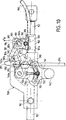
La fig. 10 est une vue, à grande échelle, correspondant au dispositif à mémoire de la fig. 8 en cours de déverrouillage.Fig. 10 is a view, on a large scale, corresponding to the memory device of FIG. 8 being unlocked.
La fig. 11 est une élévation latérale, à grande échelle, montrant le dispositif du vérin déverrouillé conforme à la fig. 9.Fig. 11 is a side elevation, on a large scale, showing the device of the unlocked jack according to FIG. 9.
A la fig. 2, on a représenté schématiquement la tige de vérin 101 qui est rectiligne et dont la section est rectangulaire ou carrée.In fig. 2, there is shown schematically the
Cette tige de vérin 101 porte, sur son extrémité 101a, un attelage de vérin 102 constitué par une tête percée d'un trou 103 destiné à la fixation de la tige de vérin 101 sur un organe solidaire, par exemple, du profilé mobile d'une glissière ou, dans le cas présent, sur un axe de rotation fixé sur une biellette solidaire de l'axe de rotation du dossier D tandis que l'assise S1 porte un boîtier 105 décrit en détail ci-après.This
130 désigne l'axe d'articulation du dossier D sur l'assise S du siège S1 (Fig. 1).130 designates the axis of articulation of the backrest D on the seat S of the seat S1 (Fig. 1).
Cette tige de vérin 101 repose sur des parties 104 du fond creux d'un boîtier interne 105 ayant en élévation une forme sensiblement polygonale, boîtier qui est recouvert par un boîtier couvercle 106 qui vient se fixer par des pattes recourbées 107 entrant dans des alvéoles 108 prévus à cet effet dans le boîtier couvercle 106.This
Il est prévu, des deux côtés du boîtier 105, 106, une pièce circulaire 109 (voir Fig. 3) dont le rôle est la fixation du boîtier 105, 106, soit à l'armature d'un siège, soit en un point d'un autre mécanisme de réglage en constituant ainsi le deuxième point de fixation du vérin à course rectiligne pour l'exemple de réalisation de la fig. 1.There is provided, on both sides of the
Ces pièces circulaires 109 sont placées dans l'axe médian vertical X-X du boîtier 105, 106. Les côtés inclinés 108a, 108b du boîtier 105 servent de chemins de guidage à deux grains 110, 111 en forme de chapeau de gendarme et dont la plus large base est usinée pour former à chaque fois deux rampes dentées 112, 113 séparées par un dégagement 114. Les rampes dentées 112, 113 sont destinées à coopérer avec des galets 115, 116 également striés montés sur des axes 117, 118 dépassant les faces latérales des galets 115, 116. Les axes 117, 118 sont montés dans une pièce 119 en forme de bicorne.These
Une came 120 est placée entre les deux grains 110, 111 et le mouvement de cette came est commandé par un arbre 121. L'ensemble, galets 115, 116, grains 110, 111, pièce en forme de bicorne 119, et came 120, est maintenu dans les boîtiers 105, 106. De plus, l'arbre 121 peut être commandé en rotation soit par un levier non représenté, soit par tout autre moyen de rotation désiré. Au moins un bossage 123 solidaire de l'arbre 121 est placé dans l'évidement central 119a de la pièce en forme de bicorne 119, la came 120 étant centrée au moyen d'alésages réalisés dans le boîtier 105, le couvercle 106 et l'arbre 121.A
De plus, un ressort spiral 223 (voir fig. 3) est fixé par l'une de ses extrémités sur l'arbre 121 et par son autre extrémité sur un plot solidaire du couvercle 106. On doit noter que 120b et 120c désignent les points de contact de la came 120 sur les faces latérales 110a, 111a des grains 110, 111.In addition, a spiral spring 223 (see fig. 3) is fixed by one of its ends to the
Finalement, la présence du ressort spiral 223 a pour effet de maintenir en position serrée les galets 115, 116 par l'intermédiaire des grains 110, 111 et de la came 120 sur la tige rectiligne 101 à section carrée ou rectangulaire.Finally, the presence of the
Comme on peut le voir à la fig. 2, un galet strié 301 est placé dans le fond creux 104a, 105a du boîtier 105 et est normalement au repos dans cette position.As can be seen in fig. 2, a
Ainsi, en faisant tourner l'arbre 121 dans le sens contraire aux aiguilles d'une montre, il est possible de provoquer une légère rotation de la came 120 dont les redents 120b, 120c libèrent ainsi la pression qu'exerce la came sur les grains 110, 111. Ainsi, les dentures 112, 113 des grains 110, 111 se dégagent des dentures des galets 115, 116 qui reposaient fermement sur la face supérieure de la tige du vérin 101 en bloquant celle-ci.Thus, by rotating the
Cette tige est donc libre et peut donc se déplacer dans les sens opposés désignés par la double flèche F1 (fig. 1).This rod is therefore free and can therefore move in the opposite directions designated by the double arrow F1 (fig. 1).
Dans certains cas et pour assurer, lorsque la came 120 est effacée, le soulèvement aisé des galets striés 115, 116, il est possible de prévoir, en supplément, deux ressorts courbes ayant sensiblement la forme d'un Ω et centrés autour des pièces circulaires 109 solidaires des deux côtés du boîtier 105 et du couvercle 106.In certain cases and to ensure, when the
Lorsqu'on a placé en position correcte la tige de vérin 101, il suffit de faire tourner l'arbre 121 dans le sens des aiguilles d'une montre pour que la came 120, par ses redents 120b et 120c, bloque de nouveau les grains 110, 111 qui s'abaissent en maintenant ainsi les galets 115, 116 sur la face supérieure de la tige de vérin 101.When the
Dans le cas où il se produirait un choc au moment où l'occupant du siège règle son dossier D (dans le cas de la fig. 1, mouvement suivant la flèche F2) ou la position de l'assise S soit d'avant en arrière, soit en élevant ou abaissant cette assise, le verrouillage de la tige 101 n'étant pas assuré, cette partie de siège considéré sous l'effet du freinage brutal se déplacerait à la vitesse initiale du véhicule occasionnant ainsi un accident grave mais, du fait du galet strié 301 qui se déplace également à la vitesse initiale du véhicule, ce galet monterait sur les rampes du creux 104a, 105a soit à sa droite, soit à sa gauche et entrerait en contact immédiatement avec le dessous de la tige 101 en provoquant un coincement de cette tige entre les parties inférieures du boîtier inférieur 105 et le galet strié 301 évitant ainsi un accident grave.In the event of a shock occurring when the seat occupant adjusts his backrest D (in the case of fig. 1, movement according to arrow F2) or the position of the seat S is from before rear, either by raising or lowering this seat, the locking of the
Le coincement se fait très rapidement car la rampe droite ou gauche du fond creux 104a étant d'une faible inclinaison inférieure à 30°, on obtient une commande instantanée brusque n'endommageant pas les pièces du vérin mécanique.The jamming takes place very quickly because the right or left ramp of the
Pour finir, il y a lieu d'indiquer que le galet 301 est traité dur pour permettre la pénétration de ses dents dans la tige 101 et la rampe considérée du boîtier 105.Finally, it should be noted that the
A la fig. 4, on a représenté un siège S1 comportant, à sa partie supérieure, une assise S et, à sa partie arrière, un dossier D, ce dernier étant articulé sur au moins un axe 250 solidaire de l'armature du siège S1 et permettant ainsi sa rotation aisée d'avant en arrière et d'arrière en avant suivant la flèche F2.In fig. 4, there is shown a seat S1 comprising, at its upper part, a seat S and, at its rear part, a backrest D, the latter being articulated on at least one
L'armature du siège S1 est montée sur au moins une sinon deux glissières 251 dont on voit le profilé inférieur 252 et le profilé supérieur 253. Bien entendu, une commande non représentée permet de verrouiller, à l'aide d'un peigne, le profilé supérieur coulissant 253 sur le profilé inférieur fixe 252 solidaire du plancher du véhicule.The frame of the seat S1 is mounted on at least one if not two
Les axes 250 d'articulation du dossier D sont solidaires des bras 254 qui permettent la commande d'avant en arrière et d'arrière en avant suivant la flèche F2 du dossier du siège.The
L'extrémité libre de chaque bras 254 porte un axe 255 qui est attelé à la tête 156 de la tige de vérin 157. Cette tige de vérin 157 pénètre dans le bottier 158 (voir fig. 5) constitué par deux coquilles, l'une extérieure 159 et l'autre intérieure 160, qui s'emboîtent l'une dans l'autre et qui sont prolongées vers leur partie avant 159a, 160a pour former guide de la tige 157 (Fig. 5). Le boîtier 158 est maintenu sur l'armature S1 du siège par des portées cylindriques 161.The free end of each
Comme cela a déjà été indiqué ci-dessus, l'intérieur du boîtier 158 contient deux grains 110, 111 en forme de chapeau de gendarme et dont la base est usinée pour former à chaque fois deux rampes dentées 112, 113 séparées par un dégagement 114. Les grains 110, 111 sont guidés par les parois latérales internes de la coquille intérieure 160. De plus, comme cela a déjà été indiqué, les grains 110, 111 peuvent être bloqués ou débloqués par une came 120 agissant sous l'action d'un arbre 121, l'arbre commandant la rotation d'au moins un bossage 123 qui tend à soulever la pièce en forme de bicorne 119 pour dégager les deux grains 110, 111 dont les rampes 112, 113 coopèrent avec des galets dentés 115, 116 montés sur des axes 117, 118 solidaires de la pièce 119 en forme générale de bicorne.As already indicated above, the interior of the
Il y a lieu également de remarquer que, sur l'arbre 121, sont montés, en plus de la came 120 et hors du boîtier 158, d'une part, un crochet 140 et, d'autre part, une pièce pendulaire 141 terminée à sa partie inférieure par une masselotte 142. La pièce 141 présente, dans sa partie intermédiaire, une zone évasée 143 percée d'une fenêtre 144.It should also be noted that, on the
Comme dans le cas de la fig. 2, la partie inférieure du boîtier 158 comporte sous la tige 157 une pièce 145 en V munie de deux dentures 145a, 145b dans lesquelles peut rouler un galet cranté 150 monté sur un axe 151 guidé dans des alvéoles 152, 153 parallèles aux rampes crantées 145a, 145b mais ces alvéoles sont creusées dans l'intérieur des coquilles extérieure 159 et intérieure 160.As in the case of fig. 2, the lower part of the
Lorsqu'il se produit un choc brutal, la masselotte 142 se déplace en 142a ou 142b suivant que le choc a lieu en avant ou en arrière et, à ce moment, le galet cranté 150 est poussé par son axe 151 soit vers l'avant, soit vers l'arrière en pénétrant ainsi sous la tige 157 du vérin qui se trouve être bloqué même dans le cas où, pour une raison quelconque, les galets 115, 116 ne seraient pas en position de blocage par exemple au moment d'un réglage de l'inclinaison du dossier D du siège S1.When a sudden impact occurs, the
Du fait que l'axe 151 du galet 150 est monté sur une tige pivotante 155 et est repoussé par un ressort 156 lorsque la masselotte 142 reprend sa place centrale, le galet 150 revient sous l'action conjuguée de la tige 155 et du ressort 156 dans la position médiane (représentée à la fig. 5) donc dans une position où la tige 157 n'est plus verrouillée par le galet 150.Because the
La fig. 6 montre la position de la masselotte 142 lorsqu'elle bloque le galet strié 150 sous la tige 157 en verrouillant ainsi solidement le dossier D du siège S1 alors que la tige 157 n'est plus en contact avec les galets striés 115, 116 puisque le levier C1, ayant agi sur le câble 190, a déplacé vers le haut la pièce en bicorne 119 (arbre 121, came 120 et crochet 140) provoquant le déverrouillage des galets striés 115, 116.Fig. 6 shows the position of the
La fig. 7 montre un siège équipé de l'organe de blocage de sécurité par inertie avec masselotte tel que décrit ci-dessus mais comportant en plus une mémoire de rappel en position verrouillée. En effet, comme on peut le voir aisément à la fig. 10, la tige 157 porte, derrière le boîtier 158, un boîtier 180 pouvant coulisser normalement sur la tige 157 et qui contient intérieurement une pièce 181 mobile verticalement à l'intérieur du boîtier 180 et présentant, à sa base, une découpe 182 en V qui est dentée avec un dégagement central 182a pour permettre la mise en place d'un galet strié 183 qui repose sur la partie supérieure de la tige 157. La pièce 181 peut coulisser verticalement dans le sens de la flèche F10 (fig. 10) sous l'action d'une came 185 montée sur un arbre 186 commandé par un levier 187 articulé sur l'arbre 186. La came 185 est placée à l'intérieur d'un espace alvéolaire 189 percé dans la pièce 181.Fig. 7 shows a seat fitted with the inertia safety blocking member with counterweight as described above but also comprising a memory for recalling in the locked position. Indeed, as can easily be seen in FIG. 10, the
L'extrémité inférieure 187a du levier 187 est attelée à un câble 190 qui est un câble du genre Bowden et que l'on voit très bien à la fig. 7. Ce câble Bowden est commandé par un levier 193 articulé à l'extrémité avant du siège S1.The
La partie supérieure terminale 187b du levier 187 se termine par une partie en redan 187c coopérant avec l'extrémité en creux 140a du levier 140.The upper
De plus, il est prévu, fixé sur un axe 280 du boîtier 158, un doigt pivotant 281 qui, normalement sous l'action d'un ressort non représenté enroulé autour de l'axe 280, ramène le doigt pivotant 281 dans la position en traits interrompus de la fig. 10.In addition, there is provided, fixed to an
Comme cela est visible en particulier à la fig. 7, une gaine Bowden 290 relie par un câble 292 le crochet 140 à un levier de manoeuvre 283 articulé sur le dossier D.As can be seen in particular in FIG. 7, a
Dans la position représentée à la fig. 10, le crochet 140 est maintenu en position abaissé (traits discontinus) du fait que le doigt 281 verrouille ce crochet à l'aide du cran 281a coopérant avec une butée ou un bossage rectiligne 140e prévu sur le crochet 140.In the position shown in fig. 10, the
Pour basculer le dossier vers l'avant (Fig. 9), la rotation du levier 283 suivant la flèche F9 entraîne le câble 292 guidé par la gaine 290 qui agit sur l'extrémité 187a du levier 187. Lors de l'abaissement du levier 187 suivant la flèche F11, l'extrémité 187c entre en contact avec la zone 140c. En fin de course du levier 187, le cran 281a du doigt 281 coopère avec le bossage rectiligne 140c et, de ce fait, maintient le crochet 140 dans la position de déverrouillage du vérin.To tilt the backrest forward (Fig. 9), the rotation of the
Ainsi, on libère le bottier 158 du boîtier 180 qui reste en place et l'on peut alors faire pivoter le dossier D (voir fig. 9) et faire avancer l'ensemble du siège S1 vers l'avant tout en gardant en mémoire la position normale de ce siège car alors il suffit de ramener ce dernier vers l'arrière pour qu'il reprenne la position représentée à la fig. 7.Thus, the
La fig. 11 représente la position du vérin 158 déplacé lorsque le dossier D occupe la position de la fig. 9. Dans ce cas, le boîtier 180 est resté en position mémorisée (fig. 9). Lors du retour du dossier D à la position de la fig. 7, l'extrémité 187c du levier 187 entre en contact avec la partie 281 du doigt de maintien du levier 140. Ce doigt 281 tourne alors dans le sens contraire aux aiguilles d'une montre pour libérer le levier 140 et permettre à la came 120 de reprendre sa position de verrouillage en poussant les galets 115, 116 sur la tige 157. On obtient ainsi le blocage du dossier D dans la position représentée à la fig. 7.Fig. 11 shows the position of the
Claims (6)
Applications Claiming Priority (2)
| Application Number | Priority Date | Filing Date | Title |
|---|---|---|---|
| FR929202701A FR2688274B1 (en) | 1992-03-06 | 1992-03-06 | DEVICE FOR LOCKING MECHANICAL CYLINDERS WITH A STRETCHED MOVEMENT, INCORPORATING AN INERTIA SECURITY LOCKING MEMBER. |
| FR9202701 | 1992-03-06 |
Publications (2)
| Publication Number | Publication Date |
|---|---|
| EP0559566A1 true EP0559566A1 (en) | 1993-09-08 |
| EP0559566B1 EP0559566B1 (en) | 1995-11-08 |
Family
ID=9427432
Family Applications (1)
| Application Number | Title | Priority Date | Filing Date |
|---|---|---|---|
| EP93400562A Expired - Lifetime EP0559566B1 (en) | 1992-03-06 | 1993-03-04 | Locking device for a rectilinear movement mechanical actuator, incorporating an inertia safety locking member |
Country Status (5)
| Country | Link |
|---|---|
| US (1) | US5301569A (en) |
| EP (1) | EP0559566B1 (en) |
| DE (1) | DE69300748T2 (en) |
| ES (1) | ES2079949T3 (en) |
| FR (1) | FR2688274B1 (en) |
Cited By (1)
| Publication number | Priority date | Publication date | Assignee | Title |
|---|---|---|---|---|
| WO2000055004A1 (en) * | 1999-03-17 | 2000-09-21 | Brose Fahrzeugteile Gmbh & Co. Kg, Coburg | Crash locking mechanism for an adjustment device of an automobile seat |
Families Citing this family (12)
| Publication number | Priority date | Publication date | Assignee | Title |
|---|---|---|---|---|
| FR2696795B1 (en) * | 1992-10-09 | 1994-12-16 | Faure Bertrand Automobile | Cylinder with deformable bar and rollers allowing the locking of two elements hinged together. |
| US5707112A (en) * | 1996-05-03 | 1998-01-13 | Magna Lomason Corporation | Linear recliner with memory seatback dump mechanism |
| US6009981A (en) * | 1996-09-17 | 2000-01-04 | Wolfe; William V. | Shaft locking or braking device for linear motion systems |
| DE19758582B4 (en) * | 1997-10-24 | 2006-02-23 | Stabilus Gmbh | Lock between relatively movable objects |
| US6761408B2 (en) | 2002-10-22 | 2004-07-13 | Intier Automotive Inc. | Linear recliner having an internal cam spring |
| US6910738B2 (en) | 2003-01-28 | 2005-06-28 | Fisher Dynamics Corporation | Device and method for assembling a recliner mechanism |
| US6890034B2 (en) | 2003-01-28 | 2005-05-10 | Fisher Dynamics Corporation | Compact recliner with locking cams |
| US20050168034A1 (en) * | 2004-01-21 | 2005-08-04 | Scott Fast | Disc recliner with dual cams |
| US7097253B2 (en) * | 2004-03-11 | 2006-08-29 | Fisher Dynamics Corporation | Round recliner assembly with rear folding latch |
| US7025422B2 (en) * | 2004-03-11 | 2006-04-11 | Fisher Dynamics Corporation | Round recliner assembly with rear folding latch |
| DE102006047398A1 (en) * | 2006-10-06 | 2008-05-21 | Lear Corporation, Southfield | 2-in-1-operating lever |
| US8579378B2 (en) * | 2010-12-01 | 2013-11-12 | Zodiac Seats France | Seat belt attachment for aircraft seat |
Citations (6)
| Publication number | Priority date | Publication date | Assignee | Title |
|---|---|---|---|---|
| DE3420103A1 (en) * | 1983-06-03 | 1984-12-06 | Gebr. Isringhausen, 4920 Lemgo | Rod clamping device for adjustable vehicle seats |
| FR2574721A1 (en) * | 1984-12-17 | 1986-06-20 | Tubauto | Continuous linear adjustment device for seats of land, sea or air vehicles |
| DE3508739A1 (en) * | 1985-03-12 | 1986-09-18 | Lennarz, Angela, 5138 Heinsberg | Rapid action coupling, especially for locking a distributor onto the pole of a large screen |
| EP0234160A1 (en) * | 1985-12-30 | 1987-09-02 | A. & M. COUSIN Etablissements COUSIN FRERES | Rectilinear jack which can be blocked by rollers in an indifferent position |
| US4865386A (en) * | 1988-06-01 | 1989-09-12 | General Motors Corporation | Cam action vehicle seat adjuster latch apparatus and method |
| FR2652129A1 (en) * | 1989-09-21 | 1991-03-22 | Cousin Freres Sa | DEVICE FOR LOCKING MECHANICAL CYLINDERS WITH EITHER RECTILINEAR OR CIRCULAR MOVEMENT. |
Family Cites Families (12)
| Publication number | Priority date | Publication date | Assignee | Title |
|---|---|---|---|---|
| US2750994A (en) * | 1952-05-27 | 1956-06-19 | Burns Aero Seat Co Inc | Chair back adjusting mechanism |
| FR1466417A (en) * | 1965-12-01 | 1967-01-20 | Publicite Francaise | Mechanical locking device and its applications, in particular to adjustable seats |
| FR1566264A (en) * | 1968-01-16 | 1969-05-09 | ||
| US3793903A (en) * | 1972-06-13 | 1974-02-26 | American Standard Prod Inc | Mechanism for seat adjustment |
| US3876248A (en) * | 1973-07-20 | 1975-04-08 | Rockwell International Corp | Extendible and contractible seat position adjustor |
| US3893730A (en) * | 1974-08-05 | 1975-07-08 | Lear Siegler Inc | Seat positioner |
| US4099777A (en) * | 1977-05-02 | 1978-07-11 | Lear Siegler, Inc. | Telescopic seat positioning mechanism |
| US4387926A (en) * | 1981-06-26 | 1983-06-14 | Rockwell International Corporation | Seat positioner |
| US4589301A (en) * | 1983-04-27 | 1986-05-20 | Hoover Universal, Inc. | Linearly infinitely variable mechanism |
| US4552405A (en) * | 1983-10-06 | 1985-11-12 | Rockwell International Corporation | Support for seat adjusting device |
| US4898424A (en) * | 1988-07-08 | 1990-02-06 | Fisher Dynamics Corporation | Linear seat recliner |
| US5052752A (en) * | 1990-06-21 | 1991-10-01 | Fisher Dynamics Corporation | Infinitely adjustable linear seat recliner |
-
1992
- 1992-03-06 FR FR929202701A patent/FR2688274B1/en not_active Expired - Fee Related
-
1993
- 1993-03-04 EP EP93400562A patent/EP0559566B1/en not_active Expired - Lifetime
- 1993-03-04 ES ES93400562T patent/ES2079949T3/en not_active Expired - Lifetime
- 1993-03-04 DE DE69300748T patent/DE69300748T2/en not_active Expired - Fee Related
- 1993-03-08 US US08/027,749 patent/US5301569A/en not_active Expired - Fee Related
Patent Citations (6)
| Publication number | Priority date | Publication date | Assignee | Title |
|---|---|---|---|---|
| DE3420103A1 (en) * | 1983-06-03 | 1984-12-06 | Gebr. Isringhausen, 4920 Lemgo | Rod clamping device for adjustable vehicle seats |
| FR2574721A1 (en) * | 1984-12-17 | 1986-06-20 | Tubauto | Continuous linear adjustment device for seats of land, sea or air vehicles |
| DE3508739A1 (en) * | 1985-03-12 | 1986-09-18 | Lennarz, Angela, 5138 Heinsberg | Rapid action coupling, especially for locking a distributor onto the pole of a large screen |
| EP0234160A1 (en) * | 1985-12-30 | 1987-09-02 | A. & M. COUSIN Etablissements COUSIN FRERES | Rectilinear jack which can be blocked by rollers in an indifferent position |
| US4865386A (en) * | 1988-06-01 | 1989-09-12 | General Motors Corporation | Cam action vehicle seat adjuster latch apparatus and method |
| FR2652129A1 (en) * | 1989-09-21 | 1991-03-22 | Cousin Freres Sa | DEVICE FOR LOCKING MECHANICAL CYLINDERS WITH EITHER RECTILINEAR OR CIRCULAR MOVEMENT. |
Cited By (2)
| Publication number | Priority date | Publication date | Assignee | Title |
|---|---|---|---|---|
| WO2000055004A1 (en) * | 1999-03-17 | 2000-09-21 | Brose Fahrzeugteile Gmbh & Co. Kg, Coburg | Crash locking mechanism for an adjustment device of an automobile seat |
| US6666508B1 (en) | 1999-03-17 | 2003-12-23 | Brose Fahrzeugteile Gmbh & Co. Kg, Coburg | Crash locking mechanism for an adjustment device of an automobile seat |
Also Published As
| Publication number | Publication date |
|---|---|
| FR2688274B1 (en) | 1994-06-10 |
| FR2688274A1 (en) | 1993-09-10 |
| ES2079949T3 (en) | 1996-01-16 |
| DE69300748D1 (en) | 1995-12-14 |
| US5301569A (en) | 1994-04-12 |
| EP0559566B1 (en) | 1995-11-08 |
| DE69300748T2 (en) | 1996-04-04 |
Similar Documents
| Publication | Publication Date | Title |
|---|---|---|
| EP0559566B1 (en) | Locking device for a rectilinear movement mechanical actuator, incorporating an inertia safety locking member | |
| EP0589759B1 (en) | Internal memory slide for positioning a seat | |
| EP1555171B1 (en) | Bonnet-lifter with a locking system by means of a hook | |
| WO2012013599A1 (en) | Handle of an opening element of a vehicle, comprising a grip part | |
| EP1778524A2 (en) | Safety device for use in the event of a vehicle roll over | |
| FR2795372A1 (en) | Hinge mechanism, for vehicle seat, has seat support and back support fitted together by co-axial circular elements, with acceleration sensitive device locking on to toothed outer edge of one of elements. | |
| EP0419336B1 (en) | Locking device for a mechanical actuator with rectilinear or circular movement | |
| EP3269643A1 (en) | Jump seat, and vehicle provided with said jump seat | |
| FR2922827A1 (en) | MOTOR VEHICLE SEAT FOLDING FORWARD INCLUDING JOINT LINING | |
| EP0234160B1 (en) | Rectilinear jack which can be blocked by rollers in an indifferent position | |
| EP0522939A1 (en) | Linear actuator, having one roller, for locking two interconnected elements | |
| EP0747256B1 (en) | Swiveling safety seat for a vehicle such as an airplane | |
| FR2716423A1 (en) | Safety device integrated into vehicle seats | |
| EP0457699A2 (en) | Device for automatically coupling a safety belt anchorage to a vehicle floor | |
| FR3116771A1 (en) | Vehicle seat with reclining seat and backrests to facilitate access to the rear seats | |
| EP3649015B1 (en) | Motor vehicle fitted with a load guard and comprising a seat backrest retention device | |
| FR2869340A1 (en) | Lateral casement opening device for motor vehicle, has blocking unit hindering, in case of lateral impact on casement, cooperation of handle and locking units if casement is unlocked, and actuated by deformation of outer skin due to impact | |
| FR2609948A1 (en) | INERTIAL LOCKING DEVICE FOR VEHICLE SEAT | |
| FR2848929A1 (en) | Automobile rear seat locking device comprises locking part on sheet metal support constituting mobile element and strike plate enclosed in plastic casing containing locking hook engaging strike plate | |
| EP1420980A1 (en) | Method for controlling a vehicle elevator side rails and device therefor | |
| FR2810933A1 (en) | Luggage retaining device for automobile comprises two rails fixed either side roof and frame mounted by runner sliding in rails | |
| EP0047703B1 (en) | Height adjustment device for vehicle seats | |
| FR2875191A1 (en) | Motor vehicle`s front/rear seat, has headrest actuating unit including activating unit that is subjected to thrust exerted from back of user in case of rear impact of vehicle in order to rotate headrest towards front | |
| FR2888554A1 (en) | Motor vehicle`s front door maintaining device, has pin automatically projected outside transversal housing for engaging in receptacle through inertia effect during frontal impact on motor vehicle | |
| FR2882706A1 (en) | VEHICLE SEAT HAVING A FOLDING BACKREST |
Legal Events
| Date | Code | Title | Description |
|---|---|---|---|
| PUAI | Public reference made under article 153(3) epc to a published international application that has entered the european phase |
Free format text: ORIGINAL CODE: 0009012 |
|
| 17P | Request for examination filed |
Effective date: 19930308 |
|
| AK | Designated contracting states |
Kind code of ref document: A1 Designated state(s): DE ES FR GB IT PT SE |
|
| 17Q | First examination report despatched |
Effective date: 19950104 |
|
| RTI1 | Title (correction) | ||
| GRAA | (expected) grant |
Free format text: ORIGINAL CODE: 0009210 |
|
| AK | Designated contracting states |
Kind code of ref document: B1 Designated state(s): DE ES FR GB IT PT SE |
|
| REF | Corresponds to: |
Ref document number: 69300748 Country of ref document: DE Date of ref document: 19951214 |
|
| GBT | Gb: translation of ep patent filed (gb section 77(6)(a)/1977) |
Effective date: 19951204 |
|
| REG | Reference to a national code |
Ref country code: ES Ref legal event code: FG2A Ref document number: 2079949 Country of ref document: ES Kind code of ref document: T3 |
|
| ITF | It: translation for a ep patent filed |
Owner name: STUDIO ING. ALFREDO RAIMONDI |
|
| PG25 | Lapsed in a contracting state [announced via postgrant information from national office to epo] |
Ref country code: SE Effective date: 19960208 |
|
| PLBE | No opposition filed within time limit |
Free format text: ORIGINAL CODE: 0009261 |
|
| STAA | Information on the status of an ep patent application or granted ep patent |
Free format text: STATUS: NO OPPOSITION FILED WITHIN TIME LIMIT |
|
| 26N | No opposition filed | ||
| PGFP | Annual fee paid to national office [announced via postgrant information from national office to epo] |
Ref country code: GB Payment date: 19970224 Year of fee payment: 5 |
|
| PGFP | Annual fee paid to national office [announced via postgrant information from national office to epo] |
Ref country code: ES Payment date: 19970321 Year of fee payment: 5 |
|
| PGFP | Annual fee paid to national office [announced via postgrant information from national office to epo] |
Ref country code: DE Payment date: 19980224 Year of fee payment: 6 |
|
| PG25 | Lapsed in a contracting state [announced via postgrant information from national office to epo] |
Ref country code: GB Free format text: LAPSE BECAUSE OF NON-PAYMENT OF DUE FEES Effective date: 19980304 |
|
| PG25 | Lapsed in a contracting state [announced via postgrant information from national office to epo] |
Ref country code: ES Free format text: LAPSE BECAUSE OF EXPIRATION OF PROTECTION Effective date: 19980305 |
|
| PGFP | Annual fee paid to national office [announced via postgrant information from national office to epo] |
Ref country code: FR Payment date: 19980330 Year of fee payment: 6 |
|
| GBPC | Gb: european patent ceased through non-payment of renewal fee |
Effective date: 19980304 |
|
| PG25 | Lapsed in a contracting state [announced via postgrant information from national office to epo] |
Ref country code: FR Free format text: LAPSE BECAUSE OF NON-PAYMENT OF DUE FEES Effective date: 19991130 |
|
| REG | Reference to a national code |
Ref country code: FR Ref legal event code: ST |
|
| PG25 | Lapsed in a contracting state [announced via postgrant information from national office to epo] |
Ref country code: DE Free format text: LAPSE BECAUSE OF NON-PAYMENT OF DUE FEES Effective date: 20000101 |
|
| REG | Reference to a national code |
Ref country code: ES Ref legal event code: FD2A Effective date: 20000201 |
|
| PG25 | Lapsed in a contracting state [announced via postgrant information from national office to epo] |
Ref country code: IT Free format text: LAPSE BECAUSE OF NON-PAYMENT OF DUE FEES;WARNING: LAPSES OF ITALIAN PATENTS WITH EFFECTIVE DATE BEFORE 2007 MAY HAVE OCCURRED AT ANY TIME BEFORE 2007. THE CORRECT EFFECTIVE DATE MAY BE DIFFERENT FROM THE ONE RECORDED. Effective date: 20050304 |
|
| PG25 | Lapsed in a contracting state [announced via postgrant information from national office to epo] |
Ref country code: PT Free format text: LAPSE BECAUSE OF NON-PAYMENT OF DUE FEES Effective date: 19960408 |