EP0559166B1 - Maschine zum Strecken von Häuten - Google Patents
Maschine zum Strecken von Häuten Download PDFInfo
- Publication number
- EP0559166B1 EP0559166B1 EP93103361A EP93103361A EP0559166B1 EP 0559166 B1 EP0559166 B1 EP 0559166B1 EP 93103361 A EP93103361 A EP 93103361A EP 93103361 A EP93103361 A EP 93103361A EP 0559166 B1 EP0559166 B1 EP 0559166B1
- Authority
- EP
- European Patent Office
- Prior art keywords
- stretching
- roller
- unit
- hide
- frame
- Prior art date
- Legal status (The legal status is an assumption and is not a legal conclusion. Google has not performed a legal analysis and makes no representation as to the accuracy of the status listed.)
- Expired - Lifetime
Links
- 238000003825 pressing Methods 0.000 claims description 20
- 230000009471 action Effects 0.000 claims description 10
- 238000006073 displacement reaction Methods 0.000 claims description 7
- 238000012549 training Methods 0.000 claims description 7
- 238000013519 translation Methods 0.000 claims description 7
- 230000000903 blocking effect Effects 0.000 claims description 2
- 238000000034 method Methods 0.000 description 16
- 230000008569 process Effects 0.000 description 7
- 238000001035 drying Methods 0.000 description 2
- 230000000694 effects Effects 0.000 description 2
- 230000006872 improvement Effects 0.000 description 2
- 239000010985 leather Substances 0.000 description 2
- 238000013459 approach Methods 0.000 description 1
- 230000008901 benefit Effects 0.000 description 1
- 230000002950 deficient Effects 0.000 description 1
- 238000010981 drying operation Methods 0.000 description 1
- 238000004519 manufacturing process Methods 0.000 description 1
- 238000012986 modification Methods 0.000 description 1
- 230000004048 modification Effects 0.000 description 1
- 238000011282 treatment Methods 0.000 description 1
- 238000009827 uniform distribution Methods 0.000 description 1
- 238000004804 winding Methods 0.000 description 1
Images
Classifications
-
- C—CHEMISTRY; METALLURGY
- C14—SKINS; HIDES; PELTS; LEATHER
- C14B—MECHANICAL TREATMENT OR PROCESSING OF SKINS, HIDES OR LEATHER IN GENERAL; PELT-SHEARING MACHINES; INTESTINE-SPLITTING MACHINES
- C14B1/00—Manufacture of leather; Machines or devices therefor
- C14B1/26—Leather tensioning or stretching frames; Stretching-machines; Setting-out boards; Pasting boards
Definitions
- the invention concerns a machine for the stretching hides.
- stretching machines which consist of at least a pair of rollers for the feed of the hide to be stretched, and of a stretching roller which is positioned in contact with the surface of the hide.
- the stretching roller presents on its external surface, a plurality of helicoidal blades which, beginning from the center of the roller, are wound following directions opposite to one another, therefore, when the stretching roller is made to rotate, its helicoidal blades cause a stretching following the orthogonal direction in relation to the feed direction itself, because of the contact of the helicoidal blades against the hide which is conveyed forward by the feeding rolls.
- the US-A-1 715 582 discloses a leather working machine for stretching leather fixed in a working table with hide clamping means and a carriage mounted above the table supporting a pressing and stretching roller which operates an half hide each operation.
- the FR-A-2 506 701 discloses a method for stretching and smooting hides realized by machine with more than one carriages presenting each one two stretching roller and one smooting roller. The rollers move from a starting point on the hide to one end of the hide, from this end of the hide to the opposite end of the hide, from the second end of the hide back to the starting point.
- Another inconvenience is that, if an optimum stretching cannot be guaranteed, a sometimes considerable percentage of the surface of the hide is wasted after the drying operation.
- the present invention is disclosed. Its main purpose is that of obtaining a stretching machine to perform a method for stretching the hides, through which, in relation to methods and machines belonging to the known technique, it is possible to obtain an improved stretching of the hide and, as a consequence an improved quality of the same after the drying process. Another purpose is to obtain a better use of the total surface of the hide.
- the mentioned purposes are reached by the stretching machine of the invention, the main features of which are in accordance with claim 1.
- the machine according to the invention allows an improvement of the stretching process and, as a consequence an overall improvement of the hide quality after the same has been dried.
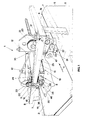
- the stretching machine accorto the invention As can be observed in Fig. 1, the stretching machine accorto the invention, indicated as whole with 1, consists of a conveyor belt 2 on which the hide 14 to be stretched is laid flat and which, through the advancing of the conveyor belt 2 following direction 4, is brought into the position where it will be stretched over a working bench 5 which is attached to the support base 6 of the stretching machine.
- a frame 13 is attached to the support 6 of the machine by means of uprights 7, said frame overhanging the working bench 5 and supporting a pressing unit, indicated as a whole with 10, which is arranged at an essentially central position in relation to the working bench 5.
- Said frame also supports a pair of stretching rollers, 8 and 9 respectively, which are parallel to the working bench 5 and arranged at opposite positions in relation to the pressing unit 10.
- the pressing unit indicated as whole with 10 consists in turn, of a pressure roller 11 which can be displaced vertically in relation to the working bench 5 through a pair of pneumatic cylinders 12 arranged at the ends of said roller and attached to frame 13, through which, the pressing roller 11 blocks the hide 14 ready to be processed, against the surface of the working bench 5.
- the stretching roller 8 is supported at each of its ends , by a training plate 16 fulcred through a pivot 18 on a support plate 20 which assures on frame 13 through a gear wheel 22, visible in Fig. 1, which in turn engages a rack (not visible in Fig. 1) applied on frame 13.
- the stretching roller 9 is supported at each of its ends by a training plate 17 fulcred through a pivot 19 on a support plate 21 which assures on the same frame 13 through another gear wheel 23 engaging the same rack which is engaged by the previously mentioned gear wheel 22.
- each stretching roller is in turn each in contact at one point, 44 and 45 respectively, with the ends 42 and 43 respectively of the stem of a pneumatic cylinders connected with the corresponding support plate 20 and 21, so that, when said cylinders are made to function by means of compressed air, each stretching roller can be displaced vertically in relation to the working bench 5, according to one of the two directions of arrows 40 and 41.
- the support plates 20 and 21 of the stretching roller 8 and of the stretching roller 9 respectively, are joined together in correspondence with both ends of the rollers through a connecting rod 24, so that as a result, the rollers 8 and 9 are firmly connected with each other.
- one of the support plates 20, is connected through a bracket 3, to the end of stem 26 of a pneumatic cylinder 25 attached to the frame 13 which, whenever it is supplied with compressed air, moves both the support plates 20 and 21 which are joined together, and, as a consequence, it also causes the rollers 8 and 9, which are supported by said plates, to move following the directions indicated by the arrows 27 or 28, along frame 13, subject to the movement of stem 26.
- both stretching rollers 8 and 9 are bound to frame 13 by means of a translation kinematic unit, indicated as a whole with 70, along frame 13 itself, and comprising a pneumatic cylinder 25, whose stem 26 is mechanically connected to the support plates 20 and 21, each of them being equipped with a gear wheel, 22 and 23 respectively, engaging the rack attached to the frame 13.
- a translation kinematic unit indicated as a whole with 70, along frame 13 itself, and comprising a pneumatic cylinder 25, whose stem 26 is mechanically connected to the support plates 20 and 21, each of them being equipped with a gear wheel, 22 and 23 respectively, engaging the rack attached to the frame 13.
- the stretching roller 8 is connected with the support plate 20 through a vertical displacement unit, indicated as a whole with 72, and comprising a pneumatic cylinder 42 attached to the support plate 20 and whose stem is in contact with the training plate 16 at its point 44.
- the stretching roller 9 is connected with the support plate 21 through another vertical displacement unit, indicated as a whole with 71, and comprising a pneumatic cylinder 43 attached to the support plate 21 and whose stem is in contact with the training plate 17 at its point 45.
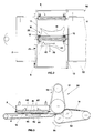
- Each stretching roller 8 and 9 is also equipped with a kinematic rotation unit operated by an electric motor (not represented in the Fig.) which causes each roller to rotate around its horizontal axis, 46 and 47 respectively.
- an electric motor not represented in the Fig.
- the stretching roller 8 is made to rotate around its axis 46 by a kinematic unit, indicated as a whole with 30, which consists of a pulley 32 keyed to the axis 46 of the roller itself, said pulley receiving through a driving belt 34, the motion of a driving pulley 36 keyed on the shaft of the driving motor.
- the stretching roller 9 (not visible in Fig.
- the kinematic unit 31 which comprises a pulley 33 keyed to the axis 47 of the roller itself, said pulley being made to rotate by a driving pulley 37 keyed on the axis of the driving motor through the action of a belt 35.
- each stretching roller 8 and 9 can be displaced vertically so as to approach or move away from the working bench 5, and it can also rotate around its axis and simultaneously it can be translated along frame 13.
- a removal unit for the hide indicated as a whole with 50, which consists of a top motor-driven conveyor belt 51 adhering to a bottom motor-driven conveyor belt 52, both belts being made to move following respectively directions 55 and 56, and allowing the removal of the hide 14 from the machine after the stretching process has been completed.
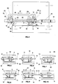
- the working process starts when both the pressing roller 11 and the stretching rollers 8 and 9 are in the position represented in Fig. 5, that is to say, lifted away from the hide 14 so that, by operating the pneumatic cylinder 12, belonging to the pressing unit 10, the pressing roller 11 is forced against the hide 14, thus blocking the latter on the working bench 5, as can be observed in Fig. 6. Simultaneously, the stretching roller 9 is lowered too, by operating the pneumatic cylinder 43 belonging to the vertical displacement unit 71, while the stretching roller 8 remains in the lifted position.
- portion 60 of the hide 14 begins the stretching process of portion 60 of the hide 14, such stretching occurring because of the action of the protruding helicoidal blades 41 applied on each stretching roller and visible in Fig. 3.
- the stretching of the hide occurs only in the opposite directions of winding of the stretching rollers.
- the stretching roller 9 As will be observed in Fig. 7, has reached its end stroke toward direction 28, and, therefore, it has completed the stretching of area 60 of the hide 14 being processed, the stretching roller 9 is lifted up by means of a pneumatic piston 43, as will be observed in Fig. 8, while the stretching roller 8 is simultaneously lowered and is in turn made to rotate around its axis through the kinematic unit 30 and simultaneously it is also displaced following the direction of arrow 27 by the action of the kinematic translation unit 70. The roller 8 therefore, starts moving following direction 27, thus causing the stretching of the part 61 of the hide 14, visible in the schematic representation of Fig. 9.
- the stretching operation is completed when the stretching roller 8 reaches the end of its stroke and, in such a position, it is lifted up again through the action of the pneumatic cylinder 42. Simultaneously the pressing roller 11 is lifted up, too, thus achieving the configuration represented in Fig. 10, wherein the hide 14, which has been stretched, can be removed from the stretching machine.
- the conveyor belt 2 is made to roll again in direction 4, as can be observed in Fig. 3, so that the belts 51 and 52 of the removal unit 50 catch the hide 14 which will then be removed from the machine.
- helicoidal blades 41 wound on the surface of each roller and, beginning from the center, following opposed axial directions, they can be replaced with variously shaped rough-surfaced ribs, applied on the surface of the roller or with elements having different shape and dimensions however arranged with opposed and essentially helicoidal directions along the axial direction of the roller.
- Said surfaces or contact elements can be arranged according to one or more principles and they may acquire any configuration and any shape.
- the driving means of both the pressing roller 11 and the stretching rollers 8 and 9 can be of any type, such as electrical, pneumatic, hydraulic, mechanical or others.
- stretching rollers these can be modified, too.
- a different embodiment could foresee a single stretching roller placed at one side only in relation to the pressing unit, wherein said stretching roller always moves in the same direction in relation to the pressing unit, while the hide to be processed is placed on a rotating working bench.
- the stretching roller performs the stretching of the hide with a back and forth movement following the same direction, wherein in the first movement it stretches half of the hide, while the other half, after the hide has been rotated by 180 degrees, is stretched during the backward movement.
- Another different embodiment can foresee the two stretching rollers to be independent of each other, each of them possibly performing the translation movement simultaneously with the other, each being driven by its own driving means.
Landscapes
- Engineering & Computer Science (AREA)
- Manufacturing & Machinery (AREA)
- Mechanical Engineering (AREA)
- Chemical & Material Sciences (AREA)
- Organic Chemistry (AREA)
- Treatment Of Fiber Materials (AREA)
- Treatment And Processing Of Natural Fur Or Leather (AREA)
- Shaping By String And By Release Of Stress In Plastics And The Like (AREA)
Claims (9)
- Erweiterungsmaschine (1), die einen über der Werkbank (5) angeordneten Rahmen (3) einschliesst und folgende Bestandteile trägt:- ein Drückaggregat (10), das in einer im wesentlichen mittigen Lage im Verhältnis zur Werkbank (5) angeordnet ist und mit mindestens einem Drückelement (11) zum Festhalten des Fells (14) an der Werkbank (5) ausgerüstet ist;- Erweiterungswalzen, die mit Erweiterungselementen ausgerüstet und mit einem ersten kinematischen Aggregat (30, 31) mechanisch verbunden sind, das sie um ihre eigene Achse zum Drehen treibt, und mit einem zweiten kinematischen Aggregat (70) zur Versetzung entlang des Rahmens (13) ausgerüstet sind, dadurch gekennzeichnet, daß die Erweiterungswirkung von einem Paar Erweiterungswalzen (8, 9) ausgeübt wird, die parallel zur Werkbank und an gegenüberliegenden Stellungen in Verhältnis zum Drückaggregat (10) angeornet sind, wobei jede Walze (8, 9) mit einem Aggregat (72, 71) zur eigenen senkrechten Verstellung im Verhältnis zur Werkbank (5) ausgerüstet ist, indem das genannte Aggregat (72, 71) die Walze (8, 9) von dem Fell (14) entfernt hält, als die andere Walze (9, 8) am Fell haftet, um ihre eigene Achse dreht und, gleichzeitig, sich entlang des Rahmens (13) der genannten Maschine versetzt.
- Erweiterungsmaschine nach Anspruch 1., dadurch gekennzeichnet, daß die Werkbank (5) ein Zufuhr-Förderband (2) einschliesst, worauf das zu erweiternde Fell (14) aufgelegt wird, und das auf der Oberfläche der Werkbank (5) gleitet, wobei das Ende des genannten Förderbands (2) ein Ablade-Aggregat (50) zum Abladen der erweiteten Felle speist.
- Erweiterungsmaschine nach Anspruch 1., dadurch gekennzeichnet, daß das kinematische Aggregat (70) zur Versetzung der Erweiterungswalzen (8, 9) entlang des Rahmens (13), einen pneumatischen Zylinder (25) einschliesst, der am Rahmen (13) befestigt ist und dessen Schaft (26) an mindestens einer Stützplatte (20, 21) befestigt ist, wobei die genannten Stützplatten fest miteinander verbunden sind, und jede Stützplatte ein Ende jeder der genannten Erweiterungswalzen stützt, wobei jede der genannten Stützplatten mit einem Zahnrad (22, 23) versehen ist, das daran leer gekeilt ist und einer am Rahmen (13) befestigten Zahnstange angepasst ist.
- Erweiterungsmaschine nach Anspruch 3., dadurch gekennzeichnet, daß das Aggregat (72, 71) zur senkrechten Versetzung jeder Walze (8, 9) eine Zugplatte (16,17) einschliesst, die die Stützwalze an ihrem Ende stützt und an ihrer entsprechenden Stützplatte (20, 21), die zum Verstellungsaggregat (70) gehört, mittels eines Zapfens (18, 19) leer gekeilt ist, worum sie leerlaufen kann, als die Wirkung eines an der entsprechenden Stützplatte (20, 21) befestigten pneumatischen Zylinders (42, 43), dessen Kolbstange an einer Stelle (44, 45) mit seiner entsprechenden Zugplatte (16, 17) in Berührung ist, sie zum Drehen treibt.
- Erweiterungsmaschine nach Anspruch 1., dadurch gekennzeichnet, daß das kinematische Aggregat (30, 31) zur Umdrehung jeder Erweiterungswalze (8, 9) eine Keilriemenscheibe (32, 33) aufweist, die an der Achse (46, 47) der Walze gekeilt ist, die durch einen Keilriemen (34, 35) die Bewegung aus einer an einem Antriebsmotor gekeilten Keilriemenscheibe (36, 37) nimmt.
- Erweiterungsmaschine nach Anspruch 1., dadurch gekennzeichnet, daß das Druckelement des Drücksaggregats (10) eine Drückwalze ist (11), die sich im Verhältnis zur Werkbank (5) durch mindestens einen am Rahmen (13) befestigten pneumatischen Antriebszylinder (12) senkrecht bewegt.
- Erweiterungsmaschine nach Anspruch 1., dadurch gekennzeichnet, daß die Erweiterungselemente jeder Erweiterungswalze (8, 9) eine Mehrzahl von schraubenförmigen Messern (41) sind, die um ihre äussere Oberfläche in gegenüberliegenden Richtungen - von der Mitte (43) jeder Walze anfangend - angeordnet sind.
- Erweiterungsmaschine nach Anspruch 2., dadurch gekennzeichnet, daß das Aggregat (50) zum Abladen des Fells (14), nachdem das Erweiterungsverfahren ausgeführt worden ist, ein Paar von motorangetriebener Förderbänder (55, 56) aufweist, die aneinander anhaften und mit dem Zufuhr-Förderband (2) gefluchtet sind, da wo dieses die Stellung erreicht, wo das Fell abgeladen wird, nachdem das Erweiterungsverfahren ausgeführt worden ist.
- Erweiterungsmaschine nach Anspruch 3., dadurch gekennzeichnet, daß die Stützplatten (20, 21), die einzeln das Ende einer Erweiterungswalze stützen und an der gleichen Seite angeordnet sind, fest mit einander durch einen Verbindungsstab (24) verbunden sind.
Applications Claiming Priority (2)
| Application Number | Priority Date | Filing Date | Title |
|---|---|---|---|
| ITVI920031A IT1258110B (it) | 1992-03-05 | 1992-03-05 | Metodo per l'allargatura delle pelli e macchina allargatrice atta a realizzare tale metodo |
| ITVI920031 | 1992-03-05 |
Publications (2)
| Publication Number | Publication Date |
|---|---|
| EP0559166A1 EP0559166A1 (de) | 1993-09-08 |
| EP0559166B1 true EP0559166B1 (de) | 1997-07-30 |
Family
ID=11424845
Family Applications (1)
| Application Number | Title | Priority Date | Filing Date |
|---|---|---|---|
| EP93103361A Expired - Lifetime EP0559166B1 (de) | 1992-03-05 | 1993-03-03 | Maschine zum Strecken von Häuten |
Country Status (4)
| Country | Link |
|---|---|
| EP (1) | EP0559166B1 (de) |
| DE (1) | DE69312529T2 (de) |
| ES (1) | ES2107567T3 (de) |
| IT (1) | IT1258110B (de) |
Families Citing this family (4)
| Publication number | Priority date | Publication date | Assignee | Title |
|---|---|---|---|---|
| IT1393001B1 (it) * | 2009-02-19 | 2012-04-02 | Bauce Tri Ma S R L | Metodo per l'allargatura di pelli e macchina allargatrice atta a realizzare tale metodo |
| IT1404081B1 (it) * | 2011-01-13 | 2013-11-08 | Dal Lago S R L | Installazione di pressatura per l'asciugatura di pelli animali. |
| ITVE20110018A1 (it) * | 2011-03-28 | 2012-09-29 | Dal Lago S R L | Macchina stenditrice di pelli animali |
| CN106435049A (zh) * | 2016-10-24 | 2017-02-22 | 南通思瑞机器制造有限公司 | 一种真空干燥机展皮机构 |
Family Cites Families (3)
| Publication number | Priority date | Publication date | Assignee | Title |
|---|---|---|---|---|
| DE242875C (de) * | ||||
| US1715582A (en) * | 1927-05-14 | 1929-06-04 | Machinery Dev Company | Leather-working machine |
| FR2506781A1 (fr) * | 1981-05-26 | 1982-12-03 | Cabrol Pierre | Procede et machine pour le travail des cuirs et peaux, utilisant des cylindres rotatifs d'etirage et de lissage |
-
1992
- 1992-03-05 IT ITVI920031A patent/IT1258110B/it active IP Right Grant
-
1993
- 1993-03-03 EP EP93103361A patent/EP0559166B1/de not_active Expired - Lifetime
- 1993-03-03 DE DE69312529T patent/DE69312529T2/de not_active Expired - Fee Related
- 1993-03-03 ES ES93103361T patent/ES2107567T3/es not_active Expired - Lifetime
Also Published As
| Publication number | Publication date |
|---|---|
| ITVI920031A1 (it) | 1993-09-05 |
| EP0559166A1 (de) | 1993-09-08 |
| ES2107567T3 (es) | 1997-12-01 |
| DE69312529T2 (de) | 1998-03-05 |
| ITVI920031A0 (it) | 1992-03-05 |
| IT1258110B (it) | 1996-02-20 |
| DE69312529D1 (de) | 1997-09-04 |
Similar Documents
| Publication | Publication Date | Title |
|---|---|---|
| FI84083B (fi) | Foerfarande och anordning foer att avlaegsna fettet och koettet fraon koettsidan av skinnet eller paelsen fraon ett paelsdjur. | |
| EP0559166B1 (de) | Maschine zum Strecken von Häuten | |
| US2197906A (en) | Method and machine for forming metal | |
| GB2073270A (en) | Apparatus for ironing fabrics, in particular knitted fabrics | |
| CN110371742B (zh) | 一种棉布加工用修边设备 | |
| EP1075552B1 (de) | Vorrichtung zur kontinuierlichen automatischen Verarbeitung und Färbung der Ränder und Spitzen von Gürteln oder anderen Bändern aus Leder oder Kunststoff | |
| EP0417685A2 (de) | Maschine zum Abschaben von Fellen mit einzigem Durchlauf des Fells | |
| CN222944240U (zh) | 一种冷弯成型机弯折角度调整装置 | |
| CN221166578U (zh) | 一种通过式挤水机 | |
| US4542634A (en) | Staking machine | |
| CN111616229A (zh) | 豆筋生产装置 | |
| CN212101203U (zh) | 一种竹篾自动上料装置 | |
| CN212771498U (zh) | 一种纺织面料加工熨烫装置 | |
| KR100412260B1 (ko) | 금속판재의 헤어라인 가공기 | |
| CN212049815U (zh) | 一种纺布用裁切分卷设备 | |
| CN222770344U (zh) | 一种安全性高的坯布传送分切设备 | |
| US3745714A (en) | Tipping device for work holder | |
| US1874273A (en) | Fur treating apparatus | |
| CN221186787U (zh) | 一种纸筒截断机构 | |
| CN222226849U (zh) | 一种pvc布加工用高频压花机 | |
| US4392596A (en) | Hosiery trimming apparatus | |
| CN223445826U (zh) | 面料压花装置 | |
| CN223671984U (zh) | 一种网编织袋边缘处理设备 | |
| CN218948730U (zh) | 一种油墨印刷快速干燥装置 | |
| CN112167775A (zh) | 一种皮鞋生产加工用的皮鞋面料裁剪设备及其使用方法 |
Legal Events
| Date | Code | Title | Description |
|---|---|---|---|
| PUAI | Public reference made under article 153(3) epc to a published international application that has entered the european phase |
Free format text: ORIGINAL CODE: 0009012 |
|
| AK | Designated contracting states |
Kind code of ref document: A1 Designated state(s): DE ES FR GB IT PT |
|
| 17P | Request for examination filed |
Effective date: 19931104 |
|
| 17Q | First examination report despatched |
Effective date: 19951228 |
|
| GRAG | Despatch of communication of intention to grant |
Free format text: ORIGINAL CODE: EPIDOS AGRA |
|
| RAP3 | Party data changed (applicant data changed or rights of an application transferred) |
Owner name: BAGGIO TECNOLOGIE SRL |
|
| GRAH | Despatch of communication of intention to grant a patent |
Free format text: ORIGINAL CODE: EPIDOS IGRA |
|
| GRAH | Despatch of communication of intention to grant a patent |
Free format text: ORIGINAL CODE: EPIDOS IGRA |
|
| GRAA | (expected) grant |
Free format text: ORIGINAL CODE: 0009210 |
|
| AK | Designated contracting states |
Kind code of ref document: B1 Designated state(s): DE ES FR GB IT PT |
|
| REF | Corresponds to: |
Ref document number: 69312529 Country of ref document: DE Date of ref document: 19970904 |
|
| ITF | It: translation for a ep patent filed | ||
| PG25 | Lapsed in a contracting state [announced via postgrant information from national office to epo] |
Ref country code: PT Effective date: 19971105 |
|
| ET | Fr: translation filed | ||
| REG | Reference to a national code |
Ref country code: ES Ref legal event code: FG2A Ref document number: 2107567 Country of ref document: ES Kind code of ref document: T3 |
|
| PGFP | Annual fee paid to national office [announced via postgrant information from national office to epo] |
Ref country code: FR Payment date: 19980224 Year of fee payment: 6 |
|
| PGFP | Annual fee paid to national office [announced via postgrant information from national office to epo] |
Ref country code: DE Payment date: 19980526 Year of fee payment: 6 |
|
| PLBE | No opposition filed within time limit |
Free format text: ORIGINAL CODE: 0009261 |
|
| STAA | Information on the status of an ep patent application or granted ep patent |
Free format text: STATUS: NO OPPOSITION FILED WITHIN TIME LIMIT |
|
| 26N | No opposition filed | ||
| PG25 | Lapsed in a contracting state [announced via postgrant information from national office to epo] |
Ref country code: FR Free format text: LAPSE BECAUSE OF NON-PAYMENT OF DUE FEES Effective date: 19991130 |
|
| REG | Reference to a national code |
Ref country code: FR Ref legal event code: ST |
|
| PG25 | Lapsed in a contracting state [announced via postgrant information from national office to epo] |
Ref country code: DE Free format text: LAPSE BECAUSE OF NON-PAYMENT OF DUE FEES Effective date: 20000101 |
|
| PGFP | Annual fee paid to national office [announced via postgrant information from national office to epo] |
Ref country code: GB Payment date: 20000228 Year of fee payment: 8 |
|
| PGFP | Annual fee paid to national office [announced via postgrant information from national office to epo] |
Ref country code: ES Payment date: 20000310 Year of fee payment: 8 |
|
| PG25 | Lapsed in a contracting state [announced via postgrant information from national office to epo] |
Ref country code: GB Free format text: LAPSE BECAUSE OF NON-PAYMENT OF DUE FEES Effective date: 20010303 |
|
| PG25 | Lapsed in a contracting state [announced via postgrant information from national office to epo] |
Ref country code: ES Free format text: LAPSE BECAUSE OF NON-PAYMENT OF DUE FEES Effective date: 20010305 |
|
| GBPC | Gb: european patent ceased through non-payment of renewal fee |
Effective date: 20010303 |
|
| REG | Reference to a national code |
Ref country code: ES Ref legal event code: FD2A Effective date: 20030303 |
|
| PG25 | Lapsed in a contracting state [announced via postgrant information from national office to epo] |
Ref country code: IT Free format text: LAPSE BECAUSE OF NON-PAYMENT OF DUE FEES Effective date: 20080303 |
|
| PGFP | Annual fee paid to national office [announced via postgrant information from national office to epo] |
Ref country code: IT Payment date: 20090319 Year of fee payment: 17 |
|
| PGRI | Patent reinstated in contracting state [announced from national office to epo] |
Ref country code: IT Effective date: 20110616 |
|
| PGRI | Patent reinstated in contracting state [announced from national office to epo] |
Ref country code: IT Effective date: 20110616 |