EP0558898B1 - Thermal evaporation in two planes - Google Patents
Thermal evaporation in two planes Download PDFInfo
- Publication number
- EP0558898B1 EP0558898B1 EP93100690A EP93100690A EP0558898B1 EP 0558898 B1 EP0558898 B1 EP 0558898B1 EP 93100690 A EP93100690 A EP 93100690A EP 93100690 A EP93100690 A EP 93100690A EP 0558898 B1 EP0558898 B1 EP 0558898B1
- Authority
- EP
- European Patent Office
- Prior art keywords
- horizontal
- metal
- vertical
- vacuum
- metallizing
- Prior art date
- Legal status (The legal status is an assumption and is not a legal conclusion. Google has not performed a legal analysis and makes no representation as to the accuracy of the status listed.)
- Expired - Lifetime
Links
- 238000002207 thermal evaporation Methods 0.000 title description 5
- 229910052751 metal Inorganic materials 0.000 claims description 33
- 239000002184 metal Substances 0.000 claims description 33
- 238000001704 evaporation Methods 0.000 claims description 28
- 230000008020 evaporation Effects 0.000 claims description 20
- 238000000034 method Methods 0.000 claims description 13
- 229910052738 indium Inorganic materials 0.000 description 15
- APFVFJFRJDLVQX-UHFFFAOYSA-N indium atom Chemical compound [In] APFVFJFRJDLVQX-UHFFFAOYSA-N 0.000 description 15
- 239000000758 substrate Substances 0.000 description 12
- 239000002923 metal particle Substances 0.000 description 8
- 239000004033 plastic Substances 0.000 description 6
- 229920003023 plastic Polymers 0.000 description 6
- 238000005260 corrosion Methods 0.000 description 4
- 230000007797 corrosion Effects 0.000 description 4
- 239000000463 material Substances 0.000 description 4
- JOYRKODLDBILNP-UHFFFAOYSA-N Ethyl urethane Chemical compound CCOC(N)=O JOYRKODLDBILNP-UHFFFAOYSA-N 0.000 description 3
- 239000011248 coating agent Substances 0.000 description 3
- 238000000576 coating method Methods 0.000 description 3
- WFKWXMTUELFFGS-UHFFFAOYSA-N tungsten Chemical compound [W] WFKWXMTUELFFGS-UHFFFAOYSA-N 0.000 description 3
- 229910052721 tungsten Inorganic materials 0.000 description 3
- 239000010937 tungsten Substances 0.000 description 3
- 238000001771 vacuum deposition Methods 0.000 description 3
- IJGRMHOSHXDMSA-UHFFFAOYSA-N Atomic nitrogen Chemical compound N#N IJGRMHOSHXDMSA-UHFFFAOYSA-N 0.000 description 2
- 229910045601 alloy Inorganic materials 0.000 description 2
- 239000000956 alloy Substances 0.000 description 2
- 230000015572 biosynthetic process Effects 0.000 description 2
- 238000004581 coalescence Methods 0.000 description 2
- 238000000151 deposition Methods 0.000 description 2
- 230000008021 deposition Effects 0.000 description 2
- 239000007788 liquid Substances 0.000 description 2
- 239000007769 metal material Substances 0.000 description 2
- 230000004048 modification Effects 0.000 description 2
- 238000012986 modification Methods 0.000 description 2
- 239000002991 molded plastic Substances 0.000 description 2
- NIXOWILDQLNWCW-UHFFFAOYSA-N acrylic acid group Chemical group C(C=C)(=O)O NIXOWILDQLNWCW-UHFFFAOYSA-N 0.000 description 1
- 210000003298 dental enamel Anatomy 0.000 description 1
- 230000001419 dependent effect Effects 0.000 description 1
- 238000009792 diffusion process Methods 0.000 description 1
- 229920001971 elastomer Polymers 0.000 description 1
- 239000000806 elastomer Substances 0.000 description 1
- 239000011521 glass Substances 0.000 description 1
- 238000010438 heat treatment Methods 0.000 description 1
- 238000002347 injection Methods 0.000 description 1
- 239000007924 injection Substances 0.000 description 1
- 238000001746 injection moulding Methods 0.000 description 1
- 239000011810 insulating material Substances 0.000 description 1
- 239000004816 latex Substances 0.000 description 1
- 229920000126 latex Polymers 0.000 description 1
- 238000004519 manufacturing process Methods 0.000 description 1
- 229910052757 nitrogen Inorganic materials 0.000 description 1
- 230000006911 nucleation Effects 0.000 description 1
- 238000010899 nucleation Methods 0.000 description 1
- 238000010943 off-gassing Methods 0.000 description 1
- 239000002245 particle Substances 0.000 description 1
- 239000012071 phase Substances 0.000 description 1
- 229920002635 polyurethane Polymers 0.000 description 1
- 239000004814 polyurethane Substances 0.000 description 1
- 238000005086 pumping Methods 0.000 description 1
- 239000011347 resin Substances 0.000 description 1
- 229920005989 resin Polymers 0.000 description 1
- 229920002545 silicone oil Polymers 0.000 description 1
- 239000000243 solution Substances 0.000 description 1
- 239000002904 solvent Substances 0.000 description 1
- 239000000126 substance Substances 0.000 description 1
- 239000012808 vapor phase Substances 0.000 description 1
- 238000009834 vaporization Methods 0.000 description 1
- 230000008016 vaporization Effects 0.000 description 1
- XLYOFNOQVPJJNP-UHFFFAOYSA-N water Chemical compound O XLYOFNOQVPJJNP-UHFFFAOYSA-N 0.000 description 1
- 239000002023 wood Substances 0.000 description 1
Images

Classifications
-
- C—CHEMISTRY; METALLURGY
- C23—COATING METALLIC MATERIAL; COATING MATERIAL WITH METALLIC MATERIAL; CHEMICAL SURFACE TREATMENT; DIFFUSION TREATMENT OF METALLIC MATERIAL; COATING BY VACUUM EVAPORATION, BY SPUTTERING, BY ION IMPLANTATION OR BY CHEMICAL VAPOUR DEPOSITION, IN GENERAL; INHIBITING CORROSION OF METALLIC MATERIAL OR INCRUSTATION IN GENERAL
- C23C—COATING METALLIC MATERIAL; COATING MATERIAL WITH METALLIC MATERIAL; SURFACE TREATMENT OF METALLIC MATERIAL BY DIFFUSION INTO THE SURFACE, BY CHEMICAL CONVERSION OR SUBSTITUTION; COATING BY VACUUM EVAPORATION, BY SPUTTERING, BY ION IMPLANTATION OR BY CHEMICAL VAPOUR DEPOSITION, IN GENERAL
- C23C16/00—Chemical coating by decomposition of gaseous compounds, without leaving reaction products of surface material in the coating, i.e. chemical vapour deposition [CVD] processes
- C23C16/44—Chemical coating by decomposition of gaseous compounds, without leaving reaction products of surface material in the coating, i.e. chemical vapour deposition [CVD] processes characterised by the method of coating
- C23C16/54—Apparatus specially adapted for continuous coating
-
- C—CHEMISTRY; METALLURGY
- C23—COATING METALLIC MATERIAL; COATING MATERIAL WITH METALLIC MATERIAL; CHEMICAL SURFACE TREATMENT; DIFFUSION TREATMENT OF METALLIC MATERIAL; COATING BY VACUUM EVAPORATION, BY SPUTTERING, BY ION IMPLANTATION OR BY CHEMICAL VAPOUR DEPOSITION, IN GENERAL; INHIBITING CORROSION OF METALLIC MATERIAL OR INCRUSTATION IN GENERAL
- C23C—COATING METALLIC MATERIAL; COATING MATERIAL WITH METALLIC MATERIAL; SURFACE TREATMENT OF METALLIC MATERIAL BY DIFFUSION INTO THE SURFACE, BY CHEMICAL CONVERSION OR SUBSTITUTION; COATING BY VACUUM EVAPORATION, BY SPUTTERING, BY ION IMPLANTATION OR BY CHEMICAL VAPOUR DEPOSITION, IN GENERAL
- C23C14/00—Coating by vacuum evaporation, by sputtering or by ion implantation of the coating forming material
- C23C14/22—Coating by vacuum evaporation, by sputtering or by ion implantation of the coating forming material characterised by the process of coating
- C23C14/50—Substrate holders
- C23C14/505—Substrate holders for rotation of the substrates
-
- C—CHEMISTRY; METALLURGY
- C23—COATING METALLIC MATERIAL; COATING MATERIAL WITH METALLIC MATERIAL; CHEMICAL SURFACE TREATMENT; DIFFUSION TREATMENT OF METALLIC MATERIAL; COATING BY VACUUM EVAPORATION, BY SPUTTERING, BY ION IMPLANTATION OR BY CHEMICAL VAPOUR DEPOSITION, IN GENERAL; INHIBITING CORROSION OF METALLIC MATERIAL OR INCRUSTATION IN GENERAL
- C23C—COATING METALLIC MATERIAL; COATING MATERIAL WITH METALLIC MATERIAL; SURFACE TREATMENT OF METALLIC MATERIAL BY DIFFUSION INTO THE SURFACE, BY CHEMICAL CONVERSION OR SUBSTITUTION; COATING BY VACUUM EVAPORATION, BY SPUTTERING, BY ION IMPLANTATION OR BY CHEMICAL VAPOUR DEPOSITION, IN GENERAL
- C23C14/00—Coating by vacuum evaporation, by sputtering or by ion implantation of the coating forming material
- C23C14/22—Coating by vacuum evaporation, by sputtering or by ion implantation of the coating forming material characterised by the process of coating
- C23C14/24—Vacuum evaporation
Definitions
- the invention relates to vacuum metallizing plastic and similar dielectric substrates wherein a corrosion prone metal is vacuum deposited on the substrate by thermal evaporation.
- Vacuum metallizing of plastic and similar dielectric substance has been practiced for some time.
- the automobile industry has used metallized trim components that can be substituted for conventional chrome-plated metal parts.
- the stages of metal film growth by vacuum deposition proceeds from metal nucleation and nuclei growth, liquid coalescence to electrically discrete islands, channelization with incipient film conductivity, and finally fully continuous film formation.
- the patent relates to an article of manufacture comprising organic dielectric bases or substrates having a smooth surface, such as a molded plastic.
- the metal is in the form of minute specular electrically discrete rounded metal islands.
- the product is particularly useful in automotive applications, such as an automobile exterior trim components to replace heavier and more expensive conventional chrome-plated metal parts.
- a vacuum chamber encompasses the dielectric substrate to be coated along with evaporator boats having deposited metal material thereon, which material is evaporated or vaporized onto the substrate. Due to the unique operating characteristics of the vacuum metallizing process, it has been determined that matched evaporation boats, i.e., having similar evaporation rate or heating rates, provides for better part quality and better first run capability. Such is disclosed in United States Patent Number 5,133,604, issued July 28, 1992, and assigned to the same assignee of the subject invention.
- a plurality of evaporation boats are mounted on a horizontal bus bar and connected in parallel or series to a power source during thermal evaporation of the metal material.
- the evaporation boats are connected horizontally below a rotational carousel which supports the objects to be metallized.
- the carousel includes a plurality of reels thereon which support the object to be metallized and which may rotate independently of the carousel rotation.
- the carousel rotates during the evaporation process in order to obtain even adherence of the metal to each object thereon.
- a problem with this type of system is that indium is generally evaporated only in the vertical direction to mainly horizontal surfaces of the object. Any curved or vertical standing surfaces of the object generally do not receive a coat of the indium, or at least an even coat with relation to the remainder of the object.
- the invention is a metallizing apparatus and process for vacuum metallizing an object having a horizontal surface and a vertical surface.
- the assembly includes rotatable means having a horizontal axis therethrough and adapted for rotatably supporting an object to be metallized for rotation about the horizontal axis.
- the assembly also includes first evaporation means connected horizontally below the rotatable means for containing and evaporating metal particles vertically toward the object to the horizontal surface.
- the assembly is characterized by including a second evaporation means mounted vertically for containing and evaporating metal particles parallel with the horizontal axis and toward the object to the vertical surface thereof.
- Preferred embodiments of said assembly are given in dependent claims 2 to 4.
- the method for vacuum metallizing an object by thermal evaporation in 2 planes is disclosed in claim 5.
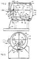
- a metallizing apparatus for vacuum metallizing an object 12 is generally illustrated at 10 in Figures 1 and 2.
- the object or substrate 12 to be metallized is of the type which includes a horizontal surface 14 and a vertical surface 16.
- the product formed may be an automobile exterior trim component, such as a bumper for a vehicle which is generally of an L-shaped configuration. It is to be understood that other types of objects and materials may be vacuum metallized and formed which are within the scope of the invention.
- the object 12 comprises an organic dielectric base or substrate having a smooth surface such as molded plastic.
- the metallized object 12 or product is particularly useful in the automotive application as an automobile exterior trim component to replace heavier and more expensive conventional chrome-plated metal parts.
- the substrate may be as the types set forth in United States Patent Number 4,431,711 discussed in the Background of the Invention.
- any suitable dielectric i.e, insulating material
- a castable or moldable plastic is used, preferably an elastomer that is tough and abuse resistant with some flexibility such as an injection molding grade thermal plastic polyurethane.
- suitable substrate materials are set forth in the referenced 4,431,711 patent.
- the apparatus 10 is utilized to deposit or collect a thin vacuum metallized layer of indium into electrically discrete islands, wherein the metal layer is corrosion resistant when adequately top coated, though the indium is a metal that is specially corrosion prone.
- the indium film is conductive as deposited because the metal nuclei initially deposited from the vapor phase are allowed to grow in molten phase only to a discrete island stage with the particles being electrically isolated from one another. The coating is kept quite thin and there is insufficient metal deposited to bring about coalescence of the metal particles and formation of an electrically conductive film.
- the indium layer generally has a nominal thickness less than 1000° A, preferably less than 600° A. By “nominal thickness” it is meant the thickness determined by the weight of metal deposited per unit area as if a continuous film.
- the metal film must be thick enough to reflect sufficient light to make the coated article 12 appear as a metal article, as set forth in the referenced patent.
- a resinous top coat is applied over the metal indium to improve resistance to mechanical abuse. Clear moisture resistant acrylic, urethane, and the like coating applied as a latex and more preferably as a solvent solution are suitable.
- the above deposition of indium film may be carried out by a variety of methods.
- the subject invention relates to vacuum deposition through thermal evaporation of the indium carried out at a vacuum of 5 X 10³ Torr or less.
- the apparatus of performing such vacuum deposition as illustrated and in the referenced 4,431,711 patent may be of the type used by Davidson Technology Center, a unit of Davidson Textron Inc., identified as a custom 1.22 m (48 inch) metallizer manufactured by K.H. Frederick Co.
- the apparatus 10 of the subject invention utilizes the prior art metallizer, though modified as subsequently discussed.
- the subject invention allows all vertical 16 and horizontal 14 surfaces to be metallized.
- the apparatus 10 includes a housing 18 forming a vacuum chamber 20 therein and having a door 22 hinged on hinge 23 for allowing access to the chamber 20 and sealable when closed at a joint 25 between the door 22 and the housing cylinder 18a.
- rotatable means 24 Within the chamber 20 is located rotatable means 24 having a horizontal axis A therethrough and adapted to rotatably support the object 12 for metallizing.
- the rotatable means 24 generally includes a rotatable carousel 26 with the axis A substantially at the center thereof.
- the rotatable carousel 26 includes a pair of circular end supports 27 with a plurality of support bars or reels 28 extending between the end supports 27 along the outer diameter thereof and parallel with the horizontal axis A.
- the support bars or reels 28 are rotatably secured to the end supports 27, by bearings 29 or the like.
- a plurality of hangers 30 are fixedly attached to the support bars 28 for supporting the object 12 thereto.
- the hangers 30 utilized to secure the object 12 to the reel 28 may include clips or fasteners to hold the object 12 thereto as commonly known in the art.
- the object 12 is mounted on the reel 28 so as to maintain the horizontal and vertical surfaces of the object 12 accordingly horizontal and vertical, respectively, to the axis.
- Drive means 31 is connected to the rotatable carousel 26 and optionally to the reels 28 for causing rotation of the carousel 26 during vaporization.
- the carousel 26 rotates causing rotation of the reels 28 in response thereto. In some applications, it is also desirable to cause independent rotation of the reels 28 along with the rotation of the carousel 26.
- the assembly includes first evaporation means 32 connected horizontally below the carousel 26 for containing and evaporating metal particles vertically toward the object 12 substantially to the horizontal surfaces 14.
- the first evaporation means 32 comprises a bus bar 34 longitudinally extending below the carousel 26 and parallel with the horizontal axis for receiving and transmitting a voltage.
- the bus bar 34 generally comprises two parallel members 34 with cross bars 36 therebetween.
- a plurality of elongated bowl shaped, metal boats 38 are connected across the cross bars 36 and to the bus bar 34.
- the boats 38 contain the metal to be evaporated, such as indium.
- the boats 38 are generally comprised of a tungsten material and may be of the type set forth in the referenced Patent Number 5,133,604.
- the bus bar 34 receives a voltage from a transformer 37 or the like, for a predetermined time which causes the evaporation of the metal particles and line of sight deposition of the metal particles onto the object 12 in the vacuum chamber 20 during periods when it is evacuated by a vacuum pump system 20a.
- This basic system herein before described is commonly known in the art and is of the type previously cited.
- the apparatus 10 is characterized by including second evaporation means 40 mounted vertically for containing and evaporating metal particles horizontally toward the object 12 and to the vertical surfaces 16 thereof.
- the second evaporation means 40 also comprises a bus bar having two parallel conductive arms 44 extending vertically toward the central axis A of the carousel 26.
- a conductive center cross bar 46 interconnects the parallel arms 44.
- the center cross bar 46 connects to a tubular evaporation boat 48 which contains metal to be vaporized, such as indium.
- the tubular boat 48 is generally tubular in shape with one open end 49 which is directed toward the end of the carousel 26 and towards the vertical surface 16 of the object 12.
- the boat 48 is electrically connected to the bus bar 44.
- the tubular boat 48 is slightly inclined, i.e., 5 degrees upwardly at open end 49, to insure that the metallizing indium does not flow out prior to the vacuum metallizing process.
- the metal within the boat 48 will vaporize and will be horizontally received on the object at the vertical surfaces 16 thereof when the chamber 20 is evacuated.
- any number of boats 38, 48 may be utilized.
- a plurality of boats 38 are electrically connected in series or series parallel horizontally below the carousel 26 extending less than the length of the reels 28.
- the number of tubular boats 48 generally depends on the length of the vertical surface 16 of object 12 and can vary from one to six boats.
- a method of vacuum metallizing an object 12 having a horizontal surface 14 and a vertical surface 16 includes steps of rotating the object 12 to be metallized about a horizontal axis, vacuum metallizing in a horizontal direction toward the vertical surface 16, and vacuum metallizing in a vertical direction toward the horizontal surface 14 to deposit metal thereon. Thereafter, a top coat is applied to the metallized object 12 for additional corrosion protection.
- an injection molded bumper of thermal plastic urethane is molded into a generally L-shaped configuration.
- a urethane enamel base coat is applied over the bumper.
- the pumping system for the apparatus 10 consists of a mechanical roughing pump, a silicone oil diffusion pump, and a liquid nitrogen cold trap to minimize water vapor and outgassing in the chamber 20.
- 1.0 grams of high purity indium is evaporated from eight 127 ⁇ m (5 mil) thick tungsten boats 38 connected in series to a 20 volt ac variable transformer.
- the four tubular tungsten boats 48 are connected in parallel to a 5 volt ac variable transformer and contain 0.3 grams.
- Eight boats 38 are located horizontally below and parallel with the carousel 28 or horizontal axis A. Power of 2.1 volts and 225 amperes was applied to the horizontal bus bar 34 for 2 minutes from a suitable low voltage power supply. Four tubular boats 48 were utilized and two each are placed and aligned at the end of each reel 28. Power supplied was 2.8 volts and 63 amperes for 2 minutes.
- the bumper 12 is rotated on the carousel at 20 rpm with source to substrate distance varying during rotation from 215.9 mm (8 1/2 inches) to 368.3 mm (14 1/2 inches.) This gives the metal thickness on the part of 350°A. Thereafter, a top coat is applied as discussed in the referenced patent.
Landscapes
- Chemical & Material Sciences (AREA)
- Chemical Kinetics & Catalysis (AREA)
- Engineering & Computer Science (AREA)
- Materials Engineering (AREA)
- Mechanical Engineering (AREA)
- Metallurgy (AREA)
- Organic Chemistry (AREA)
- General Chemical & Material Sciences (AREA)
- Physical Vapour Deposition (AREA)
Applications Claiming Priority (2)
| Application Number | Priority Date | Filing Date | Title |
|---|---|---|---|
| US856713 | 1992-01-24 | ||
| US07/856,713 US5198272A (en) | 1992-03-24 | 1992-03-24 | Thermal evaporation in two planes |
Publications (2)
| Publication Number | Publication Date |
|---|---|
| EP0558898A1 EP0558898A1 (en) | 1993-09-08 |
| EP0558898B1 true EP0558898B1 (en) | 1996-05-08 |
Family
ID=25324324
Family Applications (1)
| Application Number | Title | Priority Date | Filing Date |
|---|---|---|---|
| EP93100690A Expired - Lifetime EP0558898B1 (en) | 1992-01-24 | 1993-01-19 | Thermal evaporation in two planes |
Country Status (12)
| Country | Link |
|---|---|
| US (1) | US5198272A (cs) |
| EP (1) | EP0558898B1 (cs) |
| JP (1) | JP3434846B2 (cs) |
| KR (1) | KR960002634B1 (cs) |
| AU (1) | AU3203793A (cs) |
| CA (1) | CA2087151C (cs) |
| CZ (1) | CZ39593A3 (cs) |
| DE (1) | DE69302507T2 (cs) |
| ES (1) | ES2087571T3 (cs) |
| HU (1) | HU9300833D0 (cs) |
| MX (1) | MX9301562A (cs) |
| PL (1) | PL298216A1 (cs) |
Families Citing this family (11)
| Publication number | Priority date | Publication date | Assignee | Title |
|---|---|---|---|---|
| DE4201584C1 (cs) * | 1992-01-22 | 1993-04-15 | Leybold Ag, 6450 Hanau, De | |
| CH685348A5 (de) * | 1992-05-08 | 1995-06-15 | Balzers Hochvakuum | Vakuumbeschichtungsanlage mit drehgetriebenem Substratträger. |
| US5284679A (en) * | 1992-11-16 | 1994-02-08 | Davidson Textron Inc. | Method for making bright trim articles |
| JP2590438B2 (ja) * | 1994-06-30 | 1997-03-12 | 工業技術院長 | 薄膜形成方法および薄膜形成装置 |
| JPH09202963A (ja) | 1995-08-25 | 1997-08-05 | Abcor Inc | エッチングを行わずに金属化アイランド被覆製品を製造する方法 |
| US5558909A (en) * | 1996-01-17 | 1996-09-24 | Textron Automotive Interiors, Inc. | Apparatus and method for vacuum-metallizing articles with significant deposition onto three-dimensional surfaces |
| CA2316914C (en) * | 1997-12-31 | 2008-06-10 | Textron Systems Corporation | Metallized sheeting, composites, and methods for their formation |
| US20070028842A1 (en) * | 2005-08-02 | 2007-02-08 | Makoto Inagawa | Vacuum chamber bottom |
| JP4725589B2 (ja) * | 2008-03-25 | 2011-07-13 | ソニー株式会社 | 複合微粒子の製造装置及び製造方法 |
| JP2011058071A (ja) * | 2009-09-11 | 2011-03-24 | Sony Corp | 複合微粒子の製造装置、及び、複合微粒子の製造方法 |
| JP2013040357A (ja) * | 2011-08-11 | 2013-02-28 | Optorun Co Ltd | 成膜装置 |
Family Cites Families (9)
| Publication number | Priority date | Publication date | Assignee | Title |
|---|---|---|---|---|
| US4116161A (en) * | 1976-11-12 | 1978-09-26 | Mcdonnell Douglas Corporation | Dual tumbling barrel plating apparatus |
| US4431711A (en) * | 1980-03-25 | 1984-02-14 | Ex-Cell-O Corporation | Vacuum metallizing a dielectric substrate with indium and products thereof |
| CH650028A5 (de) * | 1980-09-26 | 1985-06-28 | Balzers Hochvakuum | Anordnung zum gleichfoermigen beschichten von rotationsflaechen durch bedampfen im hochvakuum. |
| JPS60129158A (ja) * | 1983-12-15 | 1985-07-10 | Toyoda Gosei Co Ltd | プラズマ処理装置 |
| CA1249926A (en) * | 1984-06-12 | 1989-02-14 | Katsuhide Manabe | Plasma processing apparatus |
| GB8718916D0 (en) * | 1987-08-10 | 1987-09-16 | Ion Tech Ltd | Thin film alloying apparatus |
| DD265175A1 (de) * | 1987-09-24 | 1989-02-22 | Hochvakuum Dresden Veb | Verfahren und einrichtung zur homogenen schichtabscheidung in vakuumanlagen |
| US5090350A (en) * | 1989-12-27 | 1992-02-25 | Xerox Corporation | Method and apparatus for cleaning, coating and curing receptor substrates in an enclosed planetary array |
| US5133604A (en) * | 1991-07-30 | 1992-07-28 | Davidson Textron Inc. | Method and apparatus for evaluating evaporating boats based on evaporation rate characteristics |
-
1992
- 1992-03-24 US US07/856,713 patent/US5198272A/en not_active Expired - Lifetime
-
1993
- 1993-01-12 CA CA002087151A patent/CA2087151C/en not_active Expired - Fee Related
- 1993-01-19 ES ES93100690T patent/ES2087571T3/es not_active Expired - Lifetime
- 1993-01-19 EP EP93100690A patent/EP0558898B1/en not_active Expired - Lifetime
- 1993-01-19 DE DE69302507T patent/DE69302507T2/de not_active Expired - Fee Related
- 1993-01-27 AU AU32037/93A patent/AU3203793A/en not_active Abandoned
- 1993-02-04 JP JP03923093A patent/JP3434846B2/ja not_active Expired - Fee Related
- 1993-03-10 CZ CZ93395A patent/CZ39593A3/cs unknown
- 1993-03-19 MX MX9301562A patent/MX9301562A/es not_active IP Right Cessation
- 1993-03-23 KR KR1019930004468A patent/KR960002634B1/ko not_active Expired - Fee Related
- 1993-03-23 HU HU9300833A patent/HU9300833D0/hu unknown
- 1993-03-24 PL PL29821693A patent/PL298216A1/xx unknown
Also Published As
| Publication number | Publication date |
|---|---|
| MX9301562A (es) | 1993-09-01 |
| JPH062111A (ja) | 1994-01-11 |
| DE69302507D1 (de) | 1996-06-13 |
| HU9300833D0 (en) | 1993-06-28 |
| JP3434846B2 (ja) | 2003-08-11 |
| DE69302507T2 (de) | 1996-11-28 |
| KR930019860A (ko) | 1993-10-19 |
| AU3203793A (en) | 1993-09-30 |
| CZ39593A3 (en) | 1994-04-13 |
| CA2087151A1 (en) | 1993-09-25 |
| KR960002634B1 (ko) | 1996-02-24 |
| CA2087151C (en) | 2002-08-20 |
| ES2087571T3 (es) | 1996-07-16 |
| EP0558898A1 (en) | 1993-09-08 |
| US5198272A (en) | 1993-03-30 |
| PL298216A1 (en) | 1993-10-04 |
Similar Documents
| Publication | Publication Date | Title |
|---|---|---|
| CA2087151C (en) | Thermal evaporation in two planes | |
| US4431711A (en) | Vacuum metallizing a dielectric substrate with indium and products thereof | |
| US5409782A (en) | Composite film | |
| EP0287208B1 (en) | Process for manufacturing a corrosion-resistant vacuum-metallized article by etching the metal layer and applying a clear resinous coating | |
| US5079101A (en) | Composite film | |
| EP1116801B1 (en) | Method of applying a coating by physical vapour deposition | |
| GB2031498A (en) | Multi-pane window structure | |
| CA1161316A (en) | Vacuum metallized articles | |
| JP3453174B2 (ja) | 光沢のある装備品を製造する方法 | |
| US4183975A (en) | Vacuum metallizing process | |
| US5558909A (en) | Apparatus and method for vacuum-metallizing articles with significant deposition onto three-dimensional surfaces | |
| US6821560B2 (en) | Surface-treating support member and method using the same | |
| EP0684082B1 (en) | Reduced solvent island coating system | |
| US20120128948A1 (en) | Coated article and method for manufacturing same | |
| Grantscharova et al. | Formation of texture in vacuum-condensed tin on glass | |
| US2413605A (en) | Process of evaporating metals | |
| KR970000191B1 (ko) | 복합막 | |
| Choi et al. | Electrodeposition of copper for ULSI metallization | |
| US20030091738A1 (en) | Vacuum deposition method, products thereof, and devices therefor | |
| Brocherieux et al. | XPS characterization of nickel films deposited on an acrylonitrile-butadiene-styrene copolymer | |
| Duchateau et al. | The Influence of Ion Impact on the Crystallization of Amorphous PdTa Films | |
| Beisswenger et al. | Apparatus for the Evaporative Coating of Substrates | |
| WO1997037053A1 (en) | Barrier films having vapor coated high energy surfaces | |
| GB2358196A (en) | Coating an organic article by physical vapour deposition with a chromium layer between the article and the coating | |
| MXPA96001824A (en) | Article that has a coat that simulates the lat |
Legal Events
| Date | Code | Title | Description |
|---|---|---|---|
| PUAI | Public reference made under article 153(3) epc to a published international application that has entered the european phase |
Free format text: ORIGINAL CODE: 0009012 |
|
| AK | Designated contracting states |
Kind code of ref document: A1 Designated state(s): DE ES FR GB IT NL |
|
| 17P | Request for examination filed |
Effective date: 19940204 |
|
| 17Q | First examination report despatched |
Effective date: 19941213 |
|
| GRAA | (expected) grant |
Free format text: ORIGINAL CODE: 0009210 |
|
| AK | Designated contracting states |
Kind code of ref document: B1 Designated state(s): DE ES FR GB IT NL |
|
| REF | Corresponds to: |
Ref document number: 69302507 Country of ref document: DE Date of ref document: 19960613 |
|
| REG | Reference to a national code |
Ref country code: ES Ref legal event code: BA2A Ref document number: 2087571 Country of ref document: ES Kind code of ref document: T3 |
|
| ITF | It: translation for a ep patent filed | ||
| REG | Reference to a national code |
Ref country code: ES Ref legal event code: FG2A Ref document number: 2087571 Country of ref document: ES Kind code of ref document: T3 |
|
| REG | Reference to a national code |
Ref country code: GB Ref legal event code: 727 |
|
| REG | Reference to a national code |
Ref country code: GB Ref legal event code: 727A |
|
| ET | Fr: translation filed | ||
| REG | Reference to a national code |
Ref country code: GB Ref legal event code: 727B |
|
| REG | Reference to a national code |
Ref country code: GB Ref legal event code: SP |
|
| PGFP | Annual fee paid to national office [announced via postgrant information from national office to epo] |
Ref country code: FR Payment date: 19970213 Year of fee payment: 5 |
|
| PGFP | Annual fee paid to national office [announced via postgrant information from national office to epo] |
Ref country code: NL Payment date: 19970218 Year of fee payment: 5 |
|
| PGFP | Annual fee paid to national office [announced via postgrant information from national office to epo] |
Ref country code: DE Payment date: 19970225 Year of fee payment: 5 |
|
| PGFP | Annual fee paid to national office [announced via postgrant information from national office to epo] |
Ref country code: GB Payment date: 19970226 Year of fee payment: 5 |
|
| PLBE | No opposition filed within time limit |
Free format text: ORIGINAL CODE: 0009261 |
|
| STAA | Information on the status of an ep patent application or granted ep patent |
Free format text: STATUS: NO OPPOSITION FILED WITHIN TIME LIMIT |
|
| PGFP | Annual fee paid to national office [announced via postgrant information from national office to epo] |
Ref country code: ES Payment date: 19970317 Year of fee payment: 5 |
|
| 26N | No opposition filed | ||
| NLT1 | Nl: modifications of names registered in virtue of documents presented to the patent office pursuant to art. 16 a, paragraph 1 |
Owner name: TEXTRON AUTOMOTIVE INTERIORS INC. |
|
| REG | Reference to a national code |
Ref country code: FR Ref legal event code: CD |
|
| REG | Reference to a national code |
Ref country code: ES Ref legal event code: PC2A |
|
| PG25 | Lapsed in a contracting state [announced via postgrant information from national office to epo] |
Ref country code: GB Free format text: LAPSE BECAUSE OF NON-PAYMENT OF DUE FEES Effective date: 19980119 |
|
| PG25 | Lapsed in a contracting state [announced via postgrant information from national office to epo] |
Ref country code: ES Free format text: LAPSE BECAUSE OF EXPIRATION OF PROTECTION Effective date: 19980120 |
|
| PG25 | Lapsed in a contracting state [announced via postgrant information from national office to epo] |
Ref country code: FR Free format text: THE PATENT HAS BEEN ANNULLED BY A DECISION OF A NATIONAL AUTHORITY Effective date: 19980131 |
|
| PG25 | Lapsed in a contracting state [announced via postgrant information from national office to epo] |
Ref country code: NL Free format text: LAPSE BECAUSE OF NON-PAYMENT OF DUE FEES Effective date: 19980801 |
|
| GBPC | Gb: european patent ceased through non-payment of renewal fee |
Effective date: 19980119 |
|
| NLV4 | Nl: lapsed or anulled due to non-payment of the annual fee |
Effective date: 19980801 |
|
| PG25 | Lapsed in a contracting state [announced via postgrant information from national office to epo] |
Ref country code: DE Free format text: LAPSE BECAUSE OF NON-PAYMENT OF DUE FEES Effective date: 19981001 |
|
| REG | Reference to a national code |
Ref country code: FR Ref legal event code: ST |
|
| REG | Reference to a national code |
Ref country code: ES Ref legal event code: FD2A Effective date: 20000301 |
|
| PGFP | Annual fee paid to national office [announced via postgrant information from national office to epo] |
Ref country code: IT Payment date: 20060131 Year of fee payment: 14 |
|
| PG25 | Lapsed in a contracting state [announced via postgrant information from national office to epo] |
Ref country code: IT Free format text: LAPSE BECAUSE OF NON-PAYMENT OF DUE FEES Effective date: 20070119 |