EP0556801B1 - Kühl/Schmiermittel-Zufuhrvorrichtung eines rotierenden Schaftwerkzeuges - Google Patents
Kühl/Schmiermittel-Zufuhrvorrichtung eines rotierenden Schaftwerkzeuges Download PDFInfo
- Publication number
- EP0556801B1 EP0556801B1 EP93102479A EP93102479A EP0556801B1 EP 0556801 B1 EP0556801 B1 EP 0556801B1 EP 93102479 A EP93102479 A EP 93102479A EP 93102479 A EP93102479 A EP 93102479A EP 0556801 B1 EP0556801 B1 EP 0556801B1
- Authority
- EP
- European Patent Office
- Prior art keywords
- sleeve
- shank
- coolant
- grooves
- head
- Prior art date
- Legal status (The legal status is an assumption and is not a legal conclusion. Google has not performed a legal analysis and makes no representation as to the accuracy of the status listed.)
- Expired - Lifetime
Links
- 239000002826 coolant Substances 0.000 title claims description 17
- 239000000314 lubricant Substances 0.000 title claims description 14
- 238000007493 shaping process Methods 0.000 claims description 6
- 239000004033 plastic Substances 0.000 claims description 3
- 229920003023 plastic Polymers 0.000 claims description 3
- 238000000465 moulding Methods 0.000 description 23
- 239000005068 cooling lubricant Substances 0.000 description 4
- 238000007654 immersion Methods 0.000 description 4
- 238000001816 cooling Methods 0.000 description 3
- 238000005520 cutting process Methods 0.000 description 3
- 230000000694 effects Effects 0.000 description 3
- 238000005461 lubrication Methods 0.000 description 3
- 238000004519 manufacturing process Methods 0.000 description 2
- 238000003801 milling Methods 0.000 description 2
- 230000007704 transition Effects 0.000 description 2
- 235000014676 Phragmites communis Nutrition 0.000 description 1
- 229910000831 Steel Inorganic materials 0.000 description 1
- 230000001419 dependent effect Effects 0.000 description 1
- 238000005516 engineering process Methods 0.000 description 1
- 238000003754 machining Methods 0.000 description 1
- 230000002028 premature Effects 0.000 description 1
- 239000010959 steel Substances 0.000 description 1
- 230000003313 weakening effect Effects 0.000 description 1
- 238000009736 wetting Methods 0.000 description 1
Images
Classifications
-
- B—PERFORMING OPERATIONS; TRANSPORTING
- B23—MACHINE TOOLS; METAL-WORKING NOT OTHERWISE PROVIDED FOR
- B23G—THREAD CUTTING; WORKING OF SCREWS, BOLT HEADS, OR NUTS, IN CONJUNCTION THEREWITH
- B23G5/00—Thread-cutting tools; Die-heads
- B23G5/005—Thread-cutting tools; Die-heads with lubrication or cooling devices
-
- B—PERFORMING OPERATIONS; TRANSPORTING
- B23—MACHINE TOOLS; METAL-WORKING NOT OTHERWISE PROVIDED FOR
- B23Q—DETAILS, COMPONENTS, OR ACCESSORIES FOR MACHINE TOOLS, e.g. ARRANGEMENTS FOR COPYING OR CONTROLLING; MACHINE TOOLS IN GENERAL CHARACTERISED BY THE CONSTRUCTION OF PARTICULAR DETAILS OR COMPONENTS; COMBINATIONS OR ASSOCIATIONS OF METAL-WORKING MACHINES, NOT DIRECTED TO A PARTICULAR RESULT
- B23Q1/00—Members which are comprised in the general build-up of a form of machine, particularly relatively large fixed members
- B23Q1/0009—Energy-transferring means or control lines for movable machine parts; Control panels or boxes; Control parts
- B23Q1/0018—Energy-transferring means or control lines for movable machine parts; Control panels or boxes; Control parts comprising hydraulic means
- B23Q1/0027—Energy-transferring means or control lines for movable machine parts; Control panels or boxes; Control parts comprising hydraulic means between moving parts between which an uninterrupted energy-transfer connection is maintained
- B23Q1/0036—Energy-transferring means or control lines for movable machine parts; Control panels or boxes; Control parts comprising hydraulic means between moving parts between which an uninterrupted energy-transfer connection is maintained one of those parts being a tool
Definitions
- the invention relates to a rotating shaft tool with a coolant / lubricant supply device, in which a molding head has grooves extending in the axial direction and is integral with a shaft via a groove outlet area and in which a main channel extending in the shaft and on the groove outlet area extends into branch channels at the end divides, each leading to one of the grooves and opening in this, with a roofing of the openings is provided, according to the preamble of claim 1.
- the branch channels and their mouths are provided in the region of the molding head with only a small distance from its front working end and the mouths are covered by the workpiece in which the molding head is working.
- the coolant / lubricant is advantageously brought directly to the end of work and prevented by the surrounding workpiece from free radial splashing out of the grooves.
- the provision of the two channels lies in the soul of the molding head, the cross section of which is relatively small because of the grooves and which is considerably weakened by the branch channels. Due to the weakening through the branch channels, the forming head of the shank tool breaks in a considerable number of cases when machining the workpiece.
- a shank tool of the type mentioned is known from DE-A-4 003 257.
- the outer diameter of the sleeve is significantly larger than the outer diameter of the forming head and the sleeve ends at a considerable distance in front of the forming head. Since the outer diameter of the sleeve is larger than the working outer diameter of the molding head, the depth of the immersion of the molding head in the workpiece is limited to the distance of the sleeve from the molding head.
- the coolant / lubricant can also fly radially away from the rotating tool in the region of this distance, which is not covered by the sleeve.
- the mouths of the two channels must also be at this distance, i.e. be the desired immersion depth from the die head.
- a rotating tool is also known (EP-A-0 430 536), in which the outer diameter of a sleeve, which sits on a tool jacket and covers axial channels, is smaller than the outer diameter of the forming head.
- the molding head is provided with slots which merge into slot outlet areas and the sleeve extends only as far as the slot outlet areas.
- the coolant / lubricant can fly radially away from the rotating tool in the area that is not covered by the sleeve.
- An object of the invention is therefore to provide a shaft tool of the type mentioned, in which the mouths of the branch channels are provided as close as possible to the forming head and yet at a distance from the forming head with a roof which does not impair the strength of the shaft tool.
- the shank tool according to the invention is to achieve this object, characterized in that the outer diameter of the sleeve is smaller than the outer diameter of the molding head and the sleeve extends towards the molding head, so that the coolant / lubricant from the sleeve (12) into the molding head grooves (6) flows.
- the proposed arrangement of the branch channels and their mouths avoids the risk of breakage of the core or the soul of the molding head and also the transition between the molding head and the slot outlet area.
- the distance between the branch channel mouths and the front working end of the molding head is sufficiently short to ensure usable cooling / lubrication at the working end.
- the roofing of the mouths is provided by the additional bushing, which deflects the coolant / lubricant emerging as radial jets in the axial direction, so that it flows over a short distance to the molding head, into the grooves and along the base of the grooves to the front working end can. If the forming head works in a blind hole, the coolant / lubricant will flow back into the grooves at a radial distance from the bottom of the grooves.
- the rifle is made of steel, for example, and is glued to the shaft. It is particularly expedient and advantageous if the bushing is made of a plastic and if the bushing has radial projections on the inside which snap radially into the recesses of the shank tool. This is an easy to manufacture and assemble sleeve.
- the main channel usually runs in the middle of the shaft.
- the main channel can extend to only part of the shaft or the entire length of the shaft.
- the distance between the mouths in front of the molding head is so large that the break-prone transition between the molding head and the groove outlet area is not affected.
- the mutes run e.g. straight or coiled.
- Shank tools are understood here as taps, milling cutters and taps, but also general milling cutters and reed bales.
- the rifle is led up to the forming head. It should be noted that if the outer diameter of the bushing is larger, the working outer diameter of the molding head, the bushing limits the depth of immersion of the molding head in the workpiece.
- the sleeve is a sleeve or a tube section, i.e.
- the wall thickness is relatively thin and the outside and inside have a substantially smooth surface. If the groove run-out area has the same outer diameter as the shaft, then it is limited to the grooves. If the neck is followed by a thinner neck than the shaft, which only partially receives the tapered grooves, then the groove outlet area means this neck.
- the coolant / lubricant can also flow from the sleeve along the groove-free neck until it enters the grooves.
- the rifle is usually held and supported only on the shaft.
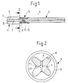
- the coolant / lubricant supply device is provided on a shank tool which is designed as a tap which has a shaping head 1 with a front working end 2.
- a groove outlet area 3 adjoins the molding head 1 and merges into a look 4.
- the outer diameter of the shaft 4 is smaller here than the outer diameter of the molding head 1.
- the molding head 1 carries mold spines 5 which extend in the longitudinal direction and are separated from one another by grooves 6.
- the grooves 6 also extend to the groove outlet area 3 at a shallower depth, which is due to the production technology.
- a core 7 remains in the center between the grooves 6.
- the tapering grooves 6 are separated by backs 8, the radial dimension of which is smaller than the radius of the shaft 4.
- a main channel 9, which ends in the groove outlet area 3, runs centrally and axially in the shaft 4. From the main channel 9, a branch channel 10, whose mouth 11 lies at the bottom of the groove, extends in the groove outlet area 3 per groove 6.
- a bushing 12 made of plastic is pushed onto the shaft 3, which extends to the advantage 1 and covers the mouths 11, i.e. radial distance from the mouths. Coolant / lubricant, which is supplied via the main channel 9 and the branch channels 10, emerges from the orifices 11 in the effective area of the bush 12 and is directed by the latter in the direction of the molding head 1.
- blind hole and through hole threads the following:
- the cooling lubrication effect is only guaranteed after reaching a certain immersion depth in the workpiece, since only then can the tool surface be adequately wetted by the coolant flowing back from the workpiece wall.
- the first tool revolutions in the workpiece there is often no sufficient cooling lubrication effect, which leads to premature tool wear.
Landscapes
- Engineering & Computer Science (AREA)
- Mechanical Engineering (AREA)
- Auxiliary Devices For Machine Tools (AREA)
- Drilling Tools (AREA)
- Drilling And Boring (AREA)
Description
- Die Erfindung betrifft ein rotierendes Schaftwerkzeug mit einer Kühl/Schmiermittel-Zufuhrvorrichtung, bei dem ein Formkopf sich in Achsrichtung erstreckende Nuten aufweist und über einen Nutenauslaufbereich mit einem Schaft einstückig ist und bei dem ein sich im Schaft und auf den Nutenauslaufbereich erstreckender Hauptkanal sich endseitig in Zweigkanäle aufteilt, die jeweils zu einer der Nuten führen und in dieser münden, wobei eine Überdachung der Mündungen vorgesehen ist, gemäß Oberbegriff des Patentanspruchs 1.
- Bei einer durch die Praxis bekannten Zufuhrvorrichtung sind die Zweigkanäle und deren Mündungen im Bereich des Formkopfes mit nur geringem Abstand von dessen vorderen Arbeitsende vorgesehen und sind die Mündungen von dem Werkstück überdacht, in dem der Formkopf arbeitet. Vorteilhafterweise wird das Kühl/Schmiermittel unmittelbar an das Arbeitsende gebracht und durch das umgebende Werkstück an einem freien radialen Wegspritzen aus den Nuten gehindert. Das Vorsehen der Zweikanäle in der Seele des Formkopfes liegen, deren Querschnitt wegen der Nuten relativ gering ist und die durch die Zweigkanäle erheblich geschwächt ist. Aufgrund der Schwächung durch die Zweigkanäle bricht der Formkopf des Schaftwerkzeuges in einer beachtlichen Zahl von Fällen beim Bearbeiten des Werkstückes.
- Ein Schaftwerkzeug der eingangs genannten Art ist durch die DE-A-4 003 257 bekannt. Bei dem bekannten Schaftwerkzeug ist der Außendurchmesser der Büchse deutlich größer als der Außendurchmesser des Formkopfes und endet die Büchse mit beträchtlichem Abstand vor dem Formkopf. Da der Außendurchmesser der Büchse größer ist als der Arbeitsaußendurchmesser des Formkopfes, ist die Tiefe des Eintauchens des Formkopfes in das Werkstück auf den Abstand der Büchse vom Formkopf begrenzt. Auch kann das Kühl/Schmiermittel im Bereich dieses Abstandes, der nicht von der Büchse überdeckt ist, radial von dem rotierenden Werkzeug wegfliegen. Die Mündungen der zwei Kanäle müssen auch um diesen Abstand, d.h. die erwünschte Eintauchtiefe vom Formkopf entfernt sein.
- Es ist auch ein rotierendes Werkzeug bekannt (EP-A-0 430 536), bei dem der Außendurchmesser einer Büchse, welche auf einem Werkzeugmantel sitzt und axiale Kanäle überdacht, kleiner ist als der Außendurchmesser des Formkopfes. Der Formkopf ist mit Schlitzen versehen, die in Schlitzauslaufbereiche übergehen und die Büchse erstreckt sich nur bis zu den Schlitzauslaufbereichen. Auch hier kann das Kühl/Schmiermittel in dem Bereich, der nicht von der Büchse überdeckt ist, radial von dem rotierenden Werkzeug wegfliegen.
- Eine Aufgabe der Erfindung ist es daher, ein Schaftwerkzeug der eingangs genannten Art zu schaffen, bei dem die Mündungen der Zweigkanäle möglichst nahe dem Formkopf und dennoch in einer die Festigkeit des Schaftwerkzeuges nicht beeinträchtigenden Ferne vom Formkopf mit Überdachung vorgesehen sind. Das erfindungsgemäße Schaftwerkzeug ist, diese Aufgabe lösend, dadurch gekennzeichnet, daß der Außendurchmesser der Büchse kleiner als der Außendurchmesser des Formkopfes ist und die Büchse sich zum Formkopf hin erstreckt, so daß das Kühl/Schmiermittel von der Büchse (12) in die Formkopf-Nuten (6) strömt. Durch die vorgesehene Anordnung der Zweigkanäle und deren Mündungen ist die Bruchgefährdung des Kernes bzw. der Seele des Formkopfes und auch des Überganges zwischen Formkopf und Nutenauslaufbereich vermieden. Andererseits ist die Entfernung zwischen den Zweigkanal-Mündungen und dem vorderen Arbeitsende des Formkopfes ausreichend kurz, um eine brauchbare Kühl/Schmierung am Arbeitsende zu gewährleisten. Die Überdachung der Mündungen ist durch die zusätzliche Büchse gegeben, welche das als radiale Strahlen austretende Kühl/Schmiermittel in axialer Richtung umlenkt, so daß es über eine kurze Wegstrecke zu dem Formkopf, in die Nuten und entlang dem Grund der Nuten zu dem vorderen Arbeitsende strömen kann. Wenn der Formkopf in einen Sackloch arbeitet, dann wird das Kühl/Schmiermittel mit radialen Abstand von Grund der Nuten in diesen zurückströmen.
- Die Büchse ist z.B. aus Stahl und an Schaft angeklebt. Besonders zweckmäßig und vorteilhaft ist es, wenn die Büchse aus einem Kunststoff besteht und wenn dabei die Büchse innen radiale Vorsprünge aufweist, die in Ausnehmungen des Schaftwerkzeuges federnd eingeschnappt radial einrasten. Dies ist eine einfach herstellbare und montierbare Büchse.
- In der Regel verläuft der Hauptkanal mittig in Schaft. Der Hauptkanal kann sich auf nur einen Teil des Schaftes oder die ganze Länge des Schaftes erstrecken. Der Abstand der Mündungen vorn Formkopf ist so groß, daß der bruchgefährdete Übergang zwischen Formkopf und Nutenauslaufbereich nicht beeinflußt wird. Die Muten verlaufen z.B. geradlinig oder gewendelt. Unter Schaftwerkzeugen werden hier verstanden Gewindebohrer, -fräser und -furcher, aber auch allgemeine Fräser und Reibaalen. Die Büchse ist bis zum Formkopf geführt. Dabei ist zu beachten, daß dann, wenn der Außendurchmesser der Büchse größer ist, sie der Arbeiteaußendurchmesser des Formkopfes, die Büchse die Tiefe des Eintauchens des Formkopfes in das Werkstück begrenzt. Die Büchse ist eine Hülse bzw. ein Rohrabschnitt, d.h. in der Wanddicke relativ dünn und außen sowie innen mit in wesentlichen glatter Oberfläche. Wenn der Nutenauslaufbereich den gleichen Außendurchmesser wie der Schaft hat, dann ist er auf die Nuten begrenzt. Wenn sich an den Formkopf ein gegenüber dem Schaft dünnerer Hals anschließt, der nur teilweise die auslaufenden Nuten aufnimmt, dann ist mit Nutenauslaufbereich dieser Hals gemeint. Das Kühl/Schmiermittel kann von der Büchse auch entlang nutenfreiem Hals fließen, bis es in die Nuten eintritt. Die Büchse ist in der Regel nur am Schaft gehalten und abgestützt.
- In der Zeichnung ist eine bevorzugte Ausführungsform der Erfindung dargestellt und zeigt
- Fig. 1
- einen Längsschnitt einer Kühl/Schmiermittel-Zufuhrvorrichtung eines rotierenden Schaftwerkzeuges und
- Fig. 2
- einen Schnitt gemäß Linie II-II in Fig. 1 in einen gegenüber Fig. 1 vergrößerten Maßstab.
- Die Kühl/Schmiermittel-Zufuhrvorrichtung gemäß Zeichnung ist an einem Schaftwerkzeug vorgesehen, das als Gewindebohrer ausgebildet ist, der einen Formkopf 1 mit einem vorderen Arbeitsende 2 aufweist. An den Formkopf 1 schließt sich ein Nutenauslaufbereich 3 an, der in einen Schaut 4 übergeht. Der Außendurchmesser des Schaftes 4 ist hier kleiner als dar Außendurchmesser des Formkopfes 1. Der Formkopf 1 trägt sich in Längsrichtung erstreckende Formrücken 5, die durch Nuten 6 voneinander getrennt sind. Die Nuten 6 erstrecken sich bei geringerer Tiefe auch auf den Nutenauslaufbereich 3, was fertigungstechnisch bedingt ist. Im Bereich des Formkopfes 1 bleibt mittig zwischen den Nuten 6 eine Seele 7. Im Nutenauslaufbereich sind die auslaufenden Nuten 6 durch Rücken 8 getrennt, deren radiale Abmessung kleiner ist als der Radius des Schaftes 4.
- Mittig und axial verläuft im Schaft 4 ein Hauptkanal 9, der im Nutenauslaufbereich 3 endet. Von dem Hauptkanal 9 geht im Nutenauslaufbereich 3 pro Nut 6 ein Zweigkanal 10 ab, dessen Mündung 11 am Grund der Nut liegt. Auf den Schaft 3 ist eine Büchse 12 aus Kunststoff geschoben, die sich zum Vorteil 1 hin erstreckt und die Mündungen 11 überdacht, d.h. radialen Abstand von den Mündungen hat. Kühl/Schmiermittel, das über den Hauptkanal 9 und die Zweigkanäle 10 zugeführt wird, tritt aus den Mündungen 11 im Wirkungsbereich der Büchse 12 aus und wird von dieser in Richtung zum Formkopf 1 gelenkt.
- Generell gilt für Grundloch- und Durchgangslochgewinde folgendes:
Bei Werzeugen mit innerer Kühlschmiermittelzufuhr mit Austritt im Ausschnittbereich in den Nuten oder stirnseitig im Werkzeug ist die Kühlschmierwirkung immer erst nach Erreichen einer gewissen Eintauchtiefe in das Werkstück gewährleistet, da erst dann durch Zurückfließen des Kühlschmiermittels von der Werkstückwand eine ausreichende Benetzung der Werkzeugoberfläche gewährleistet ist. Bei den ersten Werkzeugumdrehungen im Werkstück ist oft keine ausreichende Kühlschmierwirkung vorhanden, was zu vorzeitigem Werkzeugverschleiß führt. - Die Umlenkung des radial austretenden Kühlschmiermittelstrahls an der Büches in axiale Richtung führt trotz der schnittgeschwindigkeitsabhängigen Fliehkräfte zu einer konstanten Benetzung bzw. Ummantelung des Schneidteils mit dem Külschmiermittel. Im Moment des Anschneidens (des Eintretens des Werkzeuges in das Werkstück) ist deshalb eine gesicherte Kühlschmiermittelwirkung garantiert. Dies ist ein wesentlicher Vorteil dieser Ausführung.
- Der Rückfluß des Kühlschmiermittels bei Durchgangslochgewinde spielt keine Rolle. Bei Grundlochgewinde wird der Rückfluß des Kühlschmiermittels durch die aufgeschobene Büchse nicht oder nur unwesentlich behindert, da zwischen Büchse und Bohrung sowieso ausreichend Raum für den Späneaustritt bleiben muß.
Claims (3)
- Rotierendes Schaftwerkzeug mit einer Kühl/Schmiermittel-Zufuhrvorrichtung,
bei dem ein Formkopf (1) sich in Achsrichtung erstreckende Nuten (6) aufweist und über einen Nutenauslaufbereich (3) mit einem Schaft (4) einstückig ist,
bei dem ein sich im Schaft (4) und auf den Nutenauslaufbereich (3) erstreckender Hauptkanal (9) sich endseitig in Zweigkanäle (10) aufteilt, die jeweils zu einer der Nuten führen und in dieser münden, wobei eine Überdachung (12) der Mündungen (11) vorgesehen ist, und
bei dem die Zweigkanäle (10) und deren Mündungen (11) mit Abstand vom Formkopf (1) im Nutenauslaufbereich (3) vorgesehen sind und eine auf dem Schaft (4) festsitzende Büchse (12) den Nutenauslaufbereich (3) und die Mündungen (11) überdacht und in Richtung zum Formkopf (1) hin offen ist,
dadurch gekennzeichnet,
daß der Außendurchmesser der Büchse (12) kleiner als der Außendurchmesser des Formkopfes (1) ist und die Büchse (12) sich zum Formkopf (1) hin erstreckt, sodaß das Kühl/Schmiermittel von der Büchse (12) in die Formkopf-Nuten (6) strömt. - Schaftwerkzeug nach Anspruch 1, dadurch gekennzeichnet, daß die Büchse (12) aus einem Kunststoff besteht.
- Schaftwerkzeug nach Anspruch 2, dadurch gekennzeichnet, daß die Büchse innen radiale Vorsprünge aufweist, die in Ausnehmungen des Schaftwerkzeuges federnd eingeschnappt radial einrasten.
Applications Claiming Priority (2)
| Application Number | Priority Date | Filing Date | Title |
|---|---|---|---|
| DE4205007A DE4205007A1 (de) | 1992-02-19 | 1992-02-19 | Kuehl/schmiermittel-zufuhrvorrichtung eines rotierenden schaftwerkzeuges |
| DE4205007 | 1992-02-19 |
Publications (2)
| Publication Number | Publication Date |
|---|---|
| EP0556801A1 EP0556801A1 (de) | 1993-08-25 |
| EP0556801B1 true EP0556801B1 (de) | 1995-11-08 |
Family
ID=6452078
Family Applications (1)
| Application Number | Title | Priority Date | Filing Date |
|---|---|---|---|
| EP93102479A Expired - Lifetime EP0556801B1 (de) | 1992-02-19 | 1993-02-17 | Kühl/Schmiermittel-Zufuhrvorrichtung eines rotierenden Schaftwerkzeuges |
Country Status (2)
| Country | Link |
|---|---|
| EP (1) | EP0556801B1 (de) |
| DE (2) | DE4205007A1 (de) |
Families Citing this family (9)
| Publication number | Priority date | Publication date | Assignee | Title |
|---|---|---|---|---|
| DE19522141B8 (de) * | 1994-07-02 | 2004-07-08 | August Beck Gmbh & Co | Rotierendes Schaftwerkzeug |
| FR2721848B1 (fr) * | 1994-07-02 | 1997-12-05 | Beck August Gmbh Co | Outil d'usinage rotatif |
| DE19544556A1 (de) | 1995-11-29 | 1997-06-05 | Beck August Gmbh Co | Rotierendes Schaftwerkzeug |
| DE19612104A1 (de) * | 1996-03-27 | 1997-10-02 | Komet Stahlhalter Werkzeug | Bohrwerkzeug für Werkzeugmaschinen sowie Verfahren zu dessen Herstellung |
| DE19754518C2 (de) * | 1997-12-09 | 2001-06-13 | Fette Wilhelm Gmbh | Kombination aus Gewindebohrer oder -former und dazugehöriger Adapterhülse für die Minimalmengenschmierung |
| DE10121986B4 (de) * | 2001-05-05 | 2007-01-11 | Iscar Ltd. | Mehrschneiden-Reibahle mit innerer Kühlmittelzufuhr |
| EP2266751A1 (de) | 2003-10-14 | 2010-12-29 | Gühring, Jörg | Schaftwerkzeug und zugeordnete Kühl-/Schmiermitteleinspeisestelle |
| DE102013205026A1 (de) | 2013-03-21 | 2014-09-25 | Gühring KG | Drehangetriebenes Schaftwerkzeug |
| JP7700062B2 (ja) * | 2022-02-04 | 2025-06-30 | 京セラ株式会社 | 回転工具及び切削加工物の製造方法 |
Citations (1)
| Publication number | Priority date | Publication date | Assignee | Title |
|---|---|---|---|---|
| EP0430536A2 (de) * | 1989-11-25 | 1991-06-05 | Omi Kogyo Co., Ltd. | Hohlbohrer |
Family Cites Families (5)
| Publication number | Priority date | Publication date | Assignee | Title |
|---|---|---|---|---|
| FR2239849A7 (en) * | 1973-08-02 | 1975-02-28 | Satomeca Ets | Tool holder for high speed cutting machine - has in-built lubricant liquid distributing channels |
| US4640652A (en) * | 1986-06-30 | 1987-02-03 | Scully-Jones Corp. | Coolant delivery system |
| DE4003257A1 (de) * | 1990-02-03 | 1991-08-08 | Fette Wilhelm Gmbh | Maschinenwerkzeug, insbesondere maschinengewindebohrer |
| DE4019428C2 (de) * | 1990-06-19 | 1997-07-03 | Fette Wilhelm Gmbh | Drehantreibbares Schaftwerkzeug |
| DE9006846U1 (de) * | 1990-06-19 | 1990-08-23 | Wilhelm Fette Gmbh, 2053 Schwarzenbek | Schaftförmiges Maschinenwerkzeug, insbesondere Maschinengewindebohrer |
-
1992
- 1992-02-19 DE DE4205007A patent/DE4205007A1/de not_active Withdrawn
-
1993
- 1993-02-17 DE DE59300870T patent/DE59300870D1/de not_active Expired - Fee Related
- 1993-02-17 EP EP93102479A patent/EP0556801B1/de not_active Expired - Lifetime
Patent Citations (1)
| Publication number | Priority date | Publication date | Assignee | Title |
|---|---|---|---|---|
| EP0430536A2 (de) * | 1989-11-25 | 1991-06-05 | Omi Kogyo Co., Ltd. | Hohlbohrer |
Also Published As
| Publication number | Publication date |
|---|---|
| DE59300870D1 (de) | 1995-12-14 |
| EP0556801A1 (de) | 1993-08-25 |
| DE4205007A1 (de) | 1993-08-26 |
Similar Documents
| Publication | Publication Date | Title |
|---|---|---|
| DE69808261T2 (de) | Werkzeug zum herstellen von innengewinde | |
| EP3285948B1 (de) | Drehwerkzeug mit sich verjüngendem kühlmittelkanal sowie versetzt angeordneten kühlmittelaustrittsleitungen und diesbezügliches herstellverfahren | |
| DE69621030T3 (de) | Böhrer mit Kühlkanälen und Verfahren zu seiner Herstellung | |
| AT396663B (de) | Spannbüchse, insbesondere federnde klemmhülse | |
| DE69101365T2 (de) | Vorrichtung zum Bohren mit verbesserter Späneabfuhr. | |
| EP1407848B1 (de) | Gewindewerkzeug mit Kühlmittelzufuhr | |
| EP0956920B2 (de) | Futter für drehantreibbare Werkzeuge, insbesondere Bohrer, Gewindebohrer o.dgl. | |
| DE4200808C2 (de) | Bearbeitungseinheit mit einer angetriebenen rotierenden Spindel | |
| DE10012810A1 (de) | Wälzkörpergewindetrieb mit radial eingesetztem Umlenkelement | |
| EP0891238B1 (de) | Bohrwerkzeug für werkzeugmaschinen sowie verfahren zu dessen herstellung | |
| EP2664400B1 (de) | Schneidwerkzeug | |
| DE102013205026A1 (de) | Drehangetriebenes Schaftwerkzeug | |
| EP2448704B1 (de) | Tieflochbohrer | |
| DE4003257C2 (de) | ||
| CH690026A5 (de) | Rotierendes Schaftwerkzeug. | |
| EP0556801A1 (de) | Kühl/Schmiermittel-Zufuhrvorrichtung eines rotierenden Schaftwerkzeuges | |
| DE3307555C2 (de) | Bohrungs-Nachbearbeitungswerkzeug | |
| DE10164878C5 (de) | Anordnung zur Einspeisung von Kühl- bzw. Schmiermittel in Werkzeuge | |
| DE10339518A1 (de) | Bohrwerkzeug mit Wechselschneidplatten sowie Wechselschneidplatten für ein solches Bohrwerkzeug | |
| DE4307280A1 (de) | Werkzeughalter | |
| EP0888842A1 (de) | Rotierendes Schaftwerkzeug | |
| EP0768136A1 (de) | Werkzeug mit innenliegender Kühlmittelzufuhr | |
| DE3315294A1 (de) | Schneidwerkzeug | |
| DE69218350T2 (de) | Konische Reibahle | |
| DE19522141C2 (de) | Rotierendes Schaftwerkzeug |
Legal Events
| Date | Code | Title | Description |
|---|---|---|---|
| PUAI | Public reference made under article 153(3) epc to a published international application that has entered the european phase |
Free format text: ORIGINAL CODE: 0009012 |
|
| AK | Designated contracting states |
Kind code of ref document: A1 Designated state(s): AT BE CH DE DK ES FR GB GR IE IT LI LU MC NL PT SE |
|
| RBV | Designated contracting states (corrected) |
Designated state(s): CH DE ES FR GB IT LI NL SE |
|
| 17P | Request for examination filed |
Effective date: 19931210 |
|
| 17Q | First examination report despatched |
Effective date: 19940810 |
|
| GRAA | (expected) grant |
Free format text: ORIGINAL CODE: 0009210 |
|
| AK | Designated contracting states |
Kind code of ref document: B1 Designated state(s): CH DE ES FR GB IT LI NL SE |
|
| PG25 | Lapsed in a contracting state [announced via postgrant information from national office to epo] |
Ref country code: NL Free format text: LAPSE BECAUSE OF FAILURE TO SUBMIT A TRANSLATION OF THE DESCRIPTION OR TO PAY THE FEE WITHIN THE PRESCRIBED TIME-LIMIT Effective date: 19951108 Ref country code: ES Free format text: THE PATENT HAS BEEN ANNULLED BY A DECISION OF A NATIONAL AUTHORITY Effective date: 19951108 |
|
| REF | Corresponds to: |
Ref document number: 59300870 Country of ref document: DE Date of ref document: 19951214 |
|
| GBT | Gb: translation of ep patent filed (gb section 77(6)(a)/1977) |
Effective date: 19960106 |
|
| ITF | It: translation for a ep patent filed | ||
| PG25 | Lapsed in a contracting state [announced via postgrant information from national office to epo] |
Ref country code: SE Effective date: 19960208 |
|
| PG25 | Lapsed in a contracting state [announced via postgrant information from national office to epo] |
Ref country code: LI Free format text: LAPSE BECAUSE OF NON-PAYMENT OF DUE FEES Effective date: 19960228 Ref country code: CH Free format text: LAPSE BECAUSE OF NON-PAYMENT OF DUE FEES Effective date: 19960228 |
|
| ET | Fr: translation filed | ||
| NLV1 | Nl: lapsed or annulled due to failure to fulfill the requirements of art. 29p and 29m of the patents act | ||
| PLBE | No opposition filed within time limit |
Free format text: ORIGINAL CODE: 0009261 |
|
| STAA | Information on the status of an ep patent application or granted ep patent |
Free format text: STATUS: NO OPPOSITION FILED WITHIN TIME LIMIT |
|
| REG | Reference to a national code |
Ref country code: CH Ref legal event code: PL |
|
| 26N | No opposition filed | ||
| PGFP | Annual fee paid to national office [announced via postgrant information from national office to epo] |
Ref country code: GB Payment date: 20000127 Year of fee payment: 8 |
|
| PGFP | Annual fee paid to national office [announced via postgrant information from national office to epo] |
Ref country code: FR Payment date: 20000215 Year of fee payment: 8 |
|
| PGFP | Annual fee paid to national office [announced via postgrant information from national office to epo] |
Ref country code: DE Payment date: 20000321 Year of fee payment: 8 |
|
| PG25 | Lapsed in a contracting state [announced via postgrant information from national office to epo] |
Ref country code: GB Free format text: LAPSE BECAUSE OF NON-PAYMENT OF DUE FEES Effective date: 20010217 |
|
| GBPC | Gb: european patent ceased through non-payment of renewal fee |
Effective date: 20010217 |
|
| PG25 | Lapsed in a contracting state [announced via postgrant information from national office to epo] |
Ref country code: FR Free format text: LAPSE BECAUSE OF NON-PAYMENT OF DUE FEES Effective date: 20011031 |
|
| REG | Reference to a national code |
Ref country code: FR Ref legal event code: ST |
|
| PG25 | Lapsed in a contracting state [announced via postgrant information from national office to epo] |
Ref country code: DE Free format text: LAPSE BECAUSE OF NON-PAYMENT OF DUE FEES Effective date: 20011201 |
|
| PG25 | Lapsed in a contracting state [announced via postgrant information from national office to epo] |
Ref country code: IT Free format text: LAPSE BECAUSE OF NON-PAYMENT OF DUE FEES;WARNING: LAPSES OF ITALIAN PATENTS WITH EFFECTIVE DATE BEFORE 2007 MAY HAVE OCCURRED AT ANY TIME BEFORE 2007. THE CORRECT EFFECTIVE DATE MAY BE DIFFERENT FROM THE ONE RECORDED. Effective date: 20050217 |