EP0556645B1 - Hammer mill - Google Patents
Hammer mill Download PDFInfo
- Publication number
- EP0556645B1 EP0556645B1 EP19930101680 EP93101680A EP0556645B1 EP 0556645 B1 EP0556645 B1 EP 0556645B1 EP 19930101680 EP19930101680 EP 19930101680 EP 93101680 A EP93101680 A EP 93101680A EP 0556645 B1 EP0556645 B1 EP 0556645B1
- Authority
- EP
- European Patent Office
- Prior art keywords
- impact
- tools
- pulveriser
- rotation
- impact tools
- Prior art date
- Legal status (The legal status is an assumption and is not a legal conclusion. Google has not performed a legal analysis and makes no representation as to the accuracy of the status listed.)
- Expired - Lifetime
Links
Images


Classifications
-
- B—PERFORMING OPERATIONS; TRANSPORTING
- B02—CRUSHING, PULVERISING, OR DISINTEGRATING; PREPARATORY TREATMENT OF GRAIN FOR MILLING
- B02C—CRUSHING, PULVERISING, OR DISINTEGRATING IN GENERAL; MILLING GRAIN
- B02C13/00—Disintegrating by mills having rotary beater elements ; Hammer mills
- B02C13/26—Details
- B02C13/282—Shape or inner surface of mill-housings
- B02C13/284—Built-in screens
-
- B—PERFORMING OPERATIONS; TRANSPORTING
- B02—CRUSHING, PULVERISING, OR DISINTEGRATING; PREPARATORY TREATMENT OF GRAIN FOR MILLING
- B02C—CRUSHING, PULVERISING, OR DISINTEGRATING IN GENERAL; MILLING GRAIN
- B02C13/00—Disintegrating by mills having rotary beater elements ; Hammer mills
- B02C13/14—Disintegrating by mills having rotary beater elements ; Hammer mills with vertical rotor shaft, e.g. combined with sifting devices
Definitions
- the invention relates to an impact mill for grinding granular products by means of impact tools attached to a rotor.
- the rotor and the striking tools are located inside a housing.
- the ground material passes through at least one inlet opening into a grinding chamber which receives the striking tools, in which grinding material shrinkage takes place when ground material strikes the striking tools and a boundary, which partially consists of a sieve and delimits the grinding chamber.
- the fine fraction produced during grinding passes through the sieve to at least one outlet opening in the housing.
- DE-U-88 10 234 describes a mill, in particular a hammer mill for comminuting peat and soil. It essentially consists of a vertical drive shaft, to which tools are attached, which are surrounded by a vertically displaceable grinding cassette. A filling opening is arranged concentrically above the tools. By lifting or lowering the grinding cassette, the grinding fineness should be adjustable. The downward drive of the drive shaft is disadvantageous with regard to contamination.
- DE-OS 36 36 869 describes a blow bar mill in which the material is fed from a feed device mounted on the top of the mill, which is fed into a circular and cylindrical sieve with a vertical axis, a solid bottom and a lid with an opening for the Feeding device limited grinding chamber opens.
- a blow bar rotor is rotatable about its vertical axis.
- the bottom of the grinding chamber contains an opening in the area of the vertical axis.
- the grinding chamber is arranged in a flour box. With the opening in the bottom of the grinding chamber, the formation of dust should be reduced and at the same time the degree of filling of the flour box should be increased. However, this effect, attributed to the bottom opening, can only be achieved to a limited extent.
- DE-U-88 04 662 discloses a beater mill with a beater mill housing delimiting a grinding chamber, in which a vertical rotor is provided, which is provided with a plurality of beater tools, with at least one inlet opening on the top of the beater mill housing and above the beater tools, whereby the striking tools in the direction of the axis of rotation lie essentially in the same plane as the axis of rotation, and a sieve arranged at least radially outside the striking tools for separating a fine fraction from a coarse fraction of the ground material fed to the striking mill and processed by the striking tools, and on the underside of the Impact mill housing at least one outlet opening is provided.
- the fine fraction must be separated from the outside air by means of a filter (see e.g. filter bags according to DE-U-88 04 622) and the ground material must be discharged from the negative pressure area by means of locks.
- a filter see e.g. filter bags according to DE-U-88 04 622
- the ground material must be discharged from the negative pressure area by means of locks.
- the disadvantages of the filters and locks are high equipment and maintenance costs, as well as additional energy consumption. In most cases there are also problems with the disposal of the exhaust air.
- the object of the invention is now to improve a beater mill of the type mentioned at the outset, wherein it preferably also does not require any aspiration which drives the regrind flow and thus does not require any outside air in the regrind in the grinding chamber.
- the radial arrangement of lamellas in a ring area also results in a significant reduction in energy consumption because these measures counteract the problem of entraining particles in the grinding chamber and result in a faster discharge of the finished particles.
- an impact mill preferably comprises a heavy part separating device.
- a circulating air separating device allows heavy parts to be separated without subsequently supplying the outside air together with the regrind to the grinding chamber. This means that it is also possible to use regrind when removing heavy parts to allow a high density to flow into the grinding chamber, whereby the problems of aspiration described above are avoided due to the use of circulating air.
- An impact mill according to the invention is distinguished by a high throughput of ground material with low energy consumption and maintenance expenditure.
- This high throughput is due to simple structural features, such as a graded radial expansion of the striking tools and / or essentially radially oriented, For example, lamella-like projections of the housing wall over the striking tools.
- the sieve acting as a barrier (sieve basket)
- the fine parts are discharged quickly. Thanks to the effect of these inexpensive features, expensive aspiration, filter and lock devices can be dispensed with.
- the hammer mill housing can also be made round around the rotor axis of rotation with a radius which is only slightly larger than the length from the axis of rotation to the ends of the most extensive percussion tools. Thanks to the compact design, an impact mill according to the invention takes up little space.
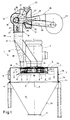
- An exemplary embodiment of an impact mill 1 according to FIG. 1 consists of a housing 2 on which a motor 3 is placed.
- the motor 3 serves as a drive for a rotor 4 within the housing 2, which rotates about an essentially vertical axis of rotation 5.
- striking tools 6 are fastened radially on the outside about pivot axes which are essentially parallel to the axis of rotation.
- the striking tools 6 are preferably arranged in different groups in the direction of the axis of rotation, the striking tools 6 of a group lying essentially in the same plane perpendicular to the axis of rotation.
- An essential feature according to the invention is that at least the radially outer ends of the striking tools of the uppermost group are less far outwards than those of at least one lower group.
- different percussion tool outer radii are generated by percussion tools 6 ′, 6 ′′, 6 ′′ ′′ of different lengths, but they could possibly also be generated by attaching the same percussion tools to different radii of the rotor.
- the outer radius of the uppermost group preferably smaller, but the groups below have outer radii which increase from group to group (6 ', 6' ', 6' '') downwards or, if necessary, remain constant.
- a conical surface 17, which essentially leads through the free ends of the striking tools of the various groups, has an opening angle 18 to the axis of rotation 5 which is greater than 0 ° and less than 25 °, but is preferably in the range from 5 ° to 20 ° .
- the graded length of the percussion tool outer radii enables a significantly higher throughput, because this feature reduces the resistance for the regrind when entering the area of the percussion tools.
- a sieve 7 surrounds the rotor 4 together with the striking tools 6 laterally and below and connects with the upper edge to the housing 2 in a form-fitting manner. It is preferably a cylindrical beaker sieve 7, consisting of a jacket wall 7a and an end wall 7b, of which walls at least one, but preferably both, are perforated.
- the sieve 7 is carried by a sieve holder 8. To replace the screen 7, the holder 8 is lowered so that the screen 7 can be removed from the housing 2 through a closable opening 9.
- the interior of the housing 2 is divided by the sieve 7 into two subspaces, namely into a grinding chamber 10, in which the rotor is located, and into a collecting chamber 11, in which the ground product collects. At the lower end of the collecting space 11 there is at least one outlet opening 12 from which the ground product can flow out due to gravity.
- the housing 2 consists essentially of two parts, a lower conical collecting part 2b and an upper, preferably cylindrical, grinding chamber part, the grinding chamber 10, the sieve 7 and a fine part outlet area 13 surrounding the sieve 7 2a. Vibration-damping seals 14 are preferably provided between the two housing parts 2a and 2b.
- the product to be ground is introduced into the grinding chamber 10 through at least one opening 15, which is arranged in the housing 2 directly above the striking tools 6.
- three openings 15 are provided with respect to the axis of rotation 5, offset by essentially 90 °.
- slats 16 are attached to the inner wall of the housing, which stand down and are aligned substantially along a line through the axis of rotation 5.
- the slats 16 are located directly above the striking tools 6, so that only a narrow gap remains open between the lower edges of the slats 16 and the striking tools of the uppermost group.
- the features according to the invention minimize the co-rotating and radially pent-up regrind layer by the lamellas 16 forming an additional impact surface on which the co-rotating regrind is comminuted and deflected and thus subjected to a further impact on a striking tool 6 in order to subsequently hit the circumferential surface 7a already comminuted. Since the regrind already contains an increased proportion of fines when this occurs, an increased proportion of the regrind escapes through the sieve holes, so that a smaller impact pressure and a smaller build-up develop can.
- the regrind can also strike lower groups of striking tools radially on the outside and can be distributed over the entire height of the screen jacket 7a, which also reduces the build-up.
- the mean residence time of the millbase in the milling chamber 10 is therefore very short and the product is therefore only heated slightly. In the case of food or feed with heat-sensitive components, there is only little damage, so the quality of the ground product is very good. The short heating time also leads to lower moisture losses, which is essential in practice.
- Another positive effect of the fins 16 is the reduction in wear on the inner wall of the housing 2 above the rotor 4 and the striking tools 6. By preferably attaching further fins radially 16 along the ring area above the striking tools 6, the regrind throughput can be increased further and the wear on the housing wall 2 can be reduced. The fins 16 are exposed to increased wear and must therefore be replaced with little effort.
- the design and arrangement of the striking tools 6 and also on the geometry of the grinding chamber 10 and thus on the design of the fins 16, the opening angle 18 characterizing the arrangement of the striking tools 6 must, if appropriate, be selected in each case in accordance with the regrind.
- the slats 16 can also be designed in different ways. In the simplest case, they are rectangular plates. If necessary, instead of the rectangle, shapes can also be selected which protrude further downward in the radially outer region and are adapted, for example, to the stepped outer radii of the striking tool groups.
- the formation in the transverse direction of the slats can provide inclined side surfaces, so that the slats 16 have an edge at the bottom, for example.
- the deflection downwards is increased when the regrind hits the inclined side surface.
- the slats 16 can also have a special shape in their longitudinal direction, for example concave and / or convex in the direction of rotation, such as a circular segment or wavy line. It is also possible to deviate from the alignment with the axis of rotation 5.
- a feed device 19 which ensures a meterable and continuous flow of regrind to the openings 15. Another requirement for the feed device 19 is the removal of heavy parts (iron, stones, etc.) which could damage the rotor 4, the striking tools 6 or the sieve 7. Because the ground material should enter the grinding chamber with the highest possible density due to the force of gravity, no extraneous air, which may be used for the separation process, must remain in the ground material.
- a feed device 19 according to the invention which fulfills the above requirements, comprises a metering slide 21, preferably directly adjoining an inlet opening 20, a heavy part separating device 22, optionally a magnetic separating device 23 and a regrind dividing device 24 for similar feeding of several inlet openings 15.
- a circulating air separation device is provided as the heavy part separation device 22.
- This consists of a blower 25 from which the driven air is guided to the separation region 27 via a feed line 26.
- the air strikes a regrind 28 of regrind falling from the metering slide 21 into the separating area 27.
- the heavy parts are deflected only slightly by the air flow and hit a reading surface 29 on which they slide to a flap 30.
- the flap 30 can empty into a heavy part collecting container 31 under weight.
- the ground material portion which is more strongly deflected by the air, is guided against a deflection surface 32. The majority of the ground material falls past this baffle plate 32 directly down into a feed pipe 33.
- the fine fraction of the ground material, together with the air, is deflected upwards at the deflection surface 32 and then passes into a centrifugal separation area 34, in which the external air entered for separation is sucked in via a central, perforated pipe 35 and returned to the blower via a return pipe 36 .
- the centrifugal separation area 34 the largest proportion of the fine fraction carried by the air is separated from the air, so that this fraction also falls into the feed pipe 33.
- the air returned via the pipes 35 and 36 only carries along a portion of the dust.
- the circulating-air separation device according to the invention has the great advantage that it consists of a few components, does not use any filters, is low-maintenance and does not leave any outside air in the regrind.
- a magnetic separation device 23 which preferably consists of a plate magnet, is optionally provided in the feed pipe 33. It has been shown that magnetic parts with a large cross-section, such as bottle caps, are not separated out as heavy parts and that additional magnetic separation is therefore worthwhile. To remove the parts adhering to the magnetic separation device, it can be removed from the feed pipe 33 by means of a flap 37.
- Feed channels 38 lead from the feed pipe 33 to the inlet openings 15, of which at least one, but preferably three, are provided.
- the regrind splitting device 24 divides the regrind in the feed tube 33, preferably in the longitudinal direction of the metering slide 21, into three identical partial veils, in that two partition walls are provided in the feed tube 33 at equal intervals perpendicular to this longitudinal direction.
- the feed pipe 33 merges into the three feed channels 38 by means of these partition walls.
- a further embodiment according to the invention according to FIG. 3 provides two rotors 104 and 204 with the corresponding drives 103 and 203 in a common housing 2.
- a screen 107 and 207 and a corresponding grinding chamber 110 and 210 are assigned to each rotor. Access to the screens 107 and 207 takes place through the openings 109 and 209 in the housing 2.
- the collecting part 2b of the housing 2 preferably has two conical collecting areas with outlet openings 12, but optionally only one common conical collecting area with one outlet opening 12 is provided.
- a common feed device 19 is provided for both rotors.
- the feed pipe 33 preferably merges into three feed channels 138 for the inlet openings 115 to the grinding chamber 110 and in three feed channels 238 for the inlet openings 215 to the grinding chamber 210 in the regrind splitting device.
- This combination of two rotor units enables a cost-effective and energy-efficient increase in grinding capacity, since there is no need for separate housings and feeders with circulating air separators. If necessary, instead of two, three, four or more rotor units can also be arranged in the same housing and fed by the same feed device 2.
Description
Die Erfindung bezieht sich auf eine Schlagmühle zum Mahlen von körnigen Produkten mittels an einem Rotor befestigter Schlagwerkzeuge. Der Rotor und die Schlagwerkzeuge befinden sich im Innern eines Gehäuses. Zum Mahlen gelangt das Mahlgut durch mindestens eine Einlassöffnung in einen die Schlagwerkzeuge aufnehmenden Mahlraum, in welchem beim Aufprallen von Mahlgut auf die Schlagwerkzeuge und eine den Mahlraum begrenzende teilweise aus einem Sieb bestehende Berandung eine Mahlgutzerkleinerung stattfindet. Der beim Mahlen entstehende Feinanteil gelangt durch das Sieb zu mindestens einer Auslassöffnung des Gehäuses.The invention relates to an impact mill for grinding granular products by means of impact tools attached to a rotor. The rotor and the striking tools are located inside a housing. For grinding, the ground material passes through at least one inlet opening into a grinding chamber which receives the striking tools, in which grinding material shrinkage takes place when ground material strikes the striking tools and a boundary, which partially consists of a sieve and delimits the grinding chamber. The fine fraction produced during grinding passes through the sieve to at least one outlet opening in the housing.
Schlagmühlen mit horizontalen und vertikalen Rotor-Drehachsen sind in verschiedenen Ausführungen bekannt. Ein Problem solcher Schlagmühlen besteht darin, dass das Sieb zwar zur Abtrennung der bereits fertig gemahlenen Feinteile von den noch zu mahlenden Grobteilen dient, dass aber infolge der Rotation der Schlagwerkzeuge eine Zentrifugalkraft entsteht, die sich besonders auf die gröberen Bestandteile auswirkt und diese in die dem Sieb benachbarte Zone trägt, wo sie den Austritt der Feinteile behindern. Der Effekt ist dann
- geringere Produktion
- bei einem zu hohen Anteil an Feinteilen,
- die immer wieder im Kreise mitgeschleppt wer den und so einen hohen Energieverbrauch verursachen.
- lower production
- if the proportion of fine particles is too high,
- who are dragged around in circles and cause high energy consumption.
DE-U-88 10 234 beschreibt eine Mühle, insbesondere eine Hammermühle zur Zerkleinerung von Torf und Erden. Sie besteht im wesentlichen aus einer senkrecht stehenden Antriebswelle, an der Werkzeuge befestigt sind, die von einer vertikal verschiebbaren Mahlkassette umgeben sind. Konzentrisch oberhalb der Werkzeuge ist eine Einfüllöffnung angeordnet. Durch das Heben oder Senken der Mahlkassette soll eine Einstellbarkeit der Mahlfeinheit erreicht werden. Nachteilig in Bezug auf eine Verschmutzung ist der untenliegende Antrieb der Antriebswelle.DE-U-88 10 234 describes a mill, in particular a hammer mill for comminuting peat and soil. It essentially consists of a vertical drive shaft, to which tools are attached, which are surrounded by a vertically displaceable grinding cassette. A filling opening is arranged concentrically above the tools. By lifting or lowering the grinding cassette, the grinding fineness should be adjustable. The downward drive of the drive shaft is disadvantageous with regard to contamination.
Die DE-OS 36 36 869 beschreibt eine Schlagleistenmühle, bei der das Material von einer auf der Oberseite der Mühle montierten Speisevorrichtung zugeführt wird, die in eine von einem kreisförmigen und zylindrischen Sieb mit senkrechter Achse, einem festen Boden und einem Deckel mit Oeffnung für die Speisevorrichtung begrenzte Mahlkammer mündet. Ein Schlagleistenrotor ist um seine senkrechte Achse drehbar angeordnet. Der Boden der Mahlkammer enthält eine Oeffnung im Bereich der senkrechten Achse. Die Mahlkammer ist in einem Mehlkasten angeordnet. Mit der Oeffnung im Boden der Mahlkammer soll die Staubbildung vermindert und zugleich der Füllungsgrad des Mehlkastens erhöht werden. Dieser, der Bodenöffnung zugeschriebene Effekt ist jedoch nur bedingt erreichbar.DE-OS 36 36 869 describes a blow bar mill in which the material is fed from a feed device mounted on the top of the mill, which is fed into a circular and cylindrical sieve with a vertical axis, a solid bottom and a lid with an opening for the Feeding device limited grinding chamber opens. A blow bar rotor is rotatable about its vertical axis. The bottom of the grinding chamber contains an opening in the area of the vertical axis. The grinding chamber is arranged in a flour box. With the opening in the bottom of the grinding chamber, the formation of dust should be reduced and at the same time the degree of filling of the flour box should be increased. However, this effect, attributed to the bottom opening, can only be achieved to a limited extent.
Zwar ist es bekannt, jeweils auf der Produkt-Zufuhrseite, beispielsweise verbunden mit einer Schwerteil-Trennung, Fremdluft in das Produkt einzutragen und auf der Feinteil-Seite des Siebes mittels Aspiration einen Unterdruck zu erzeugen, um einen genügend hohen Mahlgutdurchsatz zu erreichen.It is known to introduce external air into the product on the product supply side, for example in connection with a heavy part separation, and to generate a vacuum on the fine part side of the sieve by means of aspiration in order to achieve a sufficiently high regrind throughput.
Aus der DE-U-88 04 662 ist eine Schlagmühle mit einem, einen Mahlraum abgrenzenden Schlagmühlengehäuse bekannt, in dem ein senkrecht stehender, mit mehreren Schlagwerkzeugen versehener Rotor angeordnet ist, mit mindestens einer Einlassöffnung auf der Oberseite des Schlagmühlengehäuses und oberhalb der Schlagwerkzeuge, wobei die Schlagwerkzeuge in der Richtung der Drehachse im wesentlichen in der derselben zur Drehachse stehenden Ebene liegen, und ein mindestens radial ausserhalb der Schlagwerkzeuge angeordnetes Sieb zum Trennen eines Feinanteils von einem Grobanteil des der Schlagmühle zugeführten und von den Schlagwerkzeugen bearbeiteten Mahlgutes, und an der Unterseite des Schlagmühlengehäuses mindestens eine Auslassöffnung vorgesehen ist.DE-U-88 04 662 discloses a beater mill with a beater mill housing delimiting a grinding chamber, in which a vertical rotor is provided, which is provided with a plurality of beater tools, with at least one inlet opening on the top of the beater mill housing and above the beater tools, whereby the striking tools in the direction of the axis of rotation lie essentially in the same plane as the axis of rotation, and a sieve arranged at least radially outside the striking tools for separating a fine fraction from a coarse fraction of the ground material fed to the striking mill and processed by the striking tools, and on the underside of the Impact mill housing at least one outlet opening is provided.
Dabei muss der Feinanteil mittels Filter (siehe z.B. Filtersäcke gemäss DE-U-88 04 622) von der Fremdluft getrennt und das gemahlene Gut mittels Schleusen aus dem Unterdruckbereich ausgetragen werden. Die Nachteile der Filter und Schleusen sind hohe Geräte- und Wartungskosten, sowie ein zusätzlicher Energieverbrauch. Meist ergeben sich dann auch noch Probleme mit der Entsorgung der Abluft.The fine fraction must be separated from the outside air by means of a filter (see e.g. filter bags according to DE-U-88 04 622) and the ground material must be discharged from the negative pressure area by means of locks. The disadvantages of the filters and locks are high equipment and maintenance costs, as well as additional energy consumption. In most cases there are also problems with the disposal of the exhaust air.
Die erfindungsgemässe Aufgabe besteht nun darin, eine Schlagmühle der eingangs genannten Art zu verbessern, wobei sie vorzugsweise auch keine den Mahlgutfluss antreibende Aspiration und somit im Mahlraum auch keine Fremdluft im Mahlgut benötigt.The object of the invention is now to improve a beater mill of the type mentioned at the outset, wherein it preferably also does not require any aspiration which drives the regrind flow and thus does not require any outside air in the regrind in the grinding chamber.
Es hat sich nun überraschend herausgestellt, dass eine besondere Energieersparnis durch die Kombination mit einer Abstufung der Schlagwerkzeuge erzielt wird. Zwar ist der Grund hierfür noch nicht restlos geklärt, doch ist anzunehmen, dass durch diese Merkmale der Werkzeuggestaltung und -anordnung der Eintrittswiderstand in den Mahlraum verkleinert wird und so einen insgesamt verringerten Energieverbrauch bei einem höheren Durchsatz bewirken.It has now surprisingly turned out that a particular energy saving is achieved by the combination with a gradation of the striking tools. Although the reason for this has not yet been fully clarified, it can be assumed that these features of the tool design and arrangement reduce the entry resistance into the grinding chamber and thus result in an overall reduced energy consumption with a higher throughput.
Auch die radiale Anordnung von Lamellen in einem Ringbereich ergibt eine deutliche Absenkung des Energieverbrauches, weil diese Massnahmen dem Problem des Mitschleppens von Teilchen im Mahlraum entgegenwirken und einen rascheren Austrag der fertig gemahlenen Teilchen bewirken.The radial arrangement of lamellas in a ring area also results in a significant reduction in energy consumption because these measures counteract the problem of entraining particles in the grinding chamber and result in a faster discharge of the finished particles.
Eine andere Art, die Probleme des Energieverbrauches in den Griff zu bekommen und dabei auch noch die mit der bisher benutzten Aspiration verbundenen Probleme zu lösen liegt in Verbindung mit einer Schwerteil-Trenneinrichtung. Da Schwerteile die Schlagwerkzeuge oder das Sieb beschädigen oder sogar den Rotor blockieren könnten, umfasst eine erfindungsgemässe Schlagmühle vorzugsweise eine Schwerteil-Trenneinrichtung. Eine Umluft-Trenneinrichtung gemäss ermöglicht das Austrennen von Schwerteilen ohne anschliessend die Fremdluft zusammen mit dem Mahlgut dem Mahlraum zuzuführen. Damit ist es also besonders auch beim Austrennen von Schwerteilen möglich, Mahlgut mit einer hohen Dichte in den Mahlraum einströmen zu lassen, wobei auf Grund der Verwendung von Umluft, die oben beschriebenen Probleme der Aspiration vermieden werden.Another way to get the problems of energy consumption under control and to solve the problems associated with the previously used aspiration is in connection with a heavy part separator. Since heavy parts could damage the striking tools or the sieve or even block the rotor, an impact mill according to the invention preferably comprises a heavy part separating device. A circulating air separating device according to allows heavy parts to be separated without subsequently supplying the outside air together with the regrind to the grinding chamber. This means that it is also possible to use regrind when removing heavy parts to allow a high density to flow into the grinding chamber, whereby the problems of aspiration described above are avoided due to the use of circulating air.
Eine weitere Verminderung des Energieverbrauches bei gleichzeitiger Verringerung der Investitionskosten wird durch die Anordnung von zwei Rotoren erreicht.A further reduction in energy consumption while reducing investment costs is achieved by the arrangement of two rotors.
Eine erfindungsgemässe Schlagmühle zeichnet sich durch einen hohen Mahlgutdurchsatz bei kleinem Energieverbrauch und Wartungsaufwand aus. Dieser hohe Durchsatz wird durch einfache bauliche Merkmale, wie eine abgestufte radiale Ausdehnung der Schlagwerkzeuge und/oder im wesentlichen radial ausgerichtete, z.B. lamellenartige, Vorsprünge der Gehäusewand über den Schlagwerkzeugen erreicht. In Verbindung mit dem als Barriere wirkenden Sieb (Siebkorb) ergibt sich ein schneller Austrag der Feinteile. Dank dem Effekt dieser kostengünstigen Merkmale kann auf kostspielige Aspirations-, Filter- und Schleusen-Vorrichtungen verzichtet werden. Ebenfalls kann das Schlagmühlengehäuse um die Rotor-Drehachse rund ausgebildet werden mit einem Radius, der nur wenig grösser ist als die Länge von der Drehachse bis zu den Enden der ausgedehntesten Schlagwerzeugen. Dank der kompakten Bauweise braucht eine erfindungsgemässe Schlagmühle nur wenig Platz.An impact mill according to the invention is distinguished by a high throughput of ground material with low energy consumption and maintenance expenditure. This high throughput is due to simple structural features, such as a graded radial expansion of the striking tools and / or essentially radially oriented, For example, lamella-like projections of the housing wall over the striking tools. In connection with the sieve acting as a barrier (sieve basket), the fine parts are discharged quickly. Thanks to the effect of these inexpensive features, expensive aspiration, filter and lock devices can be dispensed with. The hammer mill housing can also be made round around the rotor axis of rotation with a radius which is only slightly larger than the length from the axis of rotation to the ends of the most extensive percussion tools. Thanks to the compact design, an impact mill according to the invention takes up little space.
Die Zeichnungen erläutern die Erfindung anhand schematisch dargestellter Ausführungsformen.
- Fig. 1:
- Uebersichtsdarstellung einer erfindungsgemässen Schlagmühle.
- Fig. 2:
- Ausschnittsdarstellung eines Rotors mit Schlagwerkzeugen, sowie einer Lamelle.
- Fig. 2:
- Uebersichtsdarstellung einer Schlagmühle mit zwei Rotoren.
- Fig. 1:
- Overview of an impact mill according to the invention.
- Fig. 2:
- Detail of a rotor with striking tools and a lamella.
- Fig. 2:
- Overview of a hammer mill with two rotors.
Ein erfindungsgemässes Ausführungsbeispiel einer Schlagmühle 1 gemäss Fig. 1 besteht aus einem Gehäuse 2 auf dem ein Motor 3 aufgesetzt ist. Der Motor 3 dient als Antrieb für einen Rotor 4 innerhalb des Gehäuses 2, der um eine im wesentlichen vertikale Drehachse 5 dreht. Am Rotor 4 sind radial aussen Schlagwerkzeuge 6 um im wesentlichen zur Drehachse parallele Schwenkachsen schwenkbar befestigt. Die Schlagwerkzeuge 6 sind in Richtung der Drehachse vorzugsweise in verschiedenen Gruppen angeordnet, wobei die Schlagwerkzeuge 6 einer Gruppe im wesentlichen in der selben senkrecht zur Drehachse stehenden Ebene liegen. Ein wesentliches erfindungsgemässes Merkmal besteht nun darin, dass zumindest die radial aussen liegenden Enden der Schlagwerkzeuge der obersten Gruppe weniger weit aussen liegen als jene mindestens einer unteren Gruppen.An exemplary embodiment of an
Gemäss Fig.2 werden unterschiedliche Schlagwerkzeug-Aussenradien durch unterschiedlich lange Schlagwerkzeuge 6', 6'', 6''' erzeugt, sie könnten aber gegebenenfalls auch durch die Befestigung gleicher Schlagwerkzeuge an verschiedenen Radien des Rotors erzeugt werden. Vorzugsweise ist nicht lediglich der Aussenradius der obersten Gruppe kleiner, sondern die darunterliegenden Gruppen weisen Aussenradien auf, die von Gruppe zu Gruppe (6',6'',6''') nach unten zunehmen oder gegebenenfalls konstant bleiben. Eine Kegelfläche 17, die im wesentlichen durch die freien Enden der Schlagwerkzeuge der verschiedenen Gruppen führt, weist einen Oeffnungswinkel 18 zur Drehachse 5 auf, der grösser als 0° und kleiner als 25° ist, vorzugsweise aber im Bereich von 5° bis 20° liegt. Die abgestufte Länge der Schlagwerkzeug-Aussenradien ermöglicht einen deutlich höheren Mahlgutdurchsatz, da durch dieses Merkmal der Widerstand für das Mahlgut beim Eintritt in den Bereich der Schlagwerkzeuge verkleinert wird.According to FIG. 2, different percussion tool outer radii are generated by
Im Betriebszustand umgibt gemäss Fig. 1 ein Sieb 7 den Rotor 4 mitsamt den Schlagwerkzeugen 6 seitlich und unten und schliesst mit seinem oberen Rand formschlüssig an das Gehäuse 2 an. Es handelt sich vorzugsweise um ein zylindrisches Bechersieb 7, bestehend aus einer Mantelwand 7a und einer Stirnwand 7b, von welchen Wänden mindestens eine, vorzugsweise aber beide gelocht sind. Das Sieb 7 wird von einer Siebhalterung 8 getragen. Zum Auswechseln des Siebes 7 wird die Halterung 8 abgesenkt, sodass das Sieb 7 durch eine verschliessbare Oeffnung 9 aus dem Gehäuse 2 entnommen werden kann. Durch das Sieb 7 wird der Innenraum des Gehäuses 2 in zwei Teilräume unterteilt, nämlich in einen Mahlraum 10, in welchem sich der Rotor befindet und in einen Sammelraum 11, in dem sich das gemahlene Produkt sammelt. Am unteren Ende des Sammelraumes 11 befindet sich mindestens eine Auslassöffnung 12, aus der das gemahlene Produkt aufgrund der Schwerkraft ausfliessen kann.1, a
Das Gehäuse 2 besteht im wesentlichen aus zwei Teilen, einem unteren konischen Sammelteil 2b und einem oberen, vorzugsweise zylindrischen den Mahlraum 10, das Sieb 7 und einen das Sieb 7 umgebenden Feinteil-Austrittsbereich 13 aufnehmend Mahlgehäuseteil 2a. Zwischen den beiden Gehäuseteilen 2a und 2b sind vorzugsweise vibrationsdämpfende Dichtungen 14 vorgesehen.The
Das zu mahlende Produkt wird durch mindestens eine Oeffnung 15, welche im Gehäuse 2 direkt über den Schlagwerkzeugen 6 angeordnet ist, in den Mahlraum 10 eingetragen. Vorzugsweise sind drei Oeffnungen 15 bezüglich der Drehachse 5, um im wesentlichen 90° versetzt, vorgesehen. Jeweils in Drehrichtung beidseits der Oeffnungen 15 sind an der Innenwand des Gehäuses 2 Lamellen 16 befestigt, die nach unten stehen und im wesentlichen entlang einer Linie durch die Drehachse 5 ausgerichtet sind. Die Lamellen 16 befinden sich direkt über den Schlagwerkzeugen 6, sodass zwischen den Unterkanten der Lamellen 16 und den Schlagwerkzeugen der obersten Gruppe nur ein schmaler Spalt offen bleibt. Versuche mit und ohne Lamellen 16 haben gezeigt, dass das Anbringen von Lamellen 16 besonders in Kombination mit der abgestuften Ausbildung bzw. Anordnung der Schlagwerkzeuge 6 zu einer Erhöhung des Mahlgutdurchsatzes führt.The product to be ground is introduced into the grinding
Diese Erhöhung kommt aufgrund verschiedener miteinander verbundener und komplexer Effekte zustande. Ohne Lamellen 16 bildet sich über der obersten Schlagwerkzeug-Gruppe eine mit dem Rotor mitdrehende Mahlgutschicht aus, die aufgrund der Zentrifugalkraft radial nach aussen beschleunigt wird. Beim Aufprall des nach aussen beschleunigten Mahlgutes auf die Mantelfläche 7a des Siebes 7 kann sich ein Druck aufbauen, welcher der Bewegung nach aussen entgegenwirkt. Dieser Druck erhöht den Eintrittswiderstand, welcher vom Mahlgut beim Eintritt in den Mahlraum 10 durch die Eintrittsöffnung 15 überwunden werden muss. Die erfindungsgemässen Merkmale minimieren die mitdrehende und radial aussen aufgestaute Mahlgutschicht indem die Lamellen 16 eine zusätzliche Prallfläche bilden an der das mitdrehende Mahlgut zerkleinert und abgelenkt und so einem weiteren Aufprall auf ein Schlagwerkzeug 6 ausgesetzt wird, um anschliessend bereits stark zerkleinert auf die Mantelfläche 7a aufzutreffen. Da das Mahlgut bei diesem Auftreffen bereits einen erhöhten Feinanteil umfasst, entweicht auch ein erhöhter Anteil des Mahlgutes durch die Sieblöcher, sodass sich ein kleinerer Aufpralldruck und eine kleinere Aufstauung ausbilden kann. Aufgrund der oben kleineren Aussenradien der Schlagwerkzeuge 6', 6'' kann das Mahlgut radial aussen auch auf untere Schlagwerkzeug-Gruppen auftreffen und sich über die ganze Höhe des Siebmantels 7a verteilen, was ebenfalls das Aufstauen verkleinert.This increase is due to various interrelated and complex effects. Without
Die mittlere Verweilzeit des Mahlgutes im Mahlraum 10 ist somit sehr kurz und das Produkt wird daher nur wenig erwärmt. Im Falle von Nahrungs- oder Futtermitteln mit wärmeempfindlichen Komponenten entsteht lediglich eine geringe Schädigung, sodass die Qualität des gemahlenen Produktes sehr gut ist. Die kurze Erwärmungsdauer führt auch zu geringeren Feuchtigkeitsverlusten, was in der Praxis wesentlich ist.Ein weiterer positiver Effekt der Lamellen 16 ist die Verminderung der Abnützung der Innenwand des Gehäuses 2 über dem Rotor 4 und den Schlagwerkzeugen 6. Durch das vorzugsweise radiale Anbringen von weiteren Lamellen 16 entlang des Ringbereiches über den Schlagwerkzeugen 6 kann der Mahlgutdurchsatz weiter erhöht und die Abnützung der Gehäusewand 2 verkleinert werden. Die Lamellen 16 sind einem erhöhten Verschleiss ausgesetzt und müssen daher mit kleinem Arbeitsaufwand ausgewechselt werden können.The mean residence time of the millbase in the
Da mögliche Mahlgut-Zirkulationen beim Mahlen sowohl vom Mahlgut selber, von dessen Dichte und Korngrössen-Verteilung, sowie von der Rotordrehzahl, der Ausbildung und Anordnung der Schlagwerkzeuge 6 und auch von der Geometrie des Mahlraumes 10 und somit von der Ausbildung der Lamellen 16 abhängen, muss der, die Anordnung der Schlagwerkzeuge 6 charakterisierende Oeffnungswinkel 18 gegebenenfalls jeweils dem Mahlgut entsprechend gewählt werden. Auch die Lamellen 16 können verschiedenartig ausgebildet sein. Im einfachsten Fall handelt es sich um rechteckige Platten. Gegebenenfalls können anstelle des Rechteckes auch Formen gewählt werden, die im radial äusseren Bereich weiter nach unten ragen und beispielsweise an die abgestuften Aussenradien der Schlagwerkzeug-Gruppen angepasst sind. Die Ausbildung in der Lamellen-Querrichtung kann geneigte Seitenflächen vorsehen, sodass die Lamellen 16 beispielsweise unten eine Kante aufweisen. Beim Aufprall von Mahlgut auf die geneigten Seitenfläche wird die Ablenkung nach unten verstärkt. Auch in ihrer Längsrichtung können die Lamellen 16 eine spezielle Ausformung beispielsweise in Drehrichtung konkav und/oder konvex wie etwa als Kreissegment oder Wellenlinie aufweisen. Auch von der Ausrichtung auf die Drehachse 5 kann abgewichen werden.Since possible ground material circulations during grinding depend both on the ground material itself, on its density and particle size distribution, and on the rotor speed, the design and arrangement of the
Zur Speisung der Oeffnungen 15 mit Mahlgut ist eine Speisevorrichtung 19 vorgesehen, welche einen dosierbaren und kontinuierlichen Mahlgutfluss zu den Oeffnungen 15 gewährleistet. Eine weitere Anforderung an die Speisevorrichtung 19 ist das Austrennen von Schwerteilen (Eisen, Steine etc.), die den Rotor 4, die Schlagwerkzeuge 6 oder das Sieb 7 beschädigen könnten. Weil das Mahlgut mit einer möglichst hohen Dichte aufgrund der Schwerkraft in den Mahlraum eintreten soll, darf keine Fremdluft, die gegebenenfalls für den Trennvorgang verwendet wird, im Mahlgut verbleiben. Eine erfindungsgemässe Speisevorrichtung 19, welche die obigen Anforderungen erfüllt, umfasst einen, vorzugsweise direkt an eine Eintrittsöffnung 20 anschliessenden Dosierschieber 21, eine Schwerteil-Trenneinrichtung 22, gegebenenfalls eine Magnet-Trenneinrichtung 23 und eine Mahlgut-Aufteilvorrichtung 24 zum gleichartigen Speisen von mehreren Einlassöffnungen 15.To feed the
Bei einer erfindungsgemässen Ausführung ist als Schwerteil-Trenneinrichtung 22 eine Umlufttrenneinrichtung vorgesehen. Diese besteht aus einem Gebläse 25 von dem die angetriebene Luft über eine Zuführleitung 26 zum Trennbereich 27 geführt wird. Im Trennbereich 27 trifft die Luft quer auf einen vom Dosierschieber 21 in den Trennbereich 27 fallenden Mahlgutschleier 28. Die Schwerteile werden vom Luftstrom nur wenig abgelenkt und treffen auf eine Auslesefläche 29 auf der sie zu einer Klappe 30 gleiten. Die Klappe 30 kann sich unter Gewicht in einen Schwerteilsammelbehälter 31 entleeren. Der von der Luft stärker abgelenkte Mahlgutanteil wird gegen eine Ablenkfläche 32 geführt. Der Grobanteil des Mahlgutes fällt an dieser Ablenkplatte 32 vorbei direkt nach unten in ein Zuführrohr 33.In an embodiment according to the invention, a circulating air separation device is provided as the heavy
Der Feinanteil des Mahlgutes wird mitsamt der Luft an der Ablenkfläche 32 nach oben abgelenkt und gelangt anschliessend in einen Zentrifugal-Trennbereich 34, in dem die zur Trennung eingetragene Fremdluft über ein zentrales, gelochtes Rohr 35 angesaugt und über ein Rückführrohr 36 zum Gebläse zurück geführt wird. Im Zentrifugal-Trennbereich 34 wird der grösste Anteil des von der Luft mitgeführten Feinanteils von der Luft getrennt, sodass auch dieser Anteil in das Zuführrohr 33 fällt. Die über die Rohre 35 und 36 zurückgeführte Luft schleppt lediglich einen Staubanteil mit. Die erfindungsgemässe Umlufttrenneinrichtung hat den grossen Vorteil, dass sie aus wenigen Komponenten besteht, keine Filter verwendet, wartungsarm ist und keine Fremdluft im Mahlgut belässt.The fine fraction of the ground material, together with the air, is deflected upwards at the
Im Zuführrohr 33 ist gegebenenfalls eine Magnet-Trenneinrichtung 23, die vorzugsweise aus einem Plattenmagneten besteht, vorgesehen. Es hat sich gezeigt, dass magnetische Teile mit grossem Querschnitt, wie etwa Flaschendeckel, nicht als Schwerteile ausgeschieden werden und sich somit eine zusätzliche magnetische Trennung lohnt. Zum Entfernen der an der Magnet-Trenneinrichtung haftenden Teile, kann diese mittels einer Klappe 37 aus dem Zuführrohr 33 entnommen werden.A
Vom Zuführrohr 33 führen Zuführkanäle 38 zu den Eintrittsöffnungen 15 von denen mindestens eine, vorzugsweise aber drei vorgesehen sind. Die Mahlgut-Aufteilvorrichtung 24 teilt den Mahlgutschleier im Zuführrohr 33 vorzugsweise in der Längsrichtung des Dosierschiebers 21 in drei gleiche Teilschleier auf, indem im Zuführrohr 33 in gleichen Abständen zwei Trennwände senkrecht zu dieser Längsrichtung vorgesehen sind. Mittels dieser Trennwände geht das Zuführrohr 33 in die drei Zuführkanäle 38 über.
Eine weitere erfindungsgemässe Ausführungsform gemäss Fig. 3 sieht in einem gemeinsamen Gehäuse 2 zwei Rotoren 104 und 204 mit den entsprechenden Antrieben 103 und 203 vor. Jedem Rotor ist ein Sieb 107 bzw. 207 und ein entsprechender Mahlraum 110 bzw 210 zugeordnet. Der Zugang zu den Sieben 107 bzw. 207 erfolgt durch die Oeffnungen 109 bzw. 209 im Gehäuse 2. Der Sammelteil 2b des Gehäuses 2 hat vorzugsweise zwei konische Sammelbereiche mit Austrittsöffnungen 12, gegebenenfalls ist aber nur ein gemeinsamer konischer Sammelbereich mit einer Austrittsöffnung 12 vorgesehen. Für beide Rotoren ist eine gemeinsame Speisevorrichtung 19 vorgesehen. Das Zuführrohr 33 geht dabei in der Mahlgut-Aufteilvorrichtung vorzugsweise in drei Zuführkanäle 138 für die Eintrittsöffnungen 115 zum Mahlraum 110 sowie in drei Zuführkanäle 238 für die Eintrittsöffnungen 215 zum Mahlraum 210 über. Diese Zusammenstellung von zwei Rotoreinheiten ermöglicht eine kosten- und energiegünstige Erhöhung der Mahlleistung, da auf separate Gehäuse und Speisevorrichtungen mit Umluft-Trennvorrichtungen verzichtet werden kann. Gegebenenfalls können anstelle von zwei auch drei, vier oder mehr Rotoreinheiten im gleichen Gehäuse angeordnet und von der selben Speisevorrichtung 2 gespeist werden.A further embodiment according to the invention according to FIG. 3 provides two
Claims (6)
- An impact pulveriser for grinding material to be ground, having an impact pulveriser housing (2) which delimits a grinding space (10) and in which a vertically extending rotor (4) is disposed which is provided with impact tools (6), wherein at least one inlet opening (15) is provided above the impact tools (6) on the top face of the impact pulveriser housing (2), having groups of impact tools consisting of impact tools (6) which in the direction of the axis of rotation (5) are situated substantially in the same plane extending perpendicularly to the axis of rotation (5), and having a screen (7) disposed radially outwardly of the impact tools (6) for separating a fine fraction from a coarse fraction of the material to be ground which is fed to the impact pulveriser and is processed by the impact tools (6), and having an outlet opening (12) provided on the bottom face of the impact pulveriser housing (2), characterised in that at least one downwardly extending projection in the form of blades (16) for the axial deflection of the material to be ground which is driven in rotation is provided in an annular region of the impact pulveriser housing (2) which is situated above the impact tools (6) and in which the at least one inlet opening (15) is situated, wherein the blades (16) are aligned substantially radially along lines through the axis of rotation (5) and are preferably each disposed on both sides of the inlet opening (15) in the direction of rotation.
- An impact pulveriser according to claim 1, characterised in that the impact tools (6) are disposed or constructed in a stepped manner so that at least the impact tools (6) of the uppermost group of impact tools project radially outwards to a lesser extent than the impact tools (6) of at least one lower group, wherein the material to be ground is exclusively fed from above, preferably in a straight line over the impact tools (6).
- An impact pulveriser according to claim 2, characterised in that the radial extent of the impact tools (6) of each lower group decreases towards the next upper group or remains constant, but preferably decreases.
- An impact pulveriser according to claim 3, characterised in that a conical surface which passes substantially through the free ends of the impact tools (6) has an aperture angle with the axis of rotation (5) which is in the range from 5° to 20°.
- An impact pulveriser according to claims 1 to 4, characterised in that the blades (16) are provided, in combination with the stepped arrangement of the impact tools (6), in such a way that they are drawn down on the outside on to the ends of the respective impact tools (6).
- An impact pulveriser according to any one of the preceding claims, characterised in that at least two rotors (104, 204) are provided, which have substantially parallel axes of rotation (105, 205) and which preferably each have a drive device (103, 203), which rotors (104, 204) are disposed side by side in the same housing (2), each in a separate grinding space (110, 210) delimited by a screen (107, 207), and all the rotors (104, 204) are fed by the same feeder device (19).
Applications Claiming Priority (2)
| Application Number | Priority Date | Filing Date | Title |
|---|---|---|---|
| CH533/92 | 1992-02-21 | ||
| CH53392 | 1992-02-21 |
Publications (2)
| Publication Number | Publication Date |
|---|---|
| EP0556645A1 EP0556645A1 (en) | 1993-08-25 |
| EP0556645B1 true EP0556645B1 (en) | 1995-12-20 |
Family
ID=4189201
Family Applications (1)
| Application Number | Title | Priority Date | Filing Date |
|---|---|---|---|
| EP19930101680 Expired - Lifetime EP0556645B1 (en) | 1992-02-21 | 1993-02-04 | Hammer mill |
Country Status (4)
| Country | Link |
|---|---|
| EP (1) | EP0556645B1 (en) |
| DE (1) | DE59301182D1 (en) |
| DK (1) | DK0556645T3 (en) |
| ES (1) | ES2081646T3 (en) |
Cited By (1)
| Publication number | Priority date | Publication date | Assignee | Title |
|---|---|---|---|---|
| DE102007042839A1 (en) | 2007-09-10 | 2009-03-12 | Bühler AG | Striking tool e.g. flat beater, for impact mill for grinding of e.g. grain, has working area provided opposite to accommodating area, where hardness characteristic of working area is variable and rotor and tool are surrounded by filter |
Families Citing this family (4)
| Publication number | Priority date | Publication date | Assignee | Title |
|---|---|---|---|---|
| WO2000018509A1 (en) | 1998-09-24 | 2000-04-06 | Bühler AG | Vertical rotor mill |
| DE10239820A1 (en) * | 2002-08-29 | 2004-03-18 | Bhs-Sonthofen Maschinen- Und Anlagenbau Gmbh | Reducing unit e.g. for reducing the size of electronic components to be recycled, comprises a chamber with base and circumferential walls and a drive shaft for reducing elements |
| DE202005021545U1 (en) * | 2005-09-28 | 2008-09-04 | Get Hamburg Gmbh | Device for crushing debris |
| EP1987883A1 (en) * | 2007-05-04 | 2008-11-05 | Amandus Kahl GmbH & Co. KG | Impact mill |
Family Cites Families (4)
| Publication number | Priority date | Publication date | Assignee | Title |
|---|---|---|---|---|
| DE1021691B (en) * | 1956-09-10 | 1957-12-27 | Hazemag Hartzerkleinerung | Process for processing battery scrap and device for carrying out this process |
| DK152338B (en) * | 1985-11-11 | 1988-02-22 | Maskinfabrikken Skiold Saeby A | hammer mill |
| ES2005139A6 (en) * | 1987-04-09 | 1989-03-01 | Martinez Aranda Santiago | Mill with beaters |
| DE8810234U1 (en) * | 1988-08-12 | 1988-09-22 | Torfwerk Gebr. Brill Gmbh & Co. Kg, 4458 Georgsdorf, De |
-
1993
- 1993-02-04 EP EP19930101680 patent/EP0556645B1/en not_active Expired - Lifetime
- 1993-02-04 DE DE59301182T patent/DE59301182D1/en not_active Expired - Fee Related
- 1993-02-04 ES ES93101680T patent/ES2081646T3/en not_active Expired - Lifetime
- 1993-02-04 DK DK93101680T patent/DK0556645T3/en active
Cited By (1)
| Publication number | Priority date | Publication date | Assignee | Title |
|---|---|---|---|---|
| DE102007042839A1 (en) | 2007-09-10 | 2009-03-12 | Bühler AG | Striking tool e.g. flat beater, for impact mill for grinding of e.g. grain, has working area provided opposite to accommodating area, where hardness characteristic of working area is variable and rotor and tool are surrounded by filter |
Also Published As
| Publication number | Publication date |
|---|---|
| ES2081646T3 (en) | 1996-03-16 |
| DK0556645T3 (en) | 1996-01-29 |
| EP0556645A1 (en) | 1993-08-25 |
| DE59301182D1 (en) | 1996-02-01 |
Similar Documents
| Publication | Publication Date | Title |
|---|---|---|
| DE4447321C2 (en) | Agitator mill for wet comminution, with separator to retain grinding beads | |
| EP2851122B1 (en) | Comminuting device | |
| EP0376011B1 (en) | Housing for a scrap-shredding apparatus | |
| DE102012104031B4 (en) | Separating device for material conglomerates | |
| EP0460490B1 (en) | Air classifier | |
| WO2013079416A1 (en) | Device for sifting granular material | |
| DE102011050789A1 (en) | Device for the mechanical separation of material conglomerates from materials of different density and / or consistency | |
| EP0115057A2 (en) | Pneumatic separator in the field of fine material | |
| EP1948360A1 (en) | Roller mill | |
| DE3643529C1 (en) | Sorting device in the good outlet of a shredding machine for scrap | |
| EP0003779A1 (en) | Treating and grinding apparatus | |
| DE3913694C2 (en) | Mill | |
| EP0556645B1 (en) | Hammer mill | |
| EP3895806A1 (en) | Method and device for cmomminuting solid materials | |
| DE19726523A1 (en) | Cycle grinding device with high pressure roller press and sifter | |
| DE4402609C1 (en) | Agitator ball mill | |
| DE1136189B (en) | Mill for fine grinding of solid, dry material | |
| DE2461793A1 (en) | PROCESS AND DEVICE FOR Sifting REGRIND FROM IMPACT CRUSHING OF KOERNIGER PRODUCTS | |
| DE2538431C2 (en) | Outlet wall for tube mills | |
| DE60026867T2 (en) | ROLLING MILL FOR GRINDING GRAIN MATERIAL, ESPECIALLY CEREALS | |
| DE102011117418B4 (en) | labyrinth mill | |
| DE19834896A1 (en) | Centrifugal mill with adjustable particle size output has one or more milling stages removed and replaced by sieves | |
| EP2155395B1 (en) | Impact mill | |
| DE1288888B (en) | Device for grinding lumpy goods | |
| CH659008A5 (en) | INERTIA SEPARATOR. |
Legal Events
| Date | Code | Title | Description |
|---|---|---|---|
| PUAI | Public reference made under article 153(3) epc to a published international application that has entered the european phase |
Free format text: ORIGINAL CODE: 0009012 |
|
| AK | Designated contracting states |
Kind code of ref document: A1 Designated state(s): BE CH DE DK ES FR GB IT LI NL SE |
|
| 17P | Request for examination filed |
Effective date: 19930910 |
|
| 17Q | First examination report despatched |
Effective date: 19941213 |
|
| ITF | It: translation for a ep patent filed |
Owner name: DE DOMINICIS & MAYER S.R.L. |
|
| GRAA | (expected) grant |
Free format text: ORIGINAL CODE: 0009210 |
|
| AK | Designated contracting states |
Kind code of ref document: B1 Designated state(s): BE CH DE DK ES FR GB IT LI NL SE |
|
| REG | Reference to a national code |
Ref country code: DK Ref legal event code: T3 |
|
| REF | Corresponds to: |
Ref document number: 59301182 Country of ref document: DE Date of ref document: 19960201 |
|
| ET | Fr: translation filed | ||
| REG | Reference to a national code |
Ref country code: ES Ref legal event code: FG2A Ref document number: 2081646 Country of ref document: ES Kind code of ref document: T3 |
|
| GBT | Gb: translation of ep patent filed (gb section 77(6)(a)/1977) |
Effective date: 19960217 |
|
| PLBE | No opposition filed within time limit |
Free format text: ORIGINAL CODE: 0009261 |
|
| STAA | Information on the status of an ep patent application or granted ep patent |
Free format text: STATUS: NO OPPOSITION FILED WITHIN TIME LIMIT |
|
| 26N | No opposition filed | ||
| REG | Reference to a national code |
Ref country code: GB Ref legal event code: IF02 |
|
| PGFP | Annual fee paid to national office [announced via postgrant information from national office to epo] |
Ref country code: GB Payment date: 20050131 Year of fee payment: 13 |
|
| PGFP | Annual fee paid to national office [announced via postgrant information from national office to epo] |
Ref country code: DE Payment date: 20050208 Year of fee payment: 13 |
|
| PGFP | Annual fee paid to national office [announced via postgrant information from national office to epo] |
Ref country code: FR Payment date: 20050210 Year of fee payment: 13 Ref country code: SE Payment date: 20050210 Year of fee payment: 13 |
|
| PGFP | Annual fee paid to national office [announced via postgrant information from national office to epo] |
Ref country code: NL Payment date: 20050211 Year of fee payment: 13 Ref country code: DK Payment date: 20050211 Year of fee payment: 13 |
|
| PGFP | Annual fee paid to national office [announced via postgrant information from national office to epo] |
Ref country code: ES Payment date: 20050217 Year of fee payment: 13 |
|
| PGFP | Annual fee paid to national office [announced via postgrant information from national office to epo] |
Ref country code: BE Payment date: 20050309 Year of fee payment: 13 |
|
| PGFP | Annual fee paid to national office [announced via postgrant information from national office to epo] |
Ref country code: CH Payment date: 20060106 Year of fee payment: 14 |
|
| PG25 | Lapsed in a contracting state [announced via postgrant information from national office to epo] |
Ref country code: GB Free format text: LAPSE BECAUSE OF NON-PAYMENT OF DUE FEES Effective date: 20060204 |
|
| PG25 | Lapsed in a contracting state [announced via postgrant information from national office to epo] |
Ref country code: SE Free format text: LAPSE BECAUSE OF NON-PAYMENT OF DUE FEES Effective date: 20060205 |
|
| PG25 | Lapsed in a contracting state [announced via postgrant information from national office to epo] |
Ref country code: ES Free format text: LAPSE BECAUSE OF NON-PAYMENT OF DUE FEES Effective date: 20060206 |
|
| PG25 | Lapsed in a contracting state [announced via postgrant information from national office to epo] |
Ref country code: DK Free format text: LAPSE BECAUSE OF NON-PAYMENT OF DUE FEES Effective date: 20060228 Ref country code: BE Free format text: LAPSE BECAUSE OF NON-PAYMENT OF DUE FEES Effective date: 20060228 |
|
| PGFP | Annual fee paid to national office [announced via postgrant information from national office to epo] |
Ref country code: IT Payment date: 20060228 Year of fee payment: 14 |
|
| PG25 | Lapsed in a contracting state [announced via postgrant information from national office to epo] |
Ref country code: NL Free format text: LAPSE BECAUSE OF NON-PAYMENT OF DUE FEES Effective date: 20060901 Ref country code: DE Free format text: LAPSE BECAUSE OF NON-PAYMENT OF DUE FEES Effective date: 20060901 |
|
| REG | Reference to a national code |
Ref country code: DK Ref legal event code: EBP |
|
| EUG | Se: european patent has lapsed | ||
| GBPC | Gb: european patent ceased through non-payment of renewal fee |
Effective date: 20060204 |
|
| NLV4 | Nl: lapsed or anulled due to non-payment of the annual fee |
Effective date: 20060901 |
|
| REG | Reference to a national code |
Ref country code: FR Ref legal event code: ST Effective date: 20061031 |
|
| PG25 | Lapsed in a contracting state [announced via postgrant information from national office to epo] |
Ref country code: LI Free format text: LAPSE BECAUSE OF NON-PAYMENT OF DUE FEES Effective date: 20070228 Ref country code: CH Free format text: LAPSE BECAUSE OF NON-PAYMENT OF DUE FEES Effective date: 20070228 |
|
| REG | Reference to a national code |
Ref country code: ES Ref legal event code: FD2A Effective date: 20060206 |
|
| REG | Reference to a national code |
Ref country code: CH Ref legal event code: PL |
|
| BERE | Be: lapsed |
Owner name: *BUHLER A.G. Effective date: 20060228 |
|
| PG25 | Lapsed in a contracting state [announced via postgrant information from national office to epo] |
Ref country code: FR Free format text: LAPSE BECAUSE OF NON-PAYMENT OF DUE FEES Effective date: 20060228 |
|
| PG25 | Lapsed in a contracting state [announced via postgrant information from national office to epo] |
Ref country code: IT Free format text: LAPSE BECAUSE OF NON-PAYMENT OF DUE FEES Effective date: 20070204 |