EP0555639A2 - Procédé pour le réglage de la force de tension des fils en mouvement sur une machine à texturer par fausse torsion - Google Patents
Procédé pour le réglage de la force de tension des fils en mouvement sur une machine à texturer par fausse torsion Download PDFInfo
- Publication number
- EP0555639A2 EP0555639A2 EP93100364A EP93100364A EP0555639A2 EP 0555639 A2 EP0555639 A2 EP 0555639A2 EP 93100364 A EP93100364 A EP 93100364A EP 93100364 A EP93100364 A EP 93100364A EP 0555639 A2 EP0555639 A2 EP 0555639A2
- Authority
- EP
- European Patent Office
- Prior art keywords
- thread
- thread tension
- manipulated variable
- value
- force
- Prior art date
- Legal status (The legal status is an assumption and is not a legal conclusion. Google has not performed a legal analysis and makes no representation as to the accuracy of the status listed.)
- Granted
Links
- 238000000034 method Methods 0.000 title claims abstract description 28
- 241001589086 Bellapiscis medius Species 0.000 claims abstract description 21
- 238000012544 monitoring process Methods 0.000 claims abstract description 5
- 238000011156 evaluation Methods 0.000 claims description 15
- 238000012360 testing method Methods 0.000 claims description 10
- 238000001816 cooling Methods 0.000 claims description 5
- 238000010438 heat treatment Methods 0.000 claims description 5
- 238000005259 measurement Methods 0.000 claims description 4
- 230000001105 regulatory effect Effects 0.000 claims description 3
- 238000009751 slip forming Methods 0.000 claims description 2
- 230000001419 dependent effect Effects 0.000 claims 1
- 230000008901 benefit Effects 0.000 description 6
- 238000011161 development Methods 0.000 description 4
- 230000007774 longterm Effects 0.000 description 4
- 230000007246 mechanism Effects 0.000 description 4
- 230000005611 electricity Effects 0.000 description 3
- 230000007257 malfunction Effects 0.000 description 3
- 238000012545 processing Methods 0.000 description 3
- 101001137510 Homo sapiens Outer dynein arm-docking complex subunit 2 Proteins 0.000 description 2
- 102100035706 Outer dynein arm-docking complex subunit 2 Human genes 0.000 description 2
- 238000002788 crimping Methods 0.000 description 2
- 238000013461 design Methods 0.000 description 2
- 238000010586 diagram Methods 0.000 description 2
- 230000009467 reduction Effects 0.000 description 2
- 238000012549 training Methods 0.000 description 2
- 230000007704 transition Effects 0.000 description 2
- 238000000418 atomic force spectrum Methods 0.000 description 1
- 230000005540 biological transmission Effects 0.000 description 1
- 230000015572 biosynthetic process Effects 0.000 description 1
- 230000007547 defect Effects 0.000 description 1
- 238000009826 distribution Methods 0.000 description 1
- 230000000977 initiatory effect Effects 0.000 description 1
- 238000004519 manufacturing process Methods 0.000 description 1
- 238000007620 mathematical function Methods 0.000 description 1
- 238000003825 pressing Methods 0.000 description 1
- 230000008569 process Effects 0.000 description 1
- 238000000275 quality assurance Methods 0.000 description 1
- 230000001360 synchronised effect Effects 0.000 description 1
- 238000004804 winding Methods 0.000 description 1
Images

Classifications
-
- G—PHYSICS
- G01—MEASURING; TESTING
- G01N—INVESTIGATING OR ANALYSING MATERIALS BY DETERMINING THEIR CHEMICAL OR PHYSICAL PROPERTIES
- G01N33/00—Investigating or analysing materials by specific methods not covered by groups G01N1/00 - G01N31/00
- G01N33/36—Textiles
- G01N33/365—Filiform textiles, e.g. yarns
-
- D—TEXTILES; PAPER
- D02—YARNS; MECHANICAL FINISHING OF YARNS OR ROPES; WARPING OR BEAMING
- D02G—CRIMPING OR CURLING FIBRES, FILAMENTS, THREADS, OR YARNS; YARNS OR THREADS
- D02G1/00—Producing crimped or curled fibres, filaments, yarns, or threads, giving them latent characteristics
- D02G1/02—Producing crimped or curled fibres, filaments, yarns, or threads, giving them latent characteristics by twisting, fixing the twist and backtwisting, i.e. by imparting false twist
- D02G1/0206—Producing crimped or curled fibres, filaments, yarns, or threads, giving them latent characteristics by twisting, fixing the twist and backtwisting, i.e. by imparting false twist by false-twisting
- D02G1/0266—Producing crimped or curled fibres, filaments, yarns, or threads, giving them latent characteristics by twisting, fixing the twist and backtwisting, i.e. by imparting false twist by false-twisting false-twisting machines
Definitions
- the invention relates to a method for regulating the thread tension of the running thread in a false twist texturing machine according to the preamble of claim 1.
- the object of the invention is to adapt the method to the exceptional operating situations lying outside normal operation. Such exceptional situations are in particular thread threading and the malfunction due to short-term electricity failure.
- the particular advantage of the solution is that the texturing machine is better able to operate automatically, i.e. whose operation is adapted by a doffer.
- the frictional force can be specified between 0 and its setpoint.
- the invention has in particular recognized that there are very often malfunctions in the electricity supply which are of such a short duration that although there is still no thread breakage, noticeable quality drops with defects in the textured yarn are to be feared.
- the advantage of the solution according to claim 2 is that on the one hand an overload of the thread is avoided, but on the other hand the thread is twisted to provide increased strength in the critical phase outside of normal operation (Threading, malfunction).
- the embodiment according to claim 3 also offers the advantage that a gradual transition of the thread loading between the operating phase of threading and the normal operating state is achieved, whereby the possible tensile force peaks can only occur in small steps.
- the transition time during and after threading, during which the thread tension control is not in operation, can be specified constantly.
- claim 5 offers the possibility of avoiding impermissible thread loading by adapting to the respective operating state of the thread.
- the switchover from uncontrolled operation in the application phase to the regulated state takes place at a fixed point in time, which is predetermined by reaching the desired tractive force range.
- the target tractive force range can be specified so that the switchover takes place at the earliest possible time.
- the older or known methods have the special feature that quality monitoring of the running thread is also possible.
- the thread tension control as well as the quality assurance, which functionally closely and properly interlock, are activated with the output signal obtained from the evaluation device.
- the training according to claim 6 serves the same goal.
- Claim 7 represents a further development of claim 5, with the advantage that in particular the thread tension fluctuations, which can be very small in the stationary thread state, are recorded and evaluated for the initiation of the thread tension control.
- Claim 8 offers a possibility of using absolute measurement results for the evaluation signal, which can be more meaningful than the relative standard deviation, in particular in the case of large differences between the measurement signal and the mean value, that is to say with high thread tension peaks.
- Claim 9 relates to a development of the invention, which is based on the knowledge that there are functional relationships between various influencing variables of the control loop and the frictional force of the friction false twister, which correlate with the operating conditions, e.g. Thread speed, distribution of the frictional force components in the thread direction and transverse to the thread direction, thread quality, thread strength, twisting behavior, can be selected for optimal results.
- Claim 10 relates to a further development with the advantage of an individual friction force specification for operating phases of different thread requirements.
- Claim 11 covers the majority of practically occurring exceptional operating situations, claims 12 and 13 taking into account the frictional force via the normal forces acting between the friction surfaces of the friction false twister, in particular according to claim 12, opening up the possibility of independent of the components of the frictional force transversely to and in the thread running direction or depending on each other.
- the features of claim 15 on the one hand ensure controllability in the event of a power interruption, on the other hand avoid unfavorable vibration behavior of the control loop, e.g. Overshoot.
- Claim 16 reproduces the last parameter value of the manipulated variable as precisely as possible, as a result of which the manipulated variable is provided in the closest possible proximity to the operating point, which is particularly advantageous for very brief power interruptions.
- the usual manipulated variable values are between ZERO and the operating setpoint, so that the operating point can be reached in a stable manner.
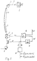
- a thread tension measuring instrument 8 is arranged, by means of which the thread tension, also called “thread tension”, is measured and passed on as an output signal. It should be noted that after the output delivery unit 9 there is a winding or an intermediate treatment by heating.
- the output signal of the thread tension meter 8, which represents the measured thread tension force, is converted into a long-term value LW by a filter 11.
- the long-term value LW is fed to a control device 12 together with a target value.
- the target value and the long-term value are compared with one another and converted into an adjustment variable VS.
- the adjusting variable VS adjusts an actuator 7, by means of which the twist transmission of the friction false twister 6 to the thread 1 is controlled.
- the conveying component of the friction force lying in the thread direction is also influenced.
- the output signal of the thread tension force meter 8 as well as the adjustment signal VS of an evaluation device 10 are given up.
- the adjustment signal VS represents the mean value of the thread tension.
- the evaluation device 10 delivers an evaluation of the current output signal, which represents the currently measured thread tension, in accordance with the principles described in EP 207 471 A1.
- an upper limit value and a lower limit value for the adjustment signal VS are stored in the evaluation device 10. If the adjustment signal VS exceeds one of these limit values, an alarm signal is issued, possibly an error message. Furthermore, the difference value DU between the current output signal and the adjustment signal VS - after both have previously been converted into compatible, comparable quantities - is formed in the evaluation device 10. Finally, the upper limit value and the lower limit value of this difference signal DU (GODU, GUDU) are stored in the evaluation device 10, and an alarm signal A occurs when the difference signal DU between the adjustment signal and the currently measured output signal exceeds one of the limit values GODU, GUDU.
- No. 92 100 490.9 (Bag. 1903) to determine the standard deviation of the thread tension.
- the thread tension is measured.
- the measured value is converted into an average value of the thread tension by a filter.
- the measurement signal and its continuously formed mean are subtracted and the difference squared.
- the standard deviation S is formed from this squared difference by root formation.
- the adjusting device 7 can, for. B. the drive motor of the friction false twister.
- the device 12 converts the difference signal from the long-term value and the setpoint into a manipulated variable, e.g. into a frequency that determines the speed of the drive motor 7 of the friction false twist designed as a synchronous motor or as an asynchronous motor.
- the adjusting device 7 can alternatively or additionally adjust the center distance, for example by the axes are each mounted on an eccentric and the eccentrics are rotated accordingly depending on the adjustment signal VS (cf. DE-AS 21 30 550).
- the friction false twister consists of two disks, which clamp the thread between them and of which an elastic disk is pressed against the other disk by a pressing device (see e.g. EP 22 743 A1)
- the contact pressure can be adjusted by the adjustment signal VS.
- the friction false twister consists of two belts that run endlessly transversely to the thread axis and pinch the thread between them (e.g. US 4,248,038), the belt bearings being adjusted relative to each other with a predeterminable force, this force can be adjusted by the adjustment signal VS.
- the friction force can be predetermined by a predetermined speed, since there is a connection between friction force and speed in the case of friction false twists.
- the speed can serve either as the sole manipulated variable or as an additional manipulated variable in addition to the measures already mentioned.
- the creation process is divided into times Z1 to Z4.
- the thread is drawn from the supply spool 2 by means of a feed gun from the supply spool and introduced into the feed unit 9, the friction false twister 6, the thread tension force meter 8.
- the adjustment device 7 of the friction false twister 6 is not set to normal operation, but rather to a constant value, e.g. is equal to or less than the operating setpoint.
- the thread tension meter 8 already shows a deflection, even if the delivery mechanism 3 is not yet activated. However, the thread path is very unstable. Therefore, the thread tension fluctuations, determined in the form of the CV value, are very high.
- Feeding time Z2 Now the thread that is still running in the suction gun is put on the heating rail 4 and the cooling rail 5. The feed mechanism 3 is closed, so that the thread is now exposed to an increased thread tension due to the clamping between the feed mechanisms 3 and 9 and their speed difference, as well as the increasing twist. However, the thread run becomes more stable, so that the standard deviation becomes smaller.
- Feed time Z3 the thread run has stabilized.
- the standard deviation falls below a predetermined limit.
- the application time Z3 is therefore a test time. During this test period it is recorded whether the limit value of the standard deviation is still exceeded. If the standard deviation does not exceed the limit value during the test time, the thread tension control is switched on after the test time has expired, in that the thread tension meter 8 and the adjustment device 7 of the friction false twister 6 are included in a control loop.
- the adjusting device by means of which the frictional force of the friction false twister 6 is predetermined, is adjusted in such a way that the thread tension meter 8 shows an essentially constant thread tension force.
- test period Z3 is restarted after it has expired.
- the Quality monitoring started.
- the thread tension is now monitored using the measures described above. It is thus monitored whether the thread tension or evaluation signals derived therefrom and / or the adjustment signal predetermined for the adjusting device 7 leave predetermined tolerance ranges. These events can be registered alone or as a whole for determining the quality of the coil produced.
- the quality monitoring is switched on after the end of a total creation time that is greater than the sum of the times Z1 - Z4 described above. This ensures that if the machine is set incorrectly or the machine fails, quality errors in the spool can be detected and eliminated.
- the means provided by the invention can be used to react immediately in the event of quality deviations due to exceptional operating situations in order to achieve the desired quality. Otherwise there is always the option of making a thread cut if the quality errors cannot be corrected.
Landscapes
- Engineering & Computer Science (AREA)
- Textile Engineering (AREA)
- Health & Medical Sciences (AREA)
- Life Sciences & Earth Sciences (AREA)
- Chemical & Material Sciences (AREA)
- Analytical Chemistry (AREA)
- Immunology (AREA)
- Physics & Mathematics (AREA)
- Food Science & Technology (AREA)
- Biochemistry (AREA)
- General Health & Medical Sciences (AREA)
- General Physics & Mathematics (AREA)
- Medicinal Chemistry (AREA)
- Pathology (AREA)
- Mechanical Engineering (AREA)
- Yarns And Mechanical Finishing Of Yarns Or Ropes (AREA)
- Filamentary Materials, Packages, And Safety Devices Therefor (AREA)
- Spinning Or Twisting Of Yarns (AREA)
- Tension Adjustment In Filamentary Materials (AREA)
Applications Claiming Priority (2)
| Application Number | Priority Date | Filing Date | Title |
|---|---|---|---|
| DE4203788 | 1992-02-10 | ||
| DE4203788 | 1992-02-10 |
Publications (3)
| Publication Number | Publication Date |
|---|---|
| EP0555639A2 true EP0555639A2 (fr) | 1993-08-18 |
| EP0555639A3 EP0555639A3 (fr) | 1993-09-01 |
| EP0555639B1 EP0555639B1 (fr) | 1995-04-05 |
Family
ID=6451310
Family Applications (1)
| Application Number | Title | Priority Date | Filing Date |
|---|---|---|---|
| EP93100364A Expired - Lifetime EP0555639B1 (fr) | 1992-02-10 | 1993-01-13 | Procédé pour le réglage de la force de tension des fils en mouvement sur une machine à texturer par fausse torsion |
Country Status (5)
| Country | Link |
|---|---|
| US (1) | US5369945A (fr) |
| EP (1) | EP0555639B1 (fr) |
| DE (1) | DE59300117D1 (fr) |
| RU (1) | RU2098525C1 (fr) |
| TW (1) | TW208049B (fr) |
Cited By (2)
| Publication number | Priority date | Publication date | Assignee | Title |
|---|---|---|---|---|
| WO1997038306A1 (fr) * | 1996-04-09 | 1997-10-16 | Temco Textilmaschinenkomponenten Gmbh & Co. Kg | Procede et dispositif pour detecter des sections de fil non texturees dans des fils continus |
| US6303938B1 (en) | 1996-04-09 | 2001-10-16 | Deutsche Institute Fur Textil-Und Faserforschung | Method and device for detection of untextured yarn sections in textured filament yarns |
Families Citing this family (4)
| Publication number | Priority date | Publication date | Assignee | Title |
|---|---|---|---|---|
| GB9202397D0 (en) * | 1992-02-05 | 1992-03-18 | British Tech Group | Texturing yarn |
| GB9315638D0 (en) * | 1993-07-28 | 1993-09-08 | Univ Manchester | False twist texturing |
| EP0751244B1 (fr) * | 1995-06-30 | 2007-08-08 | Oerlikon Textile GmbH & Co. KG | Procédé pour le réglage de la force de tension de fil |
| CN106647593A (zh) * | 2017-02-22 | 2017-05-10 | 苏州普力玛智能电子有限公司 | 一种假捻丝的质量监测方法及系统 |
Citations (3)
| Publication number | Priority date | Publication date | Assignee | Title |
|---|---|---|---|---|
| US4896407A (en) * | 1989-03-03 | 1990-01-30 | Milliken Research Corporation | Air pressure control for yarn texturing processes |
| US4961308A (en) * | 1987-09-03 | 1990-10-09 | Hans Stahlecker | Machine for pneumatic false-twist spinning |
| WO1992011535A1 (fr) * | 1990-12-19 | 1992-07-09 | Barmag Ag | Procede pour le reglage de la force de tension de fil |
Family Cites Families (9)
| Publication number | Priority date | Publication date | Assignee | Title |
|---|---|---|---|---|
| FR2115180B1 (fr) * | 1970-11-28 | 1974-06-07 | Schubert & Salzer Maschinen | |
| DE2155514B2 (de) * | 1971-11-09 | 1975-08-14 | Barmag Barmer Maschinenfabrik Ag, 5600 Wuppertal | Arbeitsverfahren zum Anlegen des Fadens an eine Streck- und Falschdrahtkräuselmaschine |
| US4015414A (en) * | 1974-06-12 | 1977-04-05 | The Warner & Swasey Textile Machine Company | Monitored twist control apparatus and method |
| JPS5545849A (en) * | 1978-09-27 | 1980-03-31 | Oda Gosen Kogyo Kk | False twisting method and apparatus |
| DE3066049D1 (en) * | 1979-07-14 | 1984-02-09 | Barmag Barmer Maschf | Apparatus for false-twisting yarns, and application of this apparatus to make a yarn |
| DE3306594A1 (de) * | 1982-05-21 | 1983-11-24 | Barmag Barmer Maschinenfabrik Ag, 5630 Remscheid | Verfahren zum falschzwirntexturieren |
| CN1027926C (zh) * | 1985-07-03 | 1995-03-15 | 巴马格巴默机器制造股份公司 | 运转纱线的连续监控方法 |
| US5146739A (en) * | 1990-01-26 | 1992-09-15 | Barmag Ag | Yarn false twist texturing process and apparatus |
| DE4138509A1 (de) * | 1991-01-21 | 1992-08-20 | Barmag Barmer Maschf | Kuehlvorrichtung fuer einen laufenden faden |
-
1993
- 1993-01-13 DE DE59300117T patent/DE59300117D1/de not_active Expired - Fee Related
- 1993-01-13 EP EP93100364A patent/EP0555639B1/fr not_active Expired - Lifetime
- 1993-02-09 RU RU9393004470A patent/RU2098525C1/ru active
- 1993-02-09 US US08/015,462 patent/US5369945A/en not_active Expired - Fee Related
- 1993-02-10 TW TW082100931A patent/TW208049B/zh active
Patent Citations (3)
| Publication number | Priority date | Publication date | Assignee | Title |
|---|---|---|---|---|
| US4961308A (en) * | 1987-09-03 | 1990-10-09 | Hans Stahlecker | Machine for pneumatic false-twist spinning |
| US4896407A (en) * | 1989-03-03 | 1990-01-30 | Milliken Research Corporation | Air pressure control for yarn texturing processes |
| WO1992011535A1 (fr) * | 1990-12-19 | 1992-07-09 | Barmag Ag | Procede pour le reglage de la force de tension de fil |
Cited By (2)
| Publication number | Priority date | Publication date | Assignee | Title |
|---|---|---|---|---|
| WO1997038306A1 (fr) * | 1996-04-09 | 1997-10-16 | Temco Textilmaschinenkomponenten Gmbh & Co. Kg | Procede et dispositif pour detecter des sections de fil non texturees dans des fils continus |
| US6303938B1 (en) | 1996-04-09 | 2001-10-16 | Deutsche Institute Fur Textil-Und Faserforschung | Method and device for detection of untextured yarn sections in textured filament yarns |
Also Published As
| Publication number | Publication date |
|---|---|
| TW208049B (fr) | 1993-06-21 |
| US5369945A (en) | 1994-12-06 |
| EP0555639A3 (fr) | 1993-09-01 |
| EP0555639B1 (fr) | 1995-04-05 |
| DE59300117D1 (de) | 1995-05-11 |
| RU2098525C1 (ru) | 1997-12-10 |
Similar Documents
| Publication | Publication Date | Title |
|---|---|---|
| EP2315864B1 (fr) | Procédé pour faire fonctionner une broche d'une machine à retordre à double torsion ou d'une machine de câblage | |
| DE2118775A1 (de) | Verfahren und Vorrichtung zum Antreiben einer offenendigen Spinnmaschine | |
| EP0296546A1 (fr) | Métier à filer pour la production de fils d'un ruban de fibres discontinues | |
| DE69405197T2 (de) | Methode zum Aufwickeln von Fäden | |
| EP3088576B1 (fr) | Procede de fonctionnement d'une broche d'une retordeuse a double fil ou a cable et retordeuse a double fil ou a cable | |
| EP0555639B1 (fr) | Procédé pour le réglage de la force de tension des fils en mouvement sur une machine à texturer par fausse torsion | |
| DE2313788A1 (de) | Verfahren zum selbsttaetigen anfahren und abstellen einer offen-end-spinnmaschine | |
| DE2255486C3 (de) | Fadenspeichervorrichtung | |
| EP2565306B1 (fr) | Métier à tisser à rotor à extrémité ouverte | |
| EP1550748A2 (fr) | Dispositif et procédure pour la fabrication de fils retors | |
| DE2812100C2 (de) | Verfahren zum Führen eines aus Einzelsträngen zusammengesetzten Gesamtstranges und Herstellen von gefachten Drahtspulen sowie Vorrichtung zum Durchführen des Verfahrens | |
| DE10037513B4 (de) | Verfahren zum Steuern einer Ringspinnmaschine und Spinnmaschine | |
| EP1521870B1 (fr) | Dispositif pour guider, traiter ou transporter au moins un fil | |
| DE3844671C2 (de) | Verfahren zum Einführen eines Faserbündels in eine laufriemenbetriebene Falschdrehvorrichtung | |
| DE102007038871A1 (de) | Verfahren zum Anspinnen an Textilmaschinen mit einer Mehrzahl von Spinnstellen | |
| EP2832904A1 (fr) | Métier à tisser et dispositif fausse-torsion | |
| EP1550749A2 (fr) | Disposifif pour réguler la tension de fil dans une broche à retordre, en particulier, dans une broche à retordre à double torsion | |
| DE960163C (de) | Verfahren zum Herstellen eines Zwirnes, insbesondere Cordzwirnes aus zwei Faeden | |
| EP3683342A1 (fr) | Procédé d'introduction de fausse torsion dans un fil et métier à filer ainsi que dispositif d'introduction de fausse torsion dans un fil | |
| DE2721972A1 (de) | Verfahren und vorrichtung zum aufwickeln von faeden | |
| DE2206577A1 (de) | Vorrichtung zum verstrecken, trennen und aufspulen von faeden | |
| EP0516786B1 (fr) | Procede pour le reglage de la force de tension de fil | |
| DE2918174A1 (de) | Verfahren und vorrichtung zum automatischen fadenanwickeln auf eine aufspuleinheit | |
| DE102014017674A1 (de) | Verfahren zum Betreiben einer Arbeitsstelle und Arbeitsstelle einer Doppeldrahtzwirn- oder Kabliermaschine | |
| WO2021105382A1 (fr) | Unité de filage et métier à filer à jet d'air comprenant une telle unité de filage |
Legal Events
| Date | Code | Title | Description |
|---|---|---|---|
| PUAI | Public reference made under article 153(3) epc to a published international application that has entered the european phase |
Free format text: ORIGINAL CODE: 0009012 |
|
| PUAL | Search report despatched |
Free format text: ORIGINAL CODE: 0009013 |
|
| AK | Designated contracting states |
Kind code of ref document: A2 Designated state(s): CH DE ES FR GB IT LI |
|
| AK | Designated contracting states |
Kind code of ref document: A3 Designated state(s): CH DE ES FR GB IT LI |
|
| 17P | Request for examination filed |
Effective date: 19930828 |
|
| 17Q | First examination report despatched |
Effective date: 19940704 |
|
| ITF | It: translation for a ep patent filed | ||
| GRAA | (expected) grant |
Free format text: ORIGINAL CODE: 0009210 |
|
| AK | Designated contracting states |
Kind code of ref document: B1 Designated state(s): CH DE ES FR GB IT LI |
|
| PG25 | Lapsed in a contracting state [announced via postgrant information from national office to epo] |
Ref country code: ES Free format text: THE PATENT HAS BEEN ANNULLED BY A DECISION OF A NATIONAL AUTHORITY Effective date: 19950405 |
|
| REF | Corresponds to: |
Ref document number: 59300117 Country of ref document: DE Date of ref document: 19950511 |
|
| GBT | Gb: translation of ep patent filed (gb section 77(6)(a)/1977) |
Effective date: 19950605 |
|
| ET | Fr: translation filed | ||
| PLBE | No opposition filed within time limit |
Free format text: ORIGINAL CODE: 0009261 |
|
| STAA | Information on the status of an ep patent application or granted ep patent |
Free format text: STATUS: NO OPPOSITION FILED WITHIN TIME LIMIT |
|
| 26N | No opposition filed | ||
| REG | Reference to a national code |
Ref country code: CH Ref legal event code: NV Representative=s name: BARMAG GMBH ENGINEERING & MANUFACTURING |
|
| PGFP | Annual fee paid to national office [announced via postgrant information from national office to epo] |
Ref country code: GB Payment date: 20001227 Year of fee payment: 9 |
|
| PGFP | Annual fee paid to national office [announced via postgrant information from national office to epo] |
Ref country code: FR Payment date: 20010118 Year of fee payment: 9 |
|
| PGFP | Annual fee paid to national office [announced via postgrant information from national office to epo] |
Ref country code: CH Payment date: 20010124 Year of fee payment: 9 |
|
| PGFP | Annual fee paid to national office [announced via postgrant information from national office to epo] |
Ref country code: DE Payment date: 20010219 Year of fee payment: 9 |
|
| REG | Reference to a national code |
Ref country code: GB Ref legal event code: IF02 |
|
| PG25 | Lapsed in a contracting state [announced via postgrant information from national office to epo] |
Ref country code: GB Free format text: LAPSE BECAUSE OF NON-PAYMENT OF DUE FEES Effective date: 20020113 |
|
| PG25 | Lapsed in a contracting state [announced via postgrant information from national office to epo] |
Ref country code: LI Free format text: LAPSE BECAUSE OF NON-PAYMENT OF DUE FEES Effective date: 20020131 Ref country code: CH Free format text: LAPSE BECAUSE OF NON-PAYMENT OF DUE FEES Effective date: 20020131 |
|
| PG25 | Lapsed in a contracting state [announced via postgrant information from national office to epo] |
Ref country code: DE Free format text: LAPSE BECAUSE OF NON-PAYMENT OF DUE FEES Effective date: 20020801 |
|
| GBPC | Gb: european patent ceased through non-payment of renewal fee |
Effective date: 20020113 |
|
| REG | Reference to a national code |
Ref country code: CH Ref legal event code: PL |
|
| PG25 | Lapsed in a contracting state [announced via postgrant information from national office to epo] |
Ref country code: FR Free format text: LAPSE BECAUSE OF NON-PAYMENT OF DUE FEES Effective date: 20020930 |
|
| REG | Reference to a national code |
Ref country code: FR Ref legal event code: ST |
|
| PG25 | Lapsed in a contracting state [announced via postgrant information from national office to epo] |
Ref country code: IT Free format text: LAPSE BECAUSE OF NON-PAYMENT OF DUE FEES;WARNING: LAPSES OF ITALIAN PATENTS WITH EFFECTIVE DATE BEFORE 2007 MAY HAVE OCCURRED AT ANY TIME BEFORE 2007. THE CORRECT EFFECTIVE DATE MAY BE DIFFERENT FROM THE ONE RECORDED. Effective date: 20050113 |