EP0553475B1 - Kaschiermaschine - Google Patents
Kaschiermaschine Download PDFInfo
- Publication number
- EP0553475B1 EP0553475B1 EP92121575A EP92121575A EP0553475B1 EP 0553475 B1 EP0553475 B1 EP 0553475B1 EP 92121575 A EP92121575 A EP 92121575A EP 92121575 A EP92121575 A EP 92121575A EP 0553475 B1 EP0553475 B1 EP 0553475B1
- Authority
- EP
- European Patent Office
- Prior art keywords
- laminator
- accordance
- roller
- film
- pressure
- Prior art date
- Legal status (The legal status is an assumption and is not a legal conclusion. Google has not performed a legal analysis and makes no representation as to the accuracy of the status listed.)
- Expired - Lifetime
Links
- 238000010030 laminating Methods 0.000 claims abstract description 5
- 238000005520 cutting process Methods 0.000 claims description 17
- 230000001681 protective effect Effects 0.000 claims description 16
- 229910052751 metal Inorganic materials 0.000 claims description 6
- 239000002184 metal Substances 0.000 claims description 6
- 238000010276 construction Methods 0.000 claims description 5
- 239000000463 material Substances 0.000 abstract description 4
- 239000000758 substrate Substances 0.000 abstract 2
- 241001131696 Eurystomus Species 0.000 description 15
- 238000003475 lamination Methods 0.000 description 9
- 238000000034 method Methods 0.000 description 5
- 230000008569 process Effects 0.000 description 4
- 230000002349 favourable effect Effects 0.000 description 3
- 238000010438 heat treatment Methods 0.000 description 3
- 230000005855 radiation Effects 0.000 description 3
- 239000002699 waste material Substances 0.000 description 3
- 239000011248 coating agent Substances 0.000 description 2
- 238000000576 coating method Methods 0.000 description 2
- 230000001419 dependent effect Effects 0.000 description 2
- 238000004519 manufacturing process Methods 0.000 description 2
- 239000000123 paper Substances 0.000 description 2
- 241001136792 Alle Species 0.000 description 1
- 241000283707 Capra Species 0.000 description 1
- 229920000049 Carbon (fiber) Polymers 0.000 description 1
- 229910000831 Steel Inorganic materials 0.000 description 1
- 238000005299 abrasion Methods 0.000 description 1
- 230000009471 action Effects 0.000 description 1
- 229910052782 aluminium Inorganic materials 0.000 description 1
- XAGFODPZIPBFFR-UHFFFAOYSA-N aluminium Chemical compound [Al] XAGFODPZIPBFFR-UHFFFAOYSA-N 0.000 description 1
- 230000008901 benefit Effects 0.000 description 1
- 230000015572 biosynthetic process Effects 0.000 description 1
- 239000004917 carbon fiber Substances 0.000 description 1
- 239000011111 cardboard Substances 0.000 description 1
- 239000012876 carrier material Substances 0.000 description 1
- 230000008859 change Effects 0.000 description 1
- 239000003086 colorant Substances 0.000 description 1
- 230000008878 coupling Effects 0.000 description 1
- 238000010168 coupling process Methods 0.000 description 1
- 238000005859 coupling reaction Methods 0.000 description 1
- 230000003670 easy-to-clean Effects 0.000 description 1
- 230000008030 elimination Effects 0.000 description 1
- 238000003379 elimination reaction Methods 0.000 description 1
- 239000011888 foil Substances 0.000 description 1
- 239000000976 ink Substances 0.000 description 1
- 238000007689 inspection Methods 0.000 description 1
- 239000002245 particle Substances 0.000 description 1
- 239000004033 plastic Substances 0.000 description 1
- -1 polytetrafluoroethylene Polymers 0.000 description 1
- 229920001343 polytetrafluoroethylene Polymers 0.000 description 1
- 239000004810 polytetrafluoroethylene Substances 0.000 description 1
- 230000036316 preload Effects 0.000 description 1
- 230000009467 reduction Effects 0.000 description 1
- 238000007788 roughening Methods 0.000 description 1
- 238000000926 separation method Methods 0.000 description 1
- 229920002379 silicone rubber Polymers 0.000 description 1
- 239000004945 silicone rubber Substances 0.000 description 1
- 239000010959 steel Substances 0.000 description 1
- 238000013517 stratification Methods 0.000 description 1
- 238000011144 upstream manufacturing Methods 0.000 description 1
Images

Classifications
-
- B—PERFORMING OPERATIONS; TRANSPORTING
- B32—LAYERED PRODUCTS
- B32B—LAYERED PRODUCTS, i.e. PRODUCTS BUILT-UP OF STRATA OF FLAT OR NON-FLAT, e.g. CELLULAR OR HONEYCOMB, FORM
- B32B37/00—Methods or apparatus for laminating, e.g. by curing or by ultrasonic bonding
- B32B37/14—Methods or apparatus for laminating, e.g. by curing or by ultrasonic bonding characterised by the properties of the layers
- B32B37/16—Methods or apparatus for laminating, e.g. by curing or by ultrasonic bonding characterised by the properties of the layers with all layers existing as coherent layers before laminating
- B32B37/22—Methods or apparatus for laminating, e.g. by curing or by ultrasonic bonding characterised by the properties of the layers with all layers existing as coherent layers before laminating involving the assembly of both discrete and continuous layers
- B32B37/223—One or more of the layers being plastic
- B32B37/226—Laminating sheets, panels or inserts between two continuous plastic layers
-
- B—PERFORMING OPERATIONS; TRANSPORTING
- B32—LAYERED PRODUCTS
- B32B—LAYERED PRODUCTS, i.e. PRODUCTS BUILT-UP OF STRATA OF FLAT OR NON-FLAT, e.g. CELLULAR OR HONEYCOMB, FORM
- B32B37/00—Methods or apparatus for laminating, e.g. by curing or by ultrasonic bonding
- B32B37/0046—Methods or apparatus for laminating, e.g. by curing or by ultrasonic bonding characterised by constructional aspects of the apparatus
- B32B37/0053—Constructional details of laminating machines comprising rollers; Constructional features of the rollers
-
- B—PERFORMING OPERATIONS; TRANSPORTING
- B32—LAYERED PRODUCTS
- B32B—LAYERED PRODUCTS, i.e. PRODUCTS BUILT-UP OF STRATA OF FLAT OR NON-FLAT, e.g. CELLULAR OR HONEYCOMB, FORM
- B32B37/00—Methods or apparatus for laminating, e.g. by curing or by ultrasonic bonding
- B32B37/10—Methods or apparatus for laminating, e.g. by curing or by ultrasonic bonding characterised by the pressing technique, e.g. using action of vacuum or fluid pressure
- B32B37/1045—Intermittent pressing, e.g. by oscillating or reciprocating motion of the pressing means
-
- B—PERFORMING OPERATIONS; TRANSPORTING
- B32—LAYERED PRODUCTS
- B32B—LAYERED PRODUCTS, i.e. PRODUCTS BUILT-UP OF STRATA OF FLAT OR NON-FLAT, e.g. CELLULAR OR HONEYCOMB, FORM
- B32B38/00—Ancillary operations in connection with laminating processes
- B32B38/18—Handling of layers or the laminate
- B32B38/1825—Handling of layers or the laminate characterised by the control or constructional features of devices for tensioning, stretching or registration
- B32B38/1833—Positioning, e.g. registration or centering
- B32B38/1841—Positioning, e.g. registration or centering during laying up
- B32B38/185—Positioning, e.g. registration or centering during laying up combined with the cutting of one or more layers
-
- B—PERFORMING OPERATIONS; TRANSPORTING
- B32—LAYERED PRODUCTS
- B32B—LAYERED PRODUCTS, i.e. PRODUCTS BUILT-UP OF STRATA OF FLAT OR NON-FLAT, e.g. CELLULAR OR HONEYCOMB, FORM
- B32B38/00—Ancillary operations in connection with laminating processes
- B32B38/18—Handling of layers or the laminate
- B32B38/1866—Handling of layers or the laminate conforming the layers or laminate to a convex or concave profile
-
- B—PERFORMING OPERATIONS; TRANSPORTING
- B32—LAYERED PRODUCTS
- B32B—LAYERED PRODUCTS, i.e. PRODUCTS BUILT-UP OF STRATA OF FLAT OR NON-FLAT, e.g. CELLULAR OR HONEYCOMB, FORM
- B32B38/00—Ancillary operations in connection with laminating processes
- B32B38/16—Drying; Softening; Cleaning
- B32B38/162—Cleaning
-
- Y—GENERAL TAGGING OF NEW TECHNOLOGICAL DEVELOPMENTS; GENERAL TAGGING OF CROSS-SECTIONAL TECHNOLOGIES SPANNING OVER SEVERAL SECTIONS OF THE IPC; TECHNICAL SUBJECTS COVERED BY FORMER USPC CROSS-REFERENCE ART COLLECTIONS [XRACs] AND DIGESTS
- Y10—TECHNICAL SUBJECTS COVERED BY FORMER USPC
- Y10T—TECHNICAL SUBJECTS COVERED BY FORMER US CLASSIFICATION
- Y10T156/00—Adhesive bonding and miscellaneous chemical manufacture
- Y10T156/17—Surface bonding means and/or assemblymeans with work feeding or handling means
- Y10T156/1702—For plural parts or plural areas of single part
- Y10T156/1712—Indefinite or running length work
- Y10T156/1741—Progressive continuous bonding press [e.g., roll couples]
Definitions
- the invention relates to a laminator for laminating a film on a support, with a between a stationary base roller and one upper pressure roller formed upper nip, the the carrier over an entry plate and a film of an upper supply roll after removing a protective film can be fed, the upper pressure roller by means of a switching device from a rest position, in which the upper press nip is open, in a working position, in which the upper press nip is closed and the roller drive is switched on and back is adjustable.
- Such a laminator is for example under the name "CROMALIN-Laminator 2700" (registered trade mark) known to the applicant. It is used in connection with a color inspection system used. After exposure of the laminate, which consists of a sheet-like support and a light-sensitive film there are sticky areas where - after Peeling off a top layer - toner sticks. After After lamination, the film is opened on the output side cut off a cutting plate. The subsequent one Filmbahn therefore remains with its initial section in the open nip where they are for the next lamination process is available.
- CROMALIN-Laminator 2700 registered trade mark
- the invention has for its object a laminator of the type described in the introduction, to simple way of coating a particular one leaf-shaped carrier with two different Enables filming.
- the base roller with a lower pressure roller forms the lower press nip, which the carrier via an inlet plate alternatively to the upper press nip and a second film from a lower supply roll after removal a protective film can be fed and that lower pressure roller by means of a switching device from a rest position, in which the lower press nip is open, in a working position in which the lower one Press nip closed and the roller drive in the opposite Direction is on, and back is adjustable.
- the user can carry the carrier either on the top or on the bottom with provided a film. All it takes is one or the other the other nip to be made effective to the Laminate supports with different film material. Because of the presence of two press nips can the unused film remains in the press nip, so that he is ready for the next lamination process right place. Space requirements and costs are significantly less than when using two Laminators. An exchange of the supply rolls is only required after complete consumption.
- the laminator is suitable for a wide variety of applications, where two different films must be applied. Even with photosensitive There are several types of films (as positive film and as Negative film), several qualities (e.g. regarding the Resolution) and various widths. It exists also the possibility for aesthetic reasons to laminate different colored foils on a carrier. Lamination can be done in a cold condition or be supported by heating.
- the base roller is driven and the two pressure rollers are heated.
- the functions of the drive and the heating separately, which simplifies construction brings with it.
- the heat is also applied through the film. It can therefore be optimal can be adjusted and does not depend on the thickness of the carrier material dependent.
- the two pressure rollers are stored in common side panels that are pivotable about a fixed axis.
- the side parts are outside the lamination work area and can also take on other functions.
- the switching device has a pivot axis has, which by means of a lever around a predetermined Angle is rotatable and carries two eccentric discs, and that the side parts are two opposite each other Have support devices on the eccentric discs attack.
- the lever makes it easy Way, the two side parts and thus that of parts carried to them in one of two working positions or to put it in a rest position.
- Each support device advantageously has a prestressed one Spring on between the eccentric and Side part is effective. This will in the end positions the side parts a predetermined pressure between Pressure roller and base roller achieved. Conveniently the preload is adjustable to achieve the desired lamination result to achieve.
- a common inlet plate section is advantageous provided that together with the pressure rollers is adjustable so that it is closed on each Press nip has. This is space-saving and easier the company.
- the common inlet plate section pivotable about a fixed pivot axis and via a driver from the swiveling side parts be adjustable.
- each press nip on the output side a film clamping device is assigned. With this you can the films not used in one position are kept tense in which they are neither driven by the Base roller are still taken away by the heated pressure roller an excessive temperature load Experienced.
- each press nip on the output side a stationary insert is assigned to the carries a cutting surface on the top. The operator can therefore after each pass of the carrier cut the film off comfortably. This allows the Waste of footage should be kept to a minimum.
- the upper insert can be swiveled and with a clamping section against a fixed one upper terminal strip can be put on and a lower terminal strip pivotable and against a clamping section of the fixed lower insert can be applied.
- the clamping section or the terminal block should have an elastic pad. This results in secure clamping even with different thicknesses Film.
- the switching device has a particular advantage a pivot axis, the eccentric for pivoting the upper insert and lever to hold the lower one Terminal strip carries.
- the clamps are therefore automatically when the switching device is actuated served.
- the pivot axis be the same as the side parts over eccentric washers adjusted.
- a upper guide device and a lower guide device which are upstream of the press nips in the path of the film and each consist of two guide rollers, one of which stationary and the other stored in the side panels is.
- the two guide rollers are in the working position to each other and enable a safe separation between film and protective film. Are at rest the guide rollers separated from each other so that the film no pressure point or the like receives.
- the device for braking and tensioning have a braking element that frictionally the supply roll works, is loaded by a spring, under the influence of peeling the film by a limited amount Angle swiveling and under the influence of Spring is pivotable back through the limited angle.
- a braking element that frictionally the supply roll works, is loaded by a spring, under the influence of peeling the film by a limited amount Angle swiveling and under the influence of Spring is pivotable back through the limited angle.
- a sensor device is also very useful End of the incoming carrier detected and dependent of which the roller drive with a time delay switches off.
- the time delay is chosen so that the Drive motor automatically turns off when the carrier has left the press nip and due to its inertia with its rear edge in the area of the associated Insert is lying.
- the base roller has a metal core and is provided with a non-stick layer.
- This non-stick layer ensures that even very thin supports, for example with a weight of 80 to 120 g / m 2 , leave the press nip safely and are not taken along by the base roller.
- an elastic layer may be provided between the metal core and the non-stick layer.
- the pressure rollers are expedient also provided with an elastic layer.
- the diameter of the base roller advantageously increases Ends towards.
- a slight concave shape, for example a constriction of 0.03 to 0.05 mm improves the uniform pressure in the nip over the length of the roller.
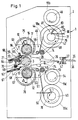
- a machine frame 1 has two spaced apart Side walls 2, in which a base roller 3 is mounted is. It is from a motor 4 via a belt drive 5 and a pulley 6 can be driven. She has a metal core 7 made of aluminum and / or Steel, directly or with the interposition of one elastic layer 8 applied a non-stick layer 9 is. This can in particular be made of polytetrafluoroethylene consist. This material is abrasion resistant and easy to clean and allows roughening appropriate friction drag of the carrier. Especially this layer can be applied as a shrink tube will. This can have a thickness of approximately, for example Have 0.3 mm. The optimal surface of the base roller 3 should be drawn in a little bit towards the middle, where one Diameter reduction from 0.03 to 0.05 mm favorable is.
- the base roller 3 forms together with an upper pressure roller 10 an upper press nip 11 and together with a lower pressure roller 12 a nip 13.
- the two pressure rollers are mounted in side parts 14, which on both sides outside the side walls 2 arranged and pivotable about an axis 15. Out the illustrated intermediate or middle position can by swiveling the side parts 14 of the upper Press nip 11 or the lower press nip 13 closed will.
- the pressure rollers also have a metallic one Core 16. This is with an elastic Layer 17, for example made of silicone rubber, provided.
- the pressure rollers are through a heat transfer medium heatable, which is indicated by a supply line 18 or 19 is.
- the side parts 14 are parts of a switching device 20, which also includes a pivot axis 21, which with Help of a lever 22 attached to it after both Pages is rotatable through predetermined angles.
- the pivot axis 21 is two in the region of the side parts 14 circular eccentric 23 attached with Help of locking devices, of which the locking device 24 for the middle position is illustrated in three predetermined angular positions can be locked can.
- On opposite sides of the eccentric discs 23 engage two support devices 25 and 26, which are structured as follows: In an on the side part 14 attached housing 27 is a preloaded Spring 28 arranged on an adjusting screw 29 supports.
- the spring 28 acts via a Tappet 30 on a lever 31 which is about an axis 32 is pivotable on the side part 14 and by means of a ball 33 abuts the eccentric disk 23. In this way it is ensured that the respective pressure roller with a spring 28 determined Force applied to the base roller 3. Furthermore two springs 34 extend between the machine frame 1 and the side parts 14. They compensate at least part of the weight of the side parts 14 and the components they support. The contact conditions are therefore similar in the lower press nip 13 as in the upper press nip 11.
- Sheet-shaped carrier 35 made of paper, cardboard, plastic or the like and especially from very thin paper can exist, an inlet table 36 one antistatic device consisting of two brush units 37 fed. Every brush unit has Metal or carbon fibers for the elimination of electrical Charges and goat's eyes or the like. to strip off Dirt particles.
- a run-in plate section 38 can from the illustrated middle position to the the upper or lower dashed position can be pivoted, so that the respective carrier 35 either via an inlet plate 39 the upper press nip 11 or via a lower inlet plate 40 fed to the lower press nip 13 becomes.
- the inlet plate section 38 pivotable about an axis 41 fixed to the housing. He is also on pin-shaped drivers 42 to the Supported side parts 14. This way pivots the inlet plate section 38 when closing the upper one Press nip 11 upwards and when closing the lower press nip 13 down.
- a layered web 44 is drawn off, that in the area of a guide device 45 in a film 46 and a protective film 47 which is divided on a take-up roll 48 is collected. More like that There is a supply roll 49 for a lower layered Lane 50 in the area of a guide device 51 divided into a film 52 and a protective film 53 is collected on a take-up reel 54 becomes.
- the supply rolls 43 and 49 are drawn off by the Film shot. They take over a friction wheel clutch with the friction wheels 55a, 55b and 55c, 55d Take-up rolls 48 and 54 with.
- Any guidance device consists of a guide roller 56 or 56 ', which firmly the side walls 2 is mounted, and a second Guide roller 57 or 57 ', which is mounted in the side parts 14 and is provided with an elastic layer 58.
- active guide device 45 or 51 the guide roller 57 or 57 'pressed against the guide roller 56 or 56', which makes it easier to separate film and protective film becomes an unwanted one during the rest periods Press point is created.
- a cutting plate 59 provided a cutting surface at the top 60 owns.
- the lower press nip 13 is a cutting plate 61 downstream, which is an upper cutting surface 62 owns.
- the upper insert 59 is part of a Film clamp 63. For this purpose it is over a fixed axis 64 pivotable and can with a Clamping section 65 against a fixed upper terminal block be created.
- the lower insert 61 is arranged stationary and has to form a film clamping device 67 a clamping section 68 against which a terminal block 69 can be applied. This is on two Levers 70 attached, which of the pivot axis 21st be worn. Also sit on this swivel axis Eccentric 71, which the cutting plate 59 by means of a Swivel U-shaped driver.
- Terminal block 66 and the clamping section 69 each carry an elastic Edition.
- switches 72 and 73 which are actuated when that Side part 14 reaches the respective end position.
- Switch actuation the motor 4 in each correct direction of rotation and can then by turned on a foot switch, not shown will.
- a sensor 74 on the inlet plate section 38 in particular a photoelectric sensor is determined, when the rear edge of the carrier 35 passes over it and switches the motor 4 according to a predetermined one time delay. This time delay is dimensioned so that the carrier with its rear edge about in the area of the cutting surface 60 or 62 to rest is coming.
- Heat shields 75 and 76 protect the interior and the film supply rolls before the heat radiation of the Pressure rollers 10 and 12.
- Fig. 1 is a braking and tensioning device schematically 77 for the supply roll 43 and a brake and Tensioning device 78 for the supply roll 49 illustrated.
- the device 77 has a disc-shaped Brake element 79, the friction with the supply roll 43 cooperates.
- the braking element is under the action of a spring 80 and is between two fixed stops 81 and 82, between which one stop 83 movable with the braking element, pivotable through a limited angle. If a movie turns 46 Subtracted from the supply roll 43, the braking element pivots up to the stop 81. If the press nip 11 opened, the braking element 79 returns under the influence the spring 80 back to the illustrated rest position, at the same time the film is excited and from the Base roller 3 is lifted off.
- the braking and tensioning device 78 has a similar structure.
- Fig. 4 The constructive solution to such a device is illustrated in Fig. 4.
- the axis 84 of the supply roll is connected to a hub 85 via a coupling, which carries a thrust washer 86 on the outside. This is against the by an adjustable disc spring 87 Friction lining 88 of the disc-shaped brake element 79 pressed. This is about the limited angle around that Hub 85 swiveling.
- the spring engages with a pin 89 80 at the other end on a pin 90 on the Side wall 2 is attached.
- a carrier 35 is through the Antistatic device 37 via the upper inlet plate 39 fed to the press nip 11, in which he with the Film 46 is laminated.
- the sensor 74 Once the trailing edge of the carrier 35 reaches the sensor 74, there this emits a signal that after a certain time the Shutdown of the motor 4 causes.
- the rear edge is now in the area of the cutting surface 60 so that the operator can easily cut the film. All Rotational movements of this laminating process are pulled out Arrows indicated.
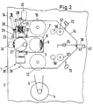
- the laminator can be returned to the middle position are returned, as shown in FIG. 1 and Figure 2 is illustrated. If the lever is pivoted further, the lower press nip closes 13. Simultaneously the inlet plate section 38 is pivoted downward. The guide rollers 56 ', 57' of the guide device 51 are pressed together. Finally the Switch 73 actuated. Now a carrier 35 can the inlet plate section 38 to the lower press nip 13 be fed where it is on its underside with a Film 52 is laminated while the protective film 53 is on the take-up roll 54 is collected.
- film 46 is photosensitive Film and film 52 a protective film.
- the wearer can print four colors in succession laminated with four photosensitive films, which are each colored with one of the printing inks, while in a last run a protective film is placed over these four photosensitive films.
- photosensitive films are those Films that are not actinic when exposed Radiation their stickiness e.g. through photopolymerization or lose photocrosslinking. Such films will be e.g. in the processes for the production of multi-color proofs according to US 4,356,253 and EP 0 243 933. But also photosensitive films that are used in the Exposure to actinic radiation can become sticky, such as they e.g. in U.S. 4,243,741 and U.S. 4,346,162 are for the production of multicolor proof prints suitable with the laminator according to the invention.
- protective films z. B. those in European Patent application EP-A-0 285 039 used films described be that an annoying shiny surface prevent.
Landscapes
- Physics & Mathematics (AREA)
- Fluid Mechanics (AREA)
- Lining Or Joining Of Plastics Or The Like (AREA)
- Laminated Bodies (AREA)
- Separation, Sorting, Adjustment, Or Bending Of Sheets To Be Conveyed (AREA)
- Manufacturing Of Printed Circuit Boards (AREA)
- Diaphragms For Electromechanical Transducers (AREA)
- Soil Working Implements (AREA)
Description
- Fig. 1
- einen schematischen Vertikalschnitt durch einen erfindungsgemäßen Laminator,
- Fig. 2
- schematisch und in vergrößerter Darstellung eine Außenansicht des Laminators,
- Fig. 3
- einen Teilquerschnitt längs der Linie A-A in Fig. 1 und
- Fig. 4
- einen Schnitt durch die Brems- und Spannvorrichtung.
Claims (23)
- Laminator zum Laminieren eines Films auf einen Träger, mit einem zwischen einer ortsfest gelagerten Basiswalze und einer oberen Andruckwalze gebildeten oberen Preßspalt, dem der Träger über eine Einlaufplatte sowie ein Film von einer oberen Vorratsrolle nach Entfernung einer Schutzfolie zuführbar ist, wobei die obere Andruckwalze mittels einer Umschaltvorrichtung aus einer Ruhestellung, in der der obere Preßspalt geöffnet ist, in eine Arbeitsstellung, in der der obere Preßspalt geschlossen und der Walzenantrieb eingeschaltet ist, und zurück verstellbar ist, wobei die Basiswalze (3) mit einer unteren Andruckwalze (12) einen unteren Preßspalt (13) bildet, dem der Träger (35) über eine Einlaufplatte (40) alternativ zum oberen Preßspalt (11) und ein zweiter Film (52) von einer unteren Vorratsrolle (49) nach Entfernung einer Schutzfolie (53) zuführbar ist, und wobei die untere Andruckwalze (12) mittels einer Umschaltvorrichtung (20) aus einer Ruhestellung, in der der untere Preßspalt (13) geöffnet ist, in eine Arbeitsstellung, in der der untere Preßspalt geschlossen und der Walzenantrieb in entgegengesetzte Richtung eingeschaltet ist, und zurück verstellbar ist.
- Laminator nach Anspruch 1, dadurch gekennzeichnet, daß die Basiswalze (3) angetrieben ist und die beiden Andruckwalzen (10, 12) beheizbar sind.
- Laminator nach Anspruch 1 oder 2, gekennzeichnet durch eine gemeinsame Umschaltvorrichtung (20), in deren Endlagen jeweils die eine Andruckwalze (10, 12) die Arbeitsstellung und die andere Andruckwalze die Ruhestellung einnimmt, während in einer Zwischenstellung beide Andruckwalzen von der Basiswalze (3) abgehoben sind.
- Laminator nach Anspruch 3, dadurch gekennzeichnet, daß die beiden Andruckwalzen (10, 12) in gemeinsamen Seitenteilen (14) gelagert sind, die um eine ortsfeste Achse (15) schwenkbar sind.
- Laminator nach Anspruch 4, dadurch gekennzeichnet, daß die Umschaltvorrichtung (20) eine Schwenkachse (21) aufweist, die mittels eines Hebels (22) um einen vorbestimmten Winkel drehbar ist und zwei Exzenterscheiben (23) trägt, und daß die Seitenteile (14) je zwei einander gegenüberliegende Stützvorrichtungen (25, 26) aufweisen, die an den Exzenterscheiben angreifen.
- Laminator nach Anspruch 5, dadurch gekennzeichnet, daß jede Stützvorrichtung (25, 26) eine vorgespannte Feder (28) aufweist, die zwischen Exzenterscheibe (23) und Seitenteil (14) wirksam ist.
- Laminator nach einem der Ansprüche 4 bis 6, dadurch gekennzeichnet, daß an den Seitenteilen (14) je eine Feder (34) angreift, die das Gewicht der Seitenteile und der von ihnen getragenen Bauelemente zumindest teilweise kompensiert.
- Laminator nach einem der Ansprüche 1 bis 7, dadurch gekennzeichnet, daß ein gemeinsamer Einlaufplattenabschnitt (38) vorgesehen ist, der zusammen mit den Andruckwalzen (10, 12) derart verstellbar ist, daß er auf den jeweils geschlossenen Preßspalt (11, 13) weist.
- Laminator nach Anspruch 4 und 8, dadurch gekennzeichnet, daß der gemeinsame Einlaufplattenabschnitt (38) um eine ortsfeste Schwenkachse (41) schwenkbar und über einen Mitnehmer (42) von den schwenkbaren Seitenteilen (14) verstellbar ist.
- Laminator nach Anspruch 9, dadurch gekennzeichnet, daß die Schwenkachse (41) des Einlaufplattenabschnitts (38), dessen Gelenk (42), die Schwenkachse (15) der Seitenteile (14) und die Achse der Basiswalze (3) in Durchlaufrichtung hintereinander angeordnet sind.
- Laminator nach einem der Ansprüche 1 bis 10, dadurch gekennzeichnet, daß jedem Preßspalt (11, 13) ausgangsseitig eine Filmklemmvorrichtung (63, 67) zugeordnet ist.
- Laminator nach einem der Ansprüche 1 bis 11, dadurch gekennzeichnet, daß jedem Preßspalt (11, 13) ausgangsseitig eine Schneidplatte (59, 61) zugeordnet ist, die an der Oberseite eine Schneidfläche (60, 62) trägt.
- Laminator nach Anspruch 11 und 12, dadurch gekennzeichnet, daß zur Bildung der Filmklemmvorrichtungen (63, 67) die obere Schneidplatte (59) schwenkbar und mit einem Klemmabschnitt (65) gegen eine feststehende obere Klemmleiste (66) anlegbar ist und eine untere Klemmleiste (69) schwenkbar und gegen einen Klemmabschnitt (68) der feststehenden unteren Schneidplatte (61) anlegbar ist.
- Laminator nach Anspruch 13, dadurch gekennzeichnet, daß der Klemmabschnitt (68) bzw. die Klemmleiste (66) eine elastische Auflage besitzt.
- Laminator nach einem der Ansprüche 11 bis 14, dadurch gekennzeichnet, daß die Umschaltvorrichtung (20) eine Schwenkachse (21) aufweist, die Exzenter (71) zum Verschwenken der oberen Schneidplatte (59) und Hebel (70) zum Halten der unteren Klemmleiste (69) trägt.
- Laminator nach einem der Ansprüche 4 bis 15, gekennzeichnet durch eine obere Leitvorrichtung (45) und eine untere Leitvorrichtung (51), die den Preßspalten (11, 13) im Weg des Films (46, 52) vorgeschaltet sind und je aus zwei Leitwalzen (56, 56', 57, 57') bestehen, von denen die eine ortsfest und die andere in den Seitenteilen (14) gelagert ist.
- Laminator nach einem der Ansprüche 1 bis 16, dadurch gekennzeichnet, daß beide Vorratsrollen (43, 49) je mit einer Vorrichtung (77, 78) zum Bremsen und Spannen des Films versehen sind.
- Laminator nach Anspruch 17, dadurch gekennzeichnet, daß die Vorrichtung (77, 78) zum Bremsen und Spannen ein Bremselement (79) aufweisen, das reibschlüssig auf die Vorratsrolle (43) wirkt, durch eine Feder belastet (80) ist, unter dem Einfluß des Abziehens des Films (46) um einen begrenzten Winkel schwenkbar und unter dem Einfluß der Feder um den begrenzten Winkel zurück schwenkbar ist.
- Laminator nach einem der Ansprüche 4 bis 18, dadurch gekennzeichnet, daß Schalter (72, 73) zur Freigabe des Walzenantriebs im Seitenteil-Schwenkweg angeordnet und vom Seitenteil (14) jeweils in einer seiner Endlagen betätigbar sind.
- Laminator nach einem der Ansprüche 1 bis 19, gekennzeichnet durch eine Sensorvorrichtung (74), die das Ende des einlaufenden Trägers (35) detektiert und in Abhängigkeit hiervon den Walzenantrieb mit Zeitverzögerung abschaltet.
- Laminator nach einem der Ansprüche 1 bis 20, dadurch gekennzeichnet, daß die Basiswalze (3) einen Metallkern (7) besitzt und mit einer Antihaftschicht (9) versehen ist.
- Laminator nach Anspruch 21, dadurch gekennzeichnet, daß zwischen Metallkern (7) und Antihaftschicht (9) eine elastische Schicht (8) vorgesehen ist.
- Laminator nach Anspruch 21 oder 22, dadurch gekennzeichnet, daß der Durchmesser der Basiswalze (3) zu den Enden hin zunimmt.
Applications Claiming Priority (2)
| Application Number | Priority Date | Filing Date | Title |
|---|---|---|---|
| DE4202553 | 1992-01-30 | ||
| DE4202553A DE4202553C2 (de) | 1992-01-30 | 1992-01-30 | Laminator |
Publications (2)
| Publication Number | Publication Date |
|---|---|
| EP0553475A1 EP0553475A1 (de) | 1993-08-04 |
| EP0553475B1 true EP0553475B1 (de) | 1998-04-22 |
Family
ID=6450562
Family Applications (1)
| Application Number | Title | Priority Date | Filing Date |
|---|---|---|---|
| EP92121575A Expired - Lifetime EP0553475B1 (de) | 1992-01-30 | 1992-12-18 | Kaschiermaschine |
Country Status (5)
| Country | Link |
|---|---|
| US (1) | US5356507A (de) |
| EP (1) | EP0553475B1 (de) |
| JP (1) | JP3305390B2 (de) |
| AT (1) | ATE165275T1 (de) |
| DE (2) | DE4202553C2 (de) |
Families Citing this family (19)
| Publication number | Priority date | Publication date | Assignee | Title |
|---|---|---|---|---|
| DE4114313C2 (de) * | 1991-05-02 | 1994-12-08 | Du Pont Deutschland | Laminator |
| US5735997A (en) * | 1993-06-21 | 1998-04-07 | Reinders; Johannes Antonius Maria | Device for mounting, laminating and/or enclosing an illustration, and a cassette for such a device |
| US5601685A (en) * | 1994-05-10 | 1997-02-11 | Polaroid Corporation | Laminator and loading system therefor |
| NL1000123C2 (nl) * | 1995-04-11 | 1996-10-14 | Sallmetall Bv | Inrichting voor het aan elkaar hechten van ten minste twee lagen. |
| US5728252A (en) * | 1995-09-19 | 1998-03-17 | Polaroid Corporation | Method and apparatus for laminating image-bearing media |
| US6059003A (en) * | 1998-07-29 | 2000-05-09 | Integrated Design Corporation | Web heating and pressing apparatus |
| US6213183B1 (en) | 1998-08-13 | 2001-04-10 | Eastman Kodak Company | Laminator assembly having an endless belt |
| US6463981B1 (en) | 1998-08-13 | 2002-10-15 | Eastman Kodak Company | Laminator assembly having a pressure roller with a deformable layer |
| US6994142B2 (en) * | 2004-05-10 | 2006-02-07 | Murphy Willis A | Laminating machine |
| JP2007008007A (ja) * | 2005-06-30 | 2007-01-18 | Noritsu Koki Co Ltd | ラミネート装置 |
| US20070029437A1 (en) * | 2005-08-05 | 2007-02-08 | General Binding Corporation | Film loading arrangement for laminator |
| DE112006002076B4 (de) * | 2005-08-05 | 2012-12-13 | General Binding Corp. | Filmladende Anordnung für Laminiergerät |
| US9925817B2 (en) * | 2011-06-09 | 2018-03-27 | Kabushiki Kaisha Toshiba | Decolorizing apparatus |
| DE202011052223U1 (de) * | 2011-12-07 | 2012-12-19 | Monolith GmbH Bürosysteme | Laminiergerät |
| CN105150665A (zh) * | 2015-08-26 | 2015-12-16 | 广德施可达岩棉制造有限公司 | 一种岩棉板的贴膜机 |
| KR102595928B1 (ko) * | 2018-09-28 | 2023-10-31 | 삼성디스플레이 주식회사 | 라미네이션용 롤러, 이를 포함하는 라미네이션 장치, 및 표시 장치의 라미네이션 방법 |
| US10953646B2 (en) | 2018-10-26 | 2021-03-23 | ACCO Brands Corporation | Laminating system with coded film cartridge |
| US20240359448A1 (en) * | 2021-07-27 | 2024-10-31 | Zuiko Corporation | Manufacturing device and manufacturing method for elastic laminate |
| CN119283386B (zh) * | 2024-11-11 | 2025-06-06 | 泰州新亿恒制药机械技术有限公司 | 一种带有自动裁剪的覆膜机 |
Family Cites Families (21)
| Publication number | Priority date | Publication date | Assignee | Title |
|---|---|---|---|---|
| US3623933A (en) * | 1966-07-05 | 1971-11-30 | Gen Binding Corp | Laminator |
| US3547730A (en) * | 1966-12-16 | 1970-12-15 | Du Pont | Machine for making resist images |
| US3901758A (en) * | 1973-05-14 | 1975-08-26 | Seal | Laminating apparatus utilizing offset rollers |
| US4025380A (en) * | 1975-07-24 | 1977-05-24 | International Business Machines Corporation | Variable resist laminator |
| US4151900A (en) * | 1977-11-30 | 1979-05-01 | Union Carbide Corporation | Brake assembly for a rotatable shaft |
| DE2758209C3 (de) * | 1977-12-27 | 1980-07-10 | Du Pont De Nemours (Deutschland) Gmbh, 4000 Duesseldorf | Lichtempfindliches Aufzeichnungsmaterial |
| DE3023247C2 (de) * | 1980-06-21 | 1982-09-02 | Du Pont de Nemours (Deutschland) GmbH, 4000 Düsseldorf | Lichtempfindliches Aufzeichnungsmaterial |
| US4356253A (en) * | 1980-12-12 | 1982-10-26 | E. I. Du Pont De Nemours And Company | Photoimaging process for forming multicolor images |
| JPS6071229A (ja) * | 1983-09-29 | 1985-04-23 | Somar Corp | オ−トラミネ−タ |
| DE3503715A1 (de) * | 1985-02-04 | 1986-08-07 | Somar Corp., Tokio/Tokyo | Automatischer laminator |
| JPS62214945A (ja) * | 1986-03-17 | 1987-09-21 | 株式会社イソワ | 片面段ボ−ル製造装置 |
| US4892802A (en) * | 1986-04-30 | 1990-01-09 | E. I. Du Pont De Nemours And Company | Positive working tonable film having a photohardenable layer |
| US4948704A (en) * | 1986-04-30 | 1990-08-14 | E. I. Du Pont De Nemours And Company | Process of forming imaged photohardened material |
| CA1317811C (en) * | 1986-04-30 | 1993-05-18 | Richard Douglas Bauer | Photohardenable mixture |
| DE3631803A1 (de) * | 1986-09-18 | 1988-03-31 | Bhs Bayerische Berg | Einseitige wellpappenmaschine |
| CA1306565C (en) * | 1987-03-30 | 1992-08-18 | Harvey Walter Taylor Jr. | Lower gloss protective covering |
| US4921776A (en) * | 1987-03-30 | 1990-05-01 | E. I. Du Pont De Nemours And Company | Method of providing lower gloss protective covering for pre-press color proof |
| US4971893A (en) * | 1987-03-30 | 1990-11-20 | E. I. Du Pont De Nemours And Company | Element containing lower gloss protective covering and a pre-press color proof |
| US5019536A (en) * | 1987-03-30 | 1991-05-28 | E. I. Du Pont De Nemours And Company | Lower gloss protective covering |
| DE3737946A1 (de) * | 1987-11-07 | 1989-06-08 | Wolfgang Anger | Cutsheet-lamination mittels eines laminators |
| JPH02191958A (ja) * | 1988-09-22 | 1990-07-27 | Somar Corp | 薄膜の張付方法及びその実施装置 |
-
1992
- 1992-01-30 DE DE4202553A patent/DE4202553C2/de not_active Expired - Fee Related
- 1992-12-18 DE DE59209301T patent/DE59209301D1/de not_active Expired - Lifetime
- 1992-12-18 AT AT92121575T patent/ATE165275T1/de not_active IP Right Cessation
- 1992-12-18 EP EP92121575A patent/EP0553475B1/de not_active Expired - Lifetime
-
1993
- 1993-01-14 US US08/004,350 patent/US5356507A/en not_active Expired - Lifetime
- 1993-01-29 JP JP01410893A patent/JP3305390B2/ja not_active Expired - Fee Related
Also Published As
| Publication number | Publication date |
|---|---|
| DE4202553C2 (de) | 1993-11-04 |
| US5356507A (en) | 1994-10-18 |
| DE59209301D1 (de) | 1998-05-28 |
| JPH05309746A (ja) | 1993-11-22 |
| EP0553475A1 (de) | 1993-08-04 |
| ATE165275T1 (de) | 1998-05-15 |
| JP3305390B2 (ja) | 2002-07-22 |
| DE4202553A1 (de) | 1993-08-05 |
Similar Documents
| Publication | Publication Date | Title |
|---|---|---|
| DE4202553C2 (de) | Laminator | |
| DE69129567T2 (de) | Vorrichtung für die Herstellung von flexographischen Druckplatten | |
| DE3940796C2 (de) | ||
| EP0529438B1 (de) | Vorrichtung zum Trennen und Abziehen einer auf einem Trägermaterial auflaminierten Folie | |
| DE3521093C2 (de) | ||
| DE2614525B2 (de) | Verfahren und Vorrichtung zur Herstellung von photopolymeren Druckplatten | |
| DE3420409A1 (de) | Laminierstation | |
| DE3871697T2 (de) | Verfahren und apparat zum anbringen von tragegriffen an mit waermeschrumpfbaren folien umwickelten koerpern. | |
| DE4032711C2 (de) | Klebevorrichtung | |
| DE68923045T2 (de) | Antriebsmechanismus zur Anwendung in einem Drucker. | |
| DE69826655T2 (de) | Verfahren und vorrichtung zum auftragen eines musters auf einem träger | |
| DE102008055142A1 (de) | Betrieb eines Kaltfolienaggregates mit einem Druckwerk | |
| DE69031234T2 (de) | Auftragvorrichtung zum Auftragen einer Trockenfilm-Lotmaske auf eine Platte | |
| DE3303988A1 (de) | Farbwerk | |
| DD142435A5 (de) | Mehrfarbendruckmaschine | |
| DE69217464T2 (de) | Offsetdruckmaschine | |
| DE4416296C2 (de) | Vorrichtung zum Aufziehen flexibler Druckformen | |
| DE69319535T2 (de) | Bildübertragungsgerät | |
| DE2822158A1 (de) | Vorrichtung zur herstellung von photopolymeren platten mit reliefbildbereichen | |
| DE69030352T2 (de) | Vorrichtung zur Erzeugung einer Emulsionsschicht auf einem Siebnetz einer Siebdruckplatte | |
| EP0995596A1 (de) | Vorrichtung und Verfahren zur Durchführung eines fleigenden Plattenwechsels | |
| DE69320614T2 (de) | Bildübertragungsvorrichtung | |
| DE69616660T2 (de) | Wärmebildgerät und Verfahren zur Materialspendung und -befestigung | |
| DE69320023T2 (de) | Verfahren und Material zur Bild-Übertragung | |
| DE3309756C2 (de) |
Legal Events
| Date | Code | Title | Description |
|---|---|---|---|
| PUAI | Public reference made under article 153(3) epc to a published international application that has entered the european phase |
Free format text: ORIGINAL CODE: 0009012 |
|
| AK | Designated contracting states |
Kind code of ref document: A1 Designated state(s): AT DE ES FR GB IT |
|
| 17P | Request for examination filed |
Effective date: 19930813 |
|
| 17Q | First examination report despatched |
Effective date: 19960219 |
|
| GRAG | Despatch of communication of intention to grant |
Free format text: ORIGINAL CODE: EPIDOS AGRA |
|
| GRAH | Despatch of communication of intention to grant a patent |
Free format text: ORIGINAL CODE: EPIDOS IGRA |
|
| GRAH | Despatch of communication of intention to grant a patent |
Free format text: ORIGINAL CODE: EPIDOS IGRA |
|
| GRAA | (expected) grant |
Free format text: ORIGINAL CODE: 0009210 |
|
| RAP1 | Party data changed (applicant data changed or rights of an application transferred) |
Owner name: E.I. DU PONT DE NEMOURS AND COMPANY Owner name: DU PONT DE NEMOURS (DEUTSCHLAND) GMBH |
|
| AK | Designated contracting states |
Kind code of ref document: B1 Designated state(s): AT DE ES FR GB IT |
|
| PG25 | Lapsed in a contracting state [announced via postgrant information from national office to epo] |
Ref country code: IT Free format text: LAPSE BECAUSE OF FAILURE TO SUBMIT A TRANSLATION OF THE DESCRIPTION OR TO PAY THE FEE WITHIN THE PRE;WARNING: LAPSES OF ITALIAN PATENTS WITH EFFECTIVE DATE BEFORE 2007 MAY HAVE OCCURRED AT ANY TIME BEFORE 2007. THE CORRECT EFFECTIVE DATE MAY BE DIFFERENT FROM THE ONE RECORDED.SCRIBED TIME-LIMIT Effective date: 19980422 Ref country code: ES Free format text: THE PATENT HAS BEEN ANNULLED BY A DECISION OF A NATIONAL AUTHORITY Effective date: 19980422 |
|
| REF | Corresponds to: |
Ref document number: 165275 Country of ref document: AT Date of ref document: 19980515 Kind code of ref document: T |
|
| REF | Corresponds to: |
Ref document number: 59209301 Country of ref document: DE Date of ref document: 19980528 |
|
| ET | Fr: translation filed | ||
| GBV | Gb: ep patent (uk) treated as always having been void in accordance with gb section 77(7)/1977 [no translation filed] |
Effective date: 19980422 |
|
| PLBE | No opposition filed within time limit |
Free format text: ORIGINAL CODE: 0009261 |
|
| STAA | Information on the status of an ep patent application or granted ep patent |
Free format text: STATUS: NO OPPOSITION FILED WITHIN TIME LIMIT |
|
| 26N | No opposition filed | ||
| REG | Reference to a national code |
Ref country code: GB Ref legal event code: 710B |
|
| GBT | Gb: translation of ep patent filed (gb section 77(6)(a)/1977) |
Effective date: 19990712 |
|
| REG | Reference to a national code |
Ref country code: GB Ref legal event code: 9110 |
|
| REG | Reference to a national code |
Ref country code: GB Ref legal event code: 710B |
|
| REG | Reference to a national code |
Ref country code: GB Ref legal event code: IF02 |
|
| PGFP | Annual fee paid to national office [announced via postgrant information from national office to epo] |
Ref country code: AT Payment date: 20081211 Year of fee payment: 17 |
|
| PGFP | Annual fee paid to national office [announced via postgrant information from national office to epo] |
Ref country code: FR Payment date: 20081212 Year of fee payment: 17 |
|
| PGFP | Annual fee paid to national office [announced via postgrant information from national office to epo] |
Ref country code: GB Payment date: 20081217 Year of fee payment: 17 |
|
| GBPC | Gb: european patent ceased through non-payment of renewal fee |
Effective date: 20091218 |
|
| PG25 | Lapsed in a contracting state [announced via postgrant information from national office to epo] |
Ref country code: AT Free format text: LAPSE BECAUSE OF NON-PAYMENT OF DUE FEES Effective date: 20091218 |
|
| REG | Reference to a national code |
Ref country code: FR Ref legal event code: ST Effective date: 20100831 |
|
| PG25 | Lapsed in a contracting state [announced via postgrant information from national office to epo] |
Ref country code: FR Free format text: LAPSE BECAUSE OF NON-PAYMENT OF DUE FEES Effective date: 20091231 |
|
| PG25 | Lapsed in a contracting state [announced via postgrant information from national office to epo] |
Ref country code: GB Free format text: LAPSE BECAUSE OF NON-PAYMENT OF DUE FEES Effective date: 20091218 |
|
| PGFP | Annual fee paid to national office [announced via postgrant information from national office to epo] |
Ref country code: DE Payment date: 20101215 Year of fee payment: 19 |
|
| REG | Reference to a national code |
Ref country code: DE Ref legal event code: R071 Ref document number: 59209301 Country of ref document: DE |
|
| REG | Reference to a national code |
Ref country code: DE Ref legal event code: R071 Ref document number: 59209301 Country of ref document: DE |