EP0552502B1 - Steuervorrichtung für eine Pflegebetthubvorrichtung - Google Patents
Steuervorrichtung für eine Pflegebetthubvorrichtung Download PDFInfo
- Publication number
- EP0552502B1 EP0552502B1 EP92122130A EP92122130A EP0552502B1 EP 0552502 B1 EP0552502 B1 EP 0552502B1 EP 92122130 A EP92122130 A EP 92122130A EP 92122130 A EP92122130 A EP 92122130A EP 0552502 B1 EP0552502 B1 EP 0552502B1
- Authority
- EP
- European Patent Office
- Prior art keywords
- foot
- head
- contact
- motor
- lifting
- Prior art date
- Legal status (The legal status is an assumption and is not a legal conclusion. Google has not performed a legal analysis and makes no representation as to the accuracy of the status listed.)
- Expired - Lifetime
Links
Images

Classifications
-
- A—HUMAN NECESSITIES
- A61—MEDICAL OR VETERINARY SCIENCE; HYGIENE
- A61G—TRANSPORT, PERSONAL CONVEYANCES, OR ACCOMMODATION SPECIALLY ADAPTED FOR PATIENTS OR DISABLED PERSONS; OPERATING TABLES OR CHAIRS; CHAIRS FOR DENTISTRY; FUNERAL DEVICES
- A61G7/00—Beds specially adapted for nursing; Devices for lifting patients or disabled persons
- A61G7/002—Beds specially adapted for nursing; Devices for lifting patients or disabled persons having adjustable mattress frame
- A61G7/018—Control or drive mechanisms
Definitions
- the invention relates to a control device for actuating lifting devices for lifting a mattress frame at the head and / or foot end, wherein a head motor is directed from a DC voltage source via contacts of a head-side stroke switch and is directed downwards via contacts of a head-side depress switch, and wherein the foot-side motor is operated is directed upwards via contacts of a foot-side lifting button and is directed downwards via contacts of a foot-side lowering button.
- a care bed which has a lifting device on the head and foot side, which enables lifting and lowering of the head side and the like of the foot side via individual control buttons.
- the bed frame can thus be raised on both sides or relatively lowered on one side for easy care and treatment of the patient, so that the circulation of the patient is stimulated or relieved depending on the particular indication.
- rollable supports are arranged on the bed frame so that the bed frame can be moved on its rollers in an extreme position of the lifting device. Somewhat lifted out of this extreme position, however, the bed stands non-slip on the lifting devices. Free controllability in the special positions entails the risk of that if the bed is in the rolling position, it can roll away as soon as a patient gets up from it or lies down, which means that the patient is at risk of falling. Furthermore, especially the head low is often contraindicated. It is therefore inadmissible to leave confused persons to control the situation themselves, as they cannot assess or recognize dangerous situations and do not take any tax measures to avoid or reverse them. On the other hand, it is desirable that a person lying down can choose to spend himself in a comfortable head-up position or in a high bed position or in a low stand-up position, so that he does not have to order a caregiver for this.
- a head bottom end contact and a foot bottom end contact are each arranged in series in the feed line of the head motor, these bottom end contacts are each actuated before a rolling position of the bed frame, that between the A normally closed contact of a key switch is bridged on the supply lines of the two motors and on the motor side these supply lines are decoupled from one another and lead to a working contact of the key switch, which switches the two end contacts and that both motors have a common return conductor connection.
- the key switch advantageously has the further function of separating a parallel control of the lifting and lowering provided for safety reasons, so that the carer can make any inclination adjustment. is.
- the set inclination is retained until the limit switches limit the raising or lowering of the raised or lowered end, so that the horizontal position is restored when both ends of the bed and thus the lifting devices are in the full end position.
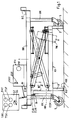
- the lying bed (1) shown on the head side has a frame (RG), which is provided on the head and foot sides with a lifting device, next to which wheel supports are arranged on both sides.
- a frame which is provided on the head and foot sides with a lifting device, next to which wheel supports are arranged on both sides.
- KH head-side lifting device
- RK head-side rolling supports
- the lifting device (KH) is in a lower position, in which the rollers (5) of the roller supports (RK) are still above the floor, which means that the bed has a firm footing.
- the lifting device (HK) is operated by the head-side motor (MK) with a gear via a lifting spindle depending on the current direction in the motor raising or lowering.
- MK head-side motor
- the support bracket (3) is raised so far that the bed can be rolled on the rollers (5).
- the bed frame (BR) together with the roller supports (RK) is raised far so that a patient can be cared for easily.
- the various adjustment positions are reported to the control device (ST) by means of cam-controlled switches.
- the cam (N) is shown arranged on a holding arm of the lifting frame and the cam switches on one of the roller supports (RK) are shown in the corresponding heights. Other locations can also be expertly selected, for example along the drive's spindle cylinder.
- KU the lower position of the bed frame (BR) before a rolling position (KR)
- EUK end contact
- the cam position end contact (ERK) is also controlled open by the cam (N).
- the cam (N) controls the upper end contact (EOK) open.
- the control cam lines are led into the control device (ST), from which lines to the head-side drive motor (MK) and to a power supply unit (NT), which includes a transformer and a rectifier contains, led.
- NT power supply unit
- a similar arrangement as the head-side is located at the foot end of the bed frame, and from there, from the foot-side lifting device (FH), which is only shown schematically, corresponding lines go from a foot-side roll position limit switch (ERF), a foot-side down position limit switch (EUF) and a foot-side up position limit switch (EOF) to the control device, which in turn controls the foot-side lifting motor (MF).
- FH foot-side lifting device
- a keypad with 4 control buttons, one of which is the upside down button (THK), one is the upside down button (TSK), one is the upside down button (THF) and one is the downside down button (TSF).
- a key switch SS is arranged there, which can only be actuated when the key is inserted and is intended for making special settings, namely the rollable position of the bed and the lowering of the head side.
- Figure 2 shows the circuit which has proven to be particularly advantageous and simple, but this can also be modified in a circuit-technically equivalent manner in which the provided decoupling diodes are replaced by changeover contacts and / or the changeover contacts by logic gate arrangements in a known manner.
- the control device is supplied with power via the transformer (TR) with a rectifier (GL) connected downstream.
- the head-side lifting button (THK) consists of a double-pole switch, whose Working contacts are made via the normally closed contacts of the head-side depression button (TSK) to the head-side motor (MK).
- TSK head-side depression button
- MK head-side motor
- the normally closed contacts of the head-side lifting button are led to a pair of changeover switches of the foot-side lifting button, the working contacts of which are led to the foot-side motor (MF) via normally closed contacts of the foot-side lowering button (TFS).
- MF foot-side motor
- TFS normally closed contacts of the foot-side lowering button
- the head side sink contact pair is supplied from the work side with the other power supply polarity at its work contacts, so that the reverse direction of rotation of the head side motor (MK) is controlled when the button is pressed.
- the working contacts of the head side depress button are accordingly supplied via normally closed contacts of the head side button and also via contacts of the foot side button, so that in turn a short-circuit locking is ensured.
- the lower side switch on the working contact side is supplied via the chaining of the normally closed contacts of the stroke switches (THK, THF) with a correspondingly reversed polarity, and its switching contacts are switched through to the lower side motor (MF).
- the lower end contact (EUK) In the lower end position, the lower end contact (EUK) is open, with the bed still standing firmly. If the key switch (SS) is actuated, the lower end contact (EUK) is bridged with its working contact (SA) via a diode (D5), so that a further lowering is possible when the depression button (TSK) is pressed into the rolling position until the roll position end contact (ERK) opens.
- SA working contact
- D5 diode
- a corresponding arrangement of the foot-side end contacts (EUF, ERF, EOF) and the associated diodes (D3, D4, D6) are placed in the feed line of the foot-side motor (MF), so that the entire arrangement works completely symmetrically.
- the Diodes (D5, D6) are used for the final coupling of the two motor leads when the key switch (SS) is actuated.
- the function of these two diodes can also be replaced by a pair of contacts on the key switch (SS).
- the circuit arrangement can also be transferred in its control and safety functions to a directional control that works with AC motors or to an electrically controlled hydraulic lifting device.
Landscapes
- Health & Medical Sciences (AREA)
- Nursing (AREA)
- Life Sciences & Earth Sciences (AREA)
- Animal Behavior & Ethology (AREA)
- General Health & Medical Sciences (AREA)
- Public Health (AREA)
- Veterinary Medicine (AREA)
- Invalid Beds And Related Equipment (AREA)
Description
- Die Erfindung betrifft eine Steuervorrichtung zur Betätigung von Hubvorrichtungen zum kopf- und/oder fußseitigen Anheben eines Matratzenrahmens, wobei von einer Gleichspannungsquelle ein Kopfseitenmotor über Kontakte eines Kopfseiten-Hubtasters hebend gerichtet und über Kontakte eines Kopfseiten-Senktasters senkend gerichtet zu bestromen ist und wobei am Fußseitenmotor über Kontakte eines Fußseiten-Hub-Tasters hebend gerichtet und über Kontakte eines Fußseiten-Senk-Tasters senkend gerichtet bestromen ist.
- In der Anmeldung DE-U-91 13 034 ist ein Pflegebett beschrieben, das kopf- und fußseitig je eine Hubvorrichtung aufweist, die über einzelne Steuertasten ein Heben sowie ein Senken der Kopfseite und desgleichen der Fußseite ermöglicht. Somit läßt sich das Bettgestell zur leichten Pflege und Behandlung des Liegenden beidseitig hochstellen oder einseitig relativ absenken, so daß der Kreislauf des Liegenden abhängig von einer jeweils gestellten Indikation angeregt oder entlastet wird.
- Weiterhin sind an dem Bettgestell rollfähige Stützen so angeordnet, daß in einer Extremstellung der Hubvorrichtung das Bettgestell auf deren Rollen verfahrbar ist. Etwas aus dieser Extremstellung herausgehoben hingegen, steht das Bett rutschfest auf den Hubvorrichungen. Die freie in die Sonderstellungen Steuerbarkeit birgt die Gefahr in sich, daß, wenn das Bett sich in der Rollstellung befindet, dieses wegrollen kann, sobald ein Patient daraus aufsteht oder sich hinein legt, wodurch dieser sturzgefährdet ist. Weiterhin ist insbesesondere die Kopftieflage häufig kontraindiziert. Es ist deshalb unzulässig, verwirrten Personen die Lagesteuerung selbst zu überlassen, da sie dies Gefahrensituationen nicht einschätzen oder erkennen können und Steuermaßnahmen zu deren Vermeidung oder Rückgängigmachung nicht vornehmen. Andererseits ist es erwünscht, daß ein Liegender sich selbst wahlweise in eine bequeme Kopfobenposition oder in eine hohe Bettlage oder in eine niedrige Aufstehposition mit dem Bett verbringen kann, so daß er dazu keinen Pfleger ordern muß.
- Es ist Aufgabe der Erfindung, eine Steuervorrichtung zu schaffen, die es ermöglicht, daß ein Liegender selbst alle solche und nur solche Bettpositionen ansteuern kann, die nicht sicherheitsgefährdend sind.
- Die Lösung der Aufgabe besteht darin, daß in der Zuleitung des Kopfseitenmotors ein Kopfunten-Endkontakt und in der Zuleitung des Fußseitenmotors ein Fußunten-Endkontakt jeweils seriell angeordnet sind, wobei diese Unten-Endkontakte jeweils vor einer Rollstellung des Bettgestelles betätigt angeordnet sind, daß zwischen die Zuleitungen der beiden Motore tastenseitig ein Ruhekontakt eines Schlüsselschalters überbrückend geschaltet ist und motorseitig diese Zuleitungen gegeneinander entkoppelt zu einem Arbeitskontakt des Schlüsselschalters geführt sind, welcher geschaltet die beiden Endkontakte brückt, und daß beide Motore einen gemeinsamen Rückleiter-Anschluß aufweisen.
- Vorteilhafte Ausgestaltungen sind in den Unteransprüchen angegeben.
- Diese Lösung ermöglicht es, daß nur derjenige Pfleger, der den Schlüsselschalter hat, mit diesem die Unten-Endschalter brücken kann, so daß dann die weitere Tastenbetätigung der Senken-Taster eine Verbringung des Bettes in die rollfähige Stellung bewirkt. Wird die Absenkung jedoch ohne eine Schlüsselbetätigung vorgenommen, so ergibt sich eine sichere untere Standstellung durch die Abschaltung der Endschalter. Nur eine Hubbetätigung der Steuerung ist dann noch wirksam.
- Der Schlüsselschalter hat vorteilhaft die weitere Funktion, eine aus Sicherheitsgründen vorgesehene Parallelsteuerung des Hebens und Senkens aufzutrennen, so daß eine beliebige Neigungsverstellung durch den Pfleger ermöglicht. ist. Die eingestellte Neigung bleibt, wenn der Schlüssel entfernt ist, solang erhalten, bis Endschalter das Heben oder Senken des angehobenen oder abgesenkten Endes begrenzen, so daß sich in der völligen Endstellung beider Bettenden und somit der Hubvorrichtungen die Horizontallage wieder ergibt.
- Vorteilhafte Ausgestaltungen sind in den Figuren 1 und 2 dargestellt.
- Fig. 1
- zeigt eine stirnseitige Ansicht eines Liegebettes mit schematisierter Steuervorrichtung;
- Fig. 2
- zeigt ein Schaltbild der Steuervorrichtung.
- Das kopfseitig gezeigte Liegebett (1) weist ein Rahmengestell (RG) auf, das kopf- und fußseitig jeweils mit einer Hubvorrichtung versehen ist, neben denen jeweils beidseitig Rollstützen angeordnet sind. In der Figur 1 sind lediglich die Kopfseitenhubvorrichtung (KH) sowie die Kopfseitenrollstützen (RK) zu sehen.
- Die Hubvorrichtung (KH) befindet sich in einer unteren Stellung, in der die Rollen (5) der Rollstützen (RK) sich noch über den Boden befinden, wodurch das Bett einen festen Stand hat. Die Hubvorrichtung (HK) wird durch den Kopfseitenmotor (MK) mit einem Getriebe über eine Hubspindel abhängig von der Stromrichtung im Motor anhebend oder absenkend betrieben. In der Stellung, in der die Spindel am weitestens eingezogen ist, ist der Tragbock (3) so weit angehoben, daß das Bett auf den Rollen (5) rollbar ist. In der anderen Extremlage der Hubvorrichtung ist der Bettrahmen (BR) zusammen mit den Rollstützen (RK) weit angehoben, so daß ein Patient leicht versorgt werden kann.
- Die verschiedenen Verstellpositionen werden mittels nockengesteuerter Schalter der Steuervorrichtung (ST) gemeldet. Der Übersichtlichkeit halber ist die Nocke (N) an einem Haltearm des Hubgestelles angeordnet dargestellt und sind die Nockenschalter an einer der Rollstützen (RK) in den entsprechenden Höhen eingezeichnet. Fachmännisch lassen sich auch andere Anbringungsorte wählen, z.B. entlang des Spindelzylinders des Antriebes. In der gezeigten Stellung (KU), der unteren Stellung des Bettrahmens (BR) vor einer Rollstellung (KR), ist nur der Endkontakt (EUK) der Kopfuntenstellung geöffnet betätigt. In der Rollstellung ist durch den Nocken (N) außerdem der Rollstellungsendkontakt (ERK) geöffnet gesteuert. In der extremen Hubstellung (HK) ist andererseits durch den Nocken (N) der obere Endkontakt (EOK) geöffnet gesteuert. Die Steuernockenleitungen sind in die Steuervorrichtung (ST) geführt, von der weiterhin Leitungen zu dem kopfseitigen Antriebsmotor (MK) und zu einem Netzteil (NT), welches einen Transformator und einen Gleichrichter enthält, geführt.
- Eine gleichartige Anordnung wie die kopfseitige befindet sich an dem Fußende des Bettgestelles, und von dort, von der fußseitigen Hubvorrichtung (FH), die nur schematisch dargestellt ist, gehen entsprechende Leitungen von einem fußseitigen Rollstellung-Endschalter (ERF), einem fußseitigen Untenstellung-Endschalter (EUF) und einem fußseitigen Obenstellung-Endschalter (EOF) an die Steuervorrichtung, die ihrerseits den fußseitigen Hubmotor (MF) ansteuert.
- Auf der Steuervorrichtung (ST) befindet sich ein Tastenfeld mit 4 Steuertasten, von denen eine die kopfseitige Hebentaste (THK), eine die kopfseitige Senkentaste (TSK), eine die fußseitige Hebentaste (THF) und eine die fußseitige Senkentaste (TSF) ist. Außerdem ist ein Schlüsselschalter (SS) dort angeordnet, der nur bei eingestecktem Schlüssel mit diesem zu betätigen ist und dazu vorgesehen ist, daß besondere Einstellungen, nämlich die rollfähige Stellung des Bettes und die Tiefstellung der Kopfseite vorgenommen werden können.
- Figur 2 zeigt die Schaltung die sich als besonders vorteilhaft und einfach erwiesen hat, diese läßt sich jedoch auch in schaltungstechnisch äquivalenter Weise abwandeln, in dem die vorgesehenen Entkopplungsdioden durch Umschaltkontakte und/oder die Umschaltkontakte durch logische Gatteranordnungen in bekannter Weise ersetzt werden.
- Die Stromversorgung der Steuervorrichtung erfolgt über den Transformator (TR) mit einem nachgeschalteten Gleichrichter (GL). Der kopfseitige Hebentaster (THK) besteht aus einem doppelpoligen Umschalter, dessen Arbeitskontakte über Ruhekontakte des kopfseitigen Senkentaster (TSK) zu dem Kopfseitenmotor (MK) geführt sind. Durch die Verknüpfung mit den Ruhekontakten des entgegengesetzt wirkenden Tasters wird ein Kurzschluß bei gemeinsamer Betätigung dieser Tasten verhindert. Die Ruhekontakte des Kopfseitenhebentasters sind auf ein Umschalterpaar des Fußseitenhebentaster geführt, dessen Arbeitskontakte über Ruhekontakte des Fußseitensenkentasters (TFS) zu dem Fußseitenmotor (MF) geführt sind. Auch hier ist eine Sicherheit entsprechend gegen einen Kurzschluß bei einer Parallelbetätigung widersprechender Tastenn über die Ruhekontaktverknüpfung gewährleistet.
- Das Kopfseitensenken-Kontaktpaar ist arbeitsseitig mit der anderen Stromversorgungspolarität an seinen Arbeitskontakten versorgt, so daß die umgekehrte Drehrichtung der Kopfseitenmotors (MK) bei der Tastenbetätigung gesteuert wird. Die Arbeitskontakte des Kopfseitensenkentasters sind entsprechend über Ruhekontakte des Kopfseitenhebentasters und auch über Ruhekontakte des Fußseitenhebentasters versorgt, so daß wiederum eine Kurzschlußverriegelung sichergestellt ist. Ebenso ist der Fußseitensenkentaster arbeitskontaktseitig über die Kettung der Ruhekontakte der Hubtaster (THK, THF) bei entsprechender umgekehrter Polarität versorgt, und dessen Schaltkontakte sind zu dem Fußseitenmotor (MF) durchgeschaltet.
- Soweit ist diese Schaltung in bisher üblichen Betthubvorrichtungen bekanntermaßen vorgesehen. Neu ist die Anordnung eines Schlüsselschalters (SS), dessen Ruhekontakt (SR) die beiden Zuleitungen der Motore (MK, MF) miteinander verbindet, so daß bei abgezogenen Schlüsselschalter (SS) beide Motore (MK, MF) bei der Betätigung einer oder beider Hubtasten (THK, THF) stets parallel hebend angesteuert werden und bei der Betätigung einer oder beider der Senkentasten (TSK, TSF) senkend betätigt werden. Wird der Schlüsselschalter (SS) jedoch betätigt, so tritt eine Auftrennung beider Stromkreise ein, und beide Motore (MK, MF) lassen sich in der eingangs beschriebenen Weise einzeln ansteuern.
- In der Zuleitung zu dem kopfseitigen Motor (MK) liegen jeweils seriell ein Untenstellungsendkontakt (EUK) und ein Rollstellungsendkontakt (ERK) sowie eine Diode (D2), die in der absenkenden Stromrichtung leitend ist. Parallel zu der Serienschaltung der Endkontakte (EUK, ERK) und der Diode (D2) ist eine Serienschaltung aus dem oberen Endkontakt (EOK) mit einer umgekehrt gerichteten Diode (D1) geschaltet. Befindet sich die Hubvorrichtung in der oberen Endlage, so ist der obere Endkontakt geöffnet, und es ist nur noch ein Betrieb in der umgekehrten Stromrichtung möglichst.
- In der unteren Endstellung ist der untere Endkontakt (EUK) geöffnet, wobei das Bett noch einen festen Stand hat. Falls der Schlüsselschalter (SS) betätigt ist, so wird mit dessen Arbeitskontakt (SA) der untere Endkontakt (EUK) über eine Diode (D5) gebrückt, so daß ein weiteres Absenken bei Betätigung der Senkentaste (TSK) in die Rollstellung möglich ist, bis der Rollstellungsendkontakt (ERK) öffnet.
- Eine entsprechende Anordnung der fußseitigen Endkontakte (EUF, ERF, EOF) sowie der zugehörigen Dioden (D3, D4, D6) sind in die Zuleitung des Fußseitenmotors (MF) gelegt, so daß die gesamte Anordnung völlig symmetrisch arbeitet. Die Dioden (D5, D6) dienen der Endkopplung der beiden Motorzuleitungen bei der Betätigung des Schlüsselschalters (SS). Diese beiden Dioden können auch durch ein Kontaktpaar des Schlüsselschalters (SS) in ihrer Funktion ersetzt werden.
- Die Schaltungsanordnung läßt sich auch in ihren Steuer- und Sicherheitsfunktionen auf eine Richtungssteuerung, die mit Wechselstrommotoren arbeitet oder auf eine elektrisch gesteuerte hydraulische Hebevorrichtungen übertragen.
Claims (6)
- Steuervorrichtung zur Betätigung von Hubvorrichtungen (KH, FH) zum kopf- und/oder fußseitigen Anheben eines Matratzenrahmens (MR), wobei von einer Gleichspannungsquelle ein Kopfseitenmotor (MK) über Kontakte eines Kopfseiten-Hubtasters (THK) hebend gerichtet und über Kontakte eines Kopfseiten-Senktasters (TSK) senkend gerichtet zu bestromen ist und wobei ein Fußseitenmotor (MF) über Kontakte eines Fußseiten-Hub-Tasters (THF) hebend gerichtet und über Kontakte eines Fußseiten-Senk-Tasters (TSF) senkend gerichtet zu bestromen ist, dadurch gekennzeichnet daß die beiden Motore (MK, MF) einen gemeinsamen Rückleiter-Anschluß aufweisen, daß in der Zuleitung des Kopfseitenmotores (MK) ein Kopfunten-Endkontakt (EUK) und in der Zuleitung des Fußseitenmotores (MF) ein Fußunten-Endkontakt (EUF) jeweils seriell angeordnet sind, wobei diese Unten-Endkontakte (EUK, EUF) jeweils vor einer Rollstellung des Bettgestelles (BG) betätigt angeordnet sind, und daß zwischen diesen Zuleitungen der beiden Motore (MK, MF) tastenseitig ein Ruhekontakt (SR) eines Schlüsselschalters (SS) überbrückend geschaltet ist und motorseitig diese Zuleitungen gegeneinander entkoppelt zu einem Arbeitskontakt (SA) des Schlüsselschalters (SS) geführt sind, der geschaltet die beiden Endkontakte (EUF, EUK) brückt.
- Steuervorrichtung nach Anspruch 1, dadurch gekennzeichnet, daß der Schlüsselschalter-Arbeitskontakt (SA) über Entkopplungsdioden (D5, D6) mit den motorseitigen Anschlüssen des Fußunten-Endkontaktes (EUF) und des Kopfunten-Endkontaktes (EUK) verbunden ist.
- Steuervorrichtung nach Anspruch 1 oder 2, dadurch gekennzeichnet, daß dem Fußunten-Endkontakt (EUF) ein Fußseiten-Rollstellungkontakt (ERF) und dem Kopfunten-Endkontakt (EUK) ein Kopfseiten-Rollstellungkontakt (ERK) motorseitig nachgeschaltet sind.
- Steuervorrichtung nach Anspruch 3, dadurch gekennzeichnet, daß in Serie mit dem Kopfseiten-Rollstellungkontakt (ERK) und dem Fußseiten-Rollstellungkontakt (ERF) jeweils eine Diode (D2, D4) in der senkenden Stromrichtung geschaltet ist und parallel zu dem Kopfunten-Endkontakt (EUK) und dem Kopfseiten-Rollstellungkontakt (ERK) ein Kopfoben-Endkontakt (EOK) in Serie mit einer Diode (D1) in hebender Stromrichtung geschaltet sind sowie parallel zu dem Fußunten-Endkontakt (EUF) und dem Fußseiten-Rollstellungkontakt (ERK) ein Fußoben-Endkontakt (EOF) in Serie mit einer weiteren Diode (D2) in hebender Stromrichtung geschaltet sind.
- Steuervorrichtung nach einem der vorstehenden Ansprüche, dadurch gekennzeichnet, daß an der Kopfseiten-Hubvorrichtung (KH) der Kopfoben-Endkontakt (EOK) in einer oberen Endstellung (KO) betätigt geöffnet angeordnet ist und der Kopfunten-Endkontakt (EUK) in einer ersten unteren Endstellung (KU) betätigt geöffnet angeordnet ist, in der eine Kopfseitenrollstütze (RK) gerade noch keinen Bodenkontakt hat, und daß an der Kopfseiten-Hubvorrichtung (KH) der Kopfseiten-Rollstellungkontakt (ERK) in einer zweiten, tieferen unteren Endstellung (KR) betätigt geöffnet angeordnet ist, in der die Kopfseitenrollstütze (RK) rollfähig unter die Kopfseiten-Hubvorrichtung (KH) hinausragt.
- Steuervorrichtung nach einem der vorstehenden Ansprüche, dadurch gekennzeichnet, daß an der Fußseiten-Hubvorrichtung (FH) der Fußoben-Endkontakt (EOF) in einer oberen Endstellung (KO) betätigt geöffnet angeordnet ist und der Fußunten-Endkontakt (EUF) in einer ersten unteren Endstellung betätigt geöffnet angeordnet ist, in der eine Fußseitenrollstütze gerade noch keinen rollfähigen Bodenkontakt hat, und daß an der Fußseiten-Hubvorrichtung (FH) der Fußseiten-Rollstellungkontakt (ERF) in einer zweiten, tieferen unteren Endstellung betätigt geöffnet angeordnet ist, in der die Fußseitenrollstütze rollfähig unter die Fußseiten-Hubvorrichtung (KF) hinausragt.
Applications Claiming Priority (2)
| Application Number | Priority Date | Filing Date | Title |
|---|---|---|---|
| DE4143182A DE4143182C2 (de) | 1991-12-30 | 1991-12-30 | Steuervorrichtung für eine Pflegebetthubvorrichtung |
| DE4143182 | 1991-12-30 |
Publications (3)
| Publication Number | Publication Date |
|---|---|
| EP0552502A2 EP0552502A2 (de) | 1993-07-28 |
| EP0552502A3 EP0552502A3 (en) | 1995-02-15 |
| EP0552502B1 true EP0552502B1 (de) | 1997-07-30 |
Family
ID=6448245
Family Applications (1)
| Application Number | Title | Priority Date | Filing Date |
|---|---|---|---|
| EP92122130A Expired - Lifetime EP0552502B1 (de) | 1991-12-30 | 1992-12-30 | Steuervorrichtung für eine Pflegebetthubvorrichtung |
Country Status (3)
| Country | Link |
|---|---|
| EP (1) | EP0552502B1 (de) |
| AT (1) | ATE156001T1 (de) |
| DE (1) | DE4143182C2 (de) |
Families Citing this family (4)
| Publication number | Priority date | Publication date | Assignee | Title |
|---|---|---|---|---|
| DE4406784C1 (de) * | 1994-03-02 | 1995-08-24 | Wissner Gmbh | Kranken- oder Pflegebett |
| DE20306066U1 (de) | 2003-04-16 | 2003-07-24 | Dewert Antriebs- Und Systemtechnik Gmbh & Co. Kg, 32278 Kirchlengern | Elektromotorischer Möbelantrieb |
| DE112008001447A5 (de) * | 2007-06-28 | 2010-08-05 | Linrot Holding Ag | Elektromotorischer Möbelantrieb |
| EP3081202A1 (de) * | 2015-04-13 | 2016-10-19 | Völker GmbH | Verfahren zum Steuern der Energiezufuhr zu Aktuatoren einer Liegefläche, Möbel dieser Art und Steuerung zum Steuern der Energiezufuhr zu Aktuatoren für derartige Möbel |
Family Cites Families (6)
| Publication number | Priority date | Publication date | Assignee | Title |
|---|---|---|---|---|
| US3174161A (en) * | 1961-05-08 | 1965-03-23 | American Seating Co | Hospital bed |
| US3697846A (en) * | 1971-02-11 | 1972-10-10 | American Hospital Supply Corp | Control system for hospital bed |
| US3742527A (en) * | 1972-03-01 | 1973-07-03 | Unlimited Dev Inc | Hospital bed |
| US4425673A (en) * | 1980-12-01 | 1984-01-17 | B-W Health Products, Inc. | Lifting system for adjustable hospital bed |
| US4953243A (en) * | 1989-08-09 | 1990-09-04 | Amedco Health Care, Inc. | Electronic control with emergency CPR feature for adjustable bed |
| DE9104892U1 (de) * | 1991-04-22 | 1991-07-25 | Kötter, Helmut, 4901 Hiddenhausen | Kranken- oder Pflegebett |
-
1991
- 1991-12-30 DE DE4143182A patent/DE4143182C2/de not_active Expired - Fee Related
-
1992
- 1992-12-30 AT AT92122130T patent/ATE156001T1/de not_active IP Right Cessation
- 1992-12-30 EP EP92122130A patent/EP0552502B1/de not_active Expired - Lifetime
Also Published As
| Publication number | Publication date |
|---|---|
| ATE156001T1 (de) | 1997-08-15 |
| DE4143182A1 (de) | 1993-07-01 |
| DE4143182C2 (de) | 1997-03-27 |
| EP0552502A2 (de) | 1993-07-28 |
| EP0552502A3 (en) | 1995-02-15 |
Similar Documents
| Publication | Publication Date | Title |
|---|---|---|
| DE69733092T2 (de) | Prozedurale Neigungsverstellungssteuerung für Krankentrage | |
| DE60311381T2 (de) | Elektrisches Bett und Steuerungseinrichtung und Steuerungsverfahren dafür | |
| DE3740710C2 (de) | ||
| WO2008113476A1 (de) | Pflegebett mit elektrischer notabsenkung | |
| EP0433737B1 (de) | Bett, insbesondere Kranken- und/oder Pflegebett | |
| DE69517713T2 (de) | Transfervorrichtung für Behinderte | |
| DE102005018686B4 (de) | Pflegebett mit Doppelmotorantrieb | |
| DE3876238T2 (de) | Doppelt hydraulisches krankenhausbett mit umgehungskreis. | |
| DE2340415A1 (de) | Krankenbett und steuergeraet fuer dieses | |
| EP1843732B1 (de) | Pflegebett mit symmetrierschaltung | |
| DE4416689C9 (de) | Bett, insbesondere Krankenbett | |
| DE4143182C2 (de) | Steuervorrichtung für eine Pflegebetthubvorrichtung | |
| DE60029101T2 (de) | Bett und Handschalter zur Steuerung von Verstellbewegungen | |
| DE2815763A1 (de) | Vorrichtung zum erleichtern des bettens von kranken | |
| EP0911013B1 (de) | Stehpult mit integrierter Aufstehhilfe | |
| DE102006030939B4 (de) | Elektrisches Wende-, Umlagerungs-, Kranken- und Pflegebett | |
| DE9117187U1 (de) | Steuervorrichtung für eine Pflegebetthubvorrichtung | |
| DE29623535U1 (de) | Hubvorrichtung für Sitz- oder Liegeflächen | |
| DE202011050361U1 (de) | Doppelbett | |
| DE9404944U1 (de) | Transportlifter für behinderte Personen | |
| EP0079998A1 (de) | Einlegerahmen für Sitz- und Liegemöbel | |
| EP2591759A1 (de) | Bett, insbesondere Kranken- oder Pflegebett | |
| EP1064904A2 (de) | Elektromotorische Antriebsanordnung für Möbel | |
| DE9318695U1 (de) | Kranken- oder Pflegebett | |
| DE202006010380U1 (de) | Elektrisches Wende-, Umlagerungs-, Kranken- und Pflegebett, sowie ein elektrischer Nachrüstsatz für alle Betten |
Legal Events
| Date | Code | Title | Description |
|---|---|---|---|
| PUAI | Public reference made under article 153(3) epc to a published international application that has entered the european phase |
Free format text: ORIGINAL CODE: 0009012 |
|
| AK | Designated contracting states |
Kind code of ref document: A2 Designated state(s): AT BE CH DE DK ES FR GB GR IE IT LI LU MC NL PT SE |
|
| RBV | Designated contracting states (corrected) |
Designated state(s): AT BE CH DK FR LI LU NL SE |
|
| REG | Reference to a national code |
Ref country code: DE Ref legal event code: 8566 |
|
| PUAL | Search report despatched |
Free format text: ORIGINAL CODE: 0009013 |
|
| RHK1 | Main classification (correction) |
Ipc: A61G 7/018 |
|
| AK | Designated contracting states |
Kind code of ref document: A3 Designated state(s): AT BE CH DE DK ES FR GB GR IE IT LI LU MC NL PT SE Kind code of ref document: A3 Designated state(s): AT BE CH DK FR LI LU NL SE |
|
| RIN1 | Information on inventor provided before grant (corrected) |
Inventor name: KOETTER, HELMUT |
|
| RAP1 | Party data changed (applicant data changed or rights of an application transferred) |
Owner name: WISSNER-BOSSERHOFF GMBH |
|
| 17P | Request for examination filed |
Effective date: 19950329 |
|
| RAP1 | Party data changed (applicant data changed or rights of an application transferred) |
Owner name: WISSNER-BOSSERHOFF GMBH & CO. KG |
|
| GRAG | Despatch of communication of intention to grant |
Free format text: ORIGINAL CODE: EPIDOS AGRA |
|
| 17Q | First examination report despatched |
Effective date: 19961115 |
|
| GRAH | Despatch of communication of intention to grant a patent |
Free format text: ORIGINAL CODE: EPIDOS IGRA |
|
| GRAH | Despatch of communication of intention to grant a patent |
Free format text: ORIGINAL CODE: EPIDOS IGRA |
|
| GRAA | (expected) grant |
Free format text: ORIGINAL CODE: 0009210 |
|
| AK | Designated contracting states |
Kind code of ref document: B1 Designated state(s): AT BE CH DK FR LI LU NL SE |
|
| PG25 | Lapsed in a contracting state [announced via postgrant information from national office to epo] |
Ref country code: FR Free format text: THE PATENT HAS BEEN ANNULLED BY A DECISION OF A NATIONAL AUTHORITY Effective date: 19970730 Ref country code: DK Effective date: 19970730 |
|
| REF | Corresponds to: |
Ref document number: 156001 Country of ref document: AT Date of ref document: 19970815 Kind code of ref document: T |
|
| REG | Reference to a national code |
Ref country code: CH Ref legal event code: EP |
|
| PG25 | Lapsed in a contracting state [announced via postgrant information from national office to epo] |
Ref country code: SE Effective date: 19971030 |
|
| ET | Fr: translation filed | ||
| PG25 | Lapsed in a contracting state [announced via postgrant information from national office to epo] |
Ref country code: BE Free format text: LAPSE BECAUSE OF NON-PAYMENT OF DUE FEES Effective date: 19971231 |
|
| PLBE | No opposition filed within time limit |
Free format text: ORIGINAL CODE: 0009261 |
|
| STAA | Information on the status of an ep patent application or granted ep patent |
Free format text: STATUS: NO OPPOSITION FILED WITHIN TIME LIMIT |
|
| BERE | Be: lapsed |
Owner name: WISSNER-BOSSERHOFF G.M.B.H. & CO. K.G. Effective date: 19971231 |
|
| 26N | No opposition filed | ||
| REG | Reference to a national code |
Ref country code: FR Ref legal event code: ST |
|
| PGFP | Annual fee paid to national office [announced via postgrant information from national office to epo] |
Ref country code: NL Payment date: 20071127 Year of fee payment: 16 Ref country code: LU Payment date: 20071212 Year of fee payment: 16 |
|
| PGFP | Annual fee paid to national office [announced via postgrant information from national office to epo] |
Ref country code: AT Payment date: 20071121 Year of fee payment: 16 Ref country code: CH Payment date: 20071115 Year of fee payment: 16 |
|
| REG | Reference to a national code |
Ref country code: CH Ref legal event code: PL |
|
| PG25 | Lapsed in a contracting state [announced via postgrant information from national office to epo] |
Ref country code: AT Free format text: LAPSE BECAUSE OF NON-PAYMENT OF DUE FEES Effective date: 20081230 |
|
| NLV4 | Nl: lapsed or anulled due to non-payment of the annual fee |
Effective date: 20090701 |
|
| PG25 | Lapsed in a contracting state [announced via postgrant information from national office to epo] |
Ref country code: LI Free format text: LAPSE BECAUSE OF NON-PAYMENT OF DUE FEES Effective date: 20081231 Ref country code: CH Free format text: LAPSE BECAUSE OF NON-PAYMENT OF DUE FEES Effective date: 20081231 |
|
| PG25 | Lapsed in a contracting state [announced via postgrant information from national office to epo] |
Ref country code: NL Free format text: LAPSE BECAUSE OF NON-PAYMENT OF DUE FEES Effective date: 20090701 |
|
| PG25 | Lapsed in a contracting state [announced via postgrant information from national office to epo] |
Ref country code: LU Free format text: LAPSE BECAUSE OF NON-PAYMENT OF DUE FEES Effective date: 20081230 |