EP0550969B1 - IC card connector supporting/fixing mechanism - Google Patents
IC card connector supporting/fixing mechanism Download PDFInfo
- Publication number
- EP0550969B1 EP0550969B1 EP92310929A EP92310929A EP0550969B1 EP 0550969 B1 EP0550969 B1 EP 0550969B1 EP 92310929 A EP92310929 A EP 92310929A EP 92310929 A EP92310929 A EP 92310929A EP 0550969 B1 EP0550969 B1 EP 0550969B1
- Authority
- EP
- European Patent Office
- Prior art keywords
- connector
- supporting part
- parts
- supporting
- holding parts
- Prior art date
- Legal status (The legal status is an assumption and is not a legal conclusion. Google has not performed a legal analysis and makes no representation as to the accuracy of the status listed.)
- Expired - Lifetime
Links
Images
Classifications
-
- B—PERFORMING OPERATIONS; TRANSPORTING
- B42—BOOKBINDING; ALBUMS; FILES; SPECIAL PRINTED MATTER
- B42D—BOOKS; BOOK COVERS; LOOSE LEAVES; PRINTED MATTER CHARACTERISED BY IDENTIFICATION OR SECURITY FEATURES; PRINTED MATTER OF SPECIAL FORMAT OR STYLE NOT OTHERWISE PROVIDED FOR; DEVICES FOR USE THEREWITH AND NOT OTHERWISE PROVIDED FOR; MOVABLE-STRIP WRITING OR READING APPARATUS
- B42D15/00—Printed matter of special format or style not otherwise provided for
- B42D15/02—Postcards; Greeting, menu, business or like cards; Letter cards or letter-sheets
-
- G—PHYSICS
- G06—COMPUTING OR CALCULATING; COUNTING
- G06K—GRAPHICAL DATA READING; PRESENTATION OF DATA; RECORD CARRIERS; HANDLING RECORD CARRIERS
- G06K19/00—Record carriers for use with machines and with at least a part designed to carry digital markings
- G06K19/06—Record carriers for use with machines and with at least a part designed to carry digital markings characterised by the kind of the digital marking, e.g. shape, nature, code
- G06K19/067—Record carriers with conductive marks, printed circuits or semiconductor circuit elements, e.g. credit or identity cards also with resonating or responding marks without active components
- G06K19/07—Record carriers with conductive marks, printed circuits or semiconductor circuit elements, e.g. credit or identity cards also with resonating or responding marks without active components with integrated circuit chips
- G06K19/077—Constructional details, e.g. mounting of circuits in the carrier
- G06K19/07743—External electrical contacts
-
- B—PERFORMING OPERATIONS; TRANSPORTING
- B42—BOOKBINDING; ALBUMS; FILES; SPECIAL PRINTED MATTER
- B42D—BOOKS; BOOK COVERS; LOOSE LEAVES; PRINTED MATTER CHARACTERISED BY IDENTIFICATION OR SECURITY FEATURES; PRINTED MATTER OF SPECIAL FORMAT OR STYLE NOT OTHERWISE PROVIDED FOR; DEVICES FOR USE THEREWITH AND NOT OTHERWISE PROVIDED FOR; MOVABLE-STRIP WRITING OR READING APPARATUS
- B42D25/00—Information-bearing cards or sheet-like structures characterised by identification or security features; Manufacture thereof
-
- G—PHYSICS
- G06—COMPUTING OR CALCULATING; COUNTING
- G06K—GRAPHICAL DATA READING; PRESENTATION OF DATA; RECORD CARRIERS; HANDLING RECORD CARRIERS
- G06K19/00—Record carriers for use with machines and with at least a part designed to carry digital markings
- G06K19/06—Record carriers for use with machines and with at least a part designed to carry digital markings characterised by the kind of the digital marking, e.g. shape, nature, code
- G06K19/067—Record carriers with conductive marks, printed circuits or semiconductor circuit elements, e.g. credit or identity cards also with resonating or responding marks without active components
- G06K19/07—Record carriers with conductive marks, printed circuits or semiconductor circuit elements, e.g. credit or identity cards also with resonating or responding marks without active components with integrated circuit chips
- G06K19/077—Constructional details, e.g. mounting of circuits in the carrier
Definitions
- the present invention relates to a mechanism for supporting and fixing a connector loaded on a main frame of an IC card together with a circuit substrate.
- FIG. 6 is an exploded perspective view of a conventional IC card.
- An IC card 10 comprises a main frame 2 and a circuit substrate 4 and a connector 1, both of which are loaded thereon.
- a circuit pattern 4b is formed on one or both of the sides of the circuit substrate 4, and a plurality of electronic parts 4a are mounted on the pattern 4b so as to be connected thereto.
- the circuit substrate 4 is supported by the inner side of a circuit substrate supporting/fixing part 2a of the main frame 2 and fixed thereto by caulking (not shown in the drawing) or the like.
- the connector 1 comprises a connector body part 1b having a plurality of external connection terminals la and holding parts 1c respectively formed on both sides of the body part 1b for the purpose of fixing the connector 1.
- the connector 1 is provided separately from the circuit substrate 4, and each of the external connection terminals la is electrically connected to the circuit pattern 4b of the substrate 4 by a lead wire (not shown) or the like.
- the external connection terminals 1a are exposed to air from the terminal surface of the connector body part 1b, which surface forms a surface on the insertion side of the IC card 10, so as to be connectable from the outside thereof.
- the lower connector-supporting part 2b of the main frame 2 is previously formed into a shape which engages with the lower half of the connector 1 so that the connector 1 is engaged with the connector-supporting part 2b.
- a sub-frame 3 which is previously formed into a shape which engages with the upper half of the connector 1 is fixed to the connector-supporting part 2b by an adhesive 7, with the connector 1 held therebetween (refer to Fig. 7), whereby the connector 1 is fixed.
- Fig. 7 is a partially sectional view taken along an arrow B in Fig. 6 and shows the state wherein the holding parts 1c of the connector 1 are engaged with the connector-supporting part 2b and the sub-frame 3 and fixed thereby after the IC card has been assembled.
- Metal panels 5 and 6 are bonded, by an adhesive (not shown), to both sides of the circuit substrate supporting/fixing part 2a of the main frame 2 on which the circuit substrate 4 is loaded so as to cover the both sides of the circuit substrate 4.
- the panels bonded respectively extend over the whole front and rear sides of the IC card 10, which include the surface portions of the connector supporting part 2b of the main frame 2, the sub-frame 3 and the connector body part 1b.
- the connector body part 1b of the connector 1 has substantially the same thickness (height) as that of the circuit substrate supporting/fixing part 2a of the main frame 2.
- Each of the holding parts 1c provided on both sides of the body part 1b has a shape having a width along the direction of card insertion and a thickness, both of which are smaller than those of the body part 1b.
- Both the connector supporting part 2b and the sub-frame 3 have a thickness (height) of about half that of the circuit substrate supporting/fixing part 2a or the body part 1b of the connector 1.
- the connector supporting part 2b has an opening 2c which is formed so as to engage with the lower half of the body part 1b of the connector 1 and recesses 2d which are formed so as to respectively engage with the lower halves of the holding parts 1c.
- the sub-frame 3 has an opening 3a which is formed so as to engage with the upper half of the body part 1b of the connector 1 and recesses 3b which are formed so as to respectively engage with the upper halves of the holding parts 1c.
- the opening 2c and the recesses 2d have the same shapes as those of the opening 3a and the recesses 3b, respectively.
- the sub-frame 3 is bonded to the connector supporting part 2b so that the connector 1 is vertically held between the connector supporting part 2b and the sub-frame 3 and fixed therebetween.
- the holding parts 1c of the connector 1 are respectively held and fixed between the upper and lower recesses 2d, 3b, and the body part 1b is engaged with the openings 2c, 3a and fixed thereby.
- the mechanism Since the conventional mechanism for supporting and fixing a connector in an IC card has the above configuration, the mechanism has the problem that, for example, when the card is dropped, if force is applied to the portion for fixing the connector, particularly, in the direction along the bonded surfaces of the connector supporting part of the main frame and the sub-frame, there is the danger of separation of the sub-frame from the connector supporting part and disassembling the card.
- the conventional mechanism has the other problem that when the connector is mounted during the process of assembling the IC card, much time is taken for adjusting the positions of the holding parts of the connector and the recesses of the connector supporting part and the sub-frame because of small allowable error of engagement therebetween.
- US-A-4 924 076 discloses an IC card connector supporting/fixing mechanism in accordance with the preamble of claim 1.
- the present invention has been achieved for solving the above-mentioned problems, to improve the mounting strength of a connector so as to prevent a card from being disassembled even if a mechanism for supporting and fixing the connector is subjected to force when the card is dropped or the like, and to facilitate the engagement between the connector supporting part of a main frame, the connector and a sub-frame during the process of assembling the IC card.
- the present invention provides an IC card connector supporting/fixing mechanism for supporting and fixing a connector provided with a plurality of external connector terminals to a portion of a main frame on the card insertion side at the position where a circuit substrate having electronic parts mounted thereon is provided, the mechanism comprising a connector comprising a connector body part having a terminal surface from which the plurality of external connector terminals electrically connected to the electronic parts mounted on the circuit substrate are exposed to air so as to be connectable from the outside, and holding parts which are respectively provided on both sides of the connector body part in the direction of card insertion, each of which has a width along the direction of card insertion and a thickness, both of which are smaller than those of the connector body part, and each of which has a surface on the card insertion side, the side surface along the direction of card insertion and a surface on the substrate side; a lower connector supporting part which is formed according to the shape of the lower half of the connector so that about a lower half of the connector is fitted thereinto, which has barrier parts each
- each of the barrier parts and the holding parts of the connector has tapered surfaces respectively provided at the edges thereof.
- the holding parts of the connector are respectively held by the barrier parts which are provided on the connector supporting part of the main frame and each of which has a height of half or more the thickness of the holding parts, even if force is applied in the direction along the bonded surfaces of the connector supporting part and the sub-frame, there is no danger of separation of the sub-frame from the connector supporting part because the whole force is received on the side of the connector supporting part provided with the barrier parts.
- the tapered surface is provided on each of the barrier parts and the holding parts of the connector, when the connector supporting part, the connector and the sub-frame are engaged with each other during the process of assembling an IC card, the mounting positions thereof can be corrected to regular positions even if there are deviations in the mounting positions.
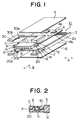
- Fig. 1 is an exploded perspective view of an IC card provided with a connector supporting/fixing mechanism in accordance with an embodiment of the present invention
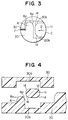
- Fig. 2 is a partially sectional view of a portion near a connector of the assembled IC card taken along the direction shown by an arrow B in Fig. 1
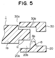
- Fig. 3 is an enlarged view of the portion in a circle C shown by a broken line in Fig. 2.
- the same reference numerals as those in the conventional IC card shown in Figs. 6 and 7 denote the same or equivalent portions which are not described below.
- a connector 1 is the same as the conventional connector, the surface on the card insertion side, the side surfaces and the surface on the substrate side of each of the holding parts 1c are denoted by 1e, 1f and 1g, respectively, for the sake of convenience of description.
- the lower connector supporting part 20 formed in a portion of the main frame 2 on the card insertion side and the sub-frame 30 which serves as an upper connector supporting part engaged with the supporting part 20 have a thickness (height) of about half that of the circuit substrate supporting/fixing part 2a or the body part 1b of the connector 1.
- the connector supporting part 20 has an opening 20a formed so as to engage with the lower half of the body part 1b of the connector 1 and recesses 20b formed so as to respectively engage with the lower halves of the holding parts 1c.
- Barrier parts 8 each having a height of half or more that of the holding parts 1c are respectively formed on portions of the recesses 20b, which respectively contact with the surfaces 1e of the holding parts 1c of the connector 1 on the card insertion side and the side surfaces 1f thereof.
- the sub-frame 30 has an opening 30a formed so as to engage with the upper half of the body part 1b of the connector 1 and recesses 30b formed so as to respectively engage with the upper halves of the holding parts 1c and the barrier parts 8 formed in the connector supporting part 20.
- the sub-frame 30 is engaged with the connector supporting part 20, with the connector 1 therebetween, and fixed to the connector supporting part 20 by fixing means such as an adhesive 7 or the like.
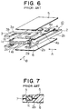
- Fig. 4 shows an exploded sectional view of the circumference of the connector 1 taken along the direction of the arrow B in Fig. 1
- Fig. 5 shows an exploded sectional view taken along the direction of the arrow A in Fig. 1.
- each of the recesses 30b formed in the sub-frame 30 has a size which can receive the upper half of each of the holding parts 1c of the connector 1 and each of the barrier parts 8 formed in the connector supporting part 20 in the directions of the arrows A and B in Fig. 1.
- a tapered surface 8a may be provided at the upper edge of each of the barrier parts 8.
- a tapered surface 1d may be formed at the edge of each of the holding parts 1c of the connector 1, which edge extends along the direction vertical to the direction of card insertion.
- the tapered surfaces 8a, 1d enable the connector 1, the connector supporting part 20 and the sub-frame 30 to be easily engaged with each other at regular positions thereof during the engaging process even if there is a position deviation in each of the parts.
- no barrier part 8 is provided on the portions of the recesses 20b of the connector supporting part 20, which respectively contact with the surfaces 1g of the holding parts 1c of the connector 1 on the substrate side. This is because when force is applied in the direction toward the surfaces 1g, the circuit substrate supporting/fixing part 2a receives the force because the surfaces 1g of the holding parts 1c on the substrate side are placed inside the card, and there is thus little possibility of separation of the sub-frame 3.
- the barrier parts 8 may be respectively provided on the portions of the recesses 20b, which respectively contact with the surfaces 1g of the holding parts 1c on the substrate side.
- the IC card connector supporting/fixing mechanism in accordance with the present invention comprises the barrier parts 8 which each have a height of half or more that of the holding parts 1c of the connector 1 and which are respectively formed on the recesses 20b of the connector supporting part 20 on the side of the main frame 2.
- the recesses 20b of the connector supporting part 20, on which the barrier are respectively formed receive the force applied in the direction along the bonded surfaces of the connector supporting part 20 and the sub-frame 30.
- the mechanism thus has the effect of making the sub-frame 30 difficult to separate.
- the mechanism since the tapered surfaces 8a, 1d are respectively provided at the upper edges of the barrier parts 8 and the edges of the holding parts 1c of the connector 1, the mechanism has the effect of enabling the connector 1, the connector supporting part 20 and the sub-frame 30 to be easily engaged with each other at regular positions during assembly even if there is a position deviation in each of the parts.
Landscapes
- Engineering & Computer Science (AREA)
- Computer Hardware Design (AREA)
- Microelectronics & Electronic Packaging (AREA)
- Physics & Mathematics (AREA)
- General Physics & Mathematics (AREA)
- Theoretical Computer Science (AREA)
- Credit Cards Or The Like (AREA)
- Coupling Device And Connection With Printed Circuit (AREA)
Applications Claiming Priority (2)
| Application Number | Priority Date | Filing Date | Title |
|---|---|---|---|
| JP4001417A JP3068301B2 (ja) | 1992-01-08 | 1992-01-08 | Icカード内のコネクタ支持固定機構 |
| JP1417/92 | 1992-01-08 |
Publications (3)
| Publication Number | Publication Date |
|---|---|
| EP0550969A2 EP0550969A2 (en) | 1993-07-14 |
| EP0550969A3 EP0550969A3 (cg-RX-API-DMAC7.html) | 1994-03-23 |
| EP0550969B1 true EP0550969B1 (en) | 1997-11-05 |
Family
ID=11500895
Family Applications (1)
| Application Number | Title | Priority Date | Filing Date |
|---|---|---|---|
| EP92310929A Expired - Lifetime EP0550969B1 (en) | 1992-01-08 | 1992-12-01 | IC card connector supporting/fixing mechanism |
Country Status (5)
| Country | Link |
|---|---|
| US (1) | US5288237A (cg-RX-API-DMAC7.html) |
| EP (1) | EP0550969B1 (cg-RX-API-DMAC7.html) |
| JP (1) | JP3068301B2 (cg-RX-API-DMAC7.html) |
| KR (1) | KR950004339B1 (cg-RX-API-DMAC7.html) |
| DE (1) | DE69223032T2 (cg-RX-API-DMAC7.html) |
Families Citing this family (13)
| Publication number | Priority date | Publication date | Assignee | Title |
|---|---|---|---|---|
| US5481434A (en) * | 1993-10-04 | 1996-01-02 | Molex Incorporated | Memory card and frame for assembly therefor |
| US5457606A (en) * | 1993-11-10 | 1995-10-10 | Raymond Engineering Inc. | Hermetically sealed PC card unit including a header secured to a connector |
| US5391083A (en) * | 1994-02-25 | 1995-02-21 | R. A. Tool & Die, Inc. | Computer card connector |
| GB9406854D0 (en) * | 1994-04-07 | 1994-06-01 | Gillette Co | Antiperspirants |
| US5526235A (en) * | 1994-06-23 | 1996-06-11 | Garmin Communication And Navigation | Electronic storage device and receptacle |
| JPH08255290A (ja) * | 1995-03-16 | 1996-10-01 | Alps Electric Co Ltd | 盗難監視装置 |
| US5833473A (en) * | 1997-03-12 | 1998-11-10 | Itt Manufacturing Enterprises, Inc. | Cardbus Bridge |
| US6282097B1 (en) | 1998-10-28 | 2001-08-28 | Garmin Corporation | Data card having a retractable handle |
| US6129321A (en) * | 1998-11-16 | 2000-10-10 | Garmin Corporation | Mounting apparatus for an electronic device |
| US6250553B1 (en) | 1998-12-30 | 2001-06-26 | Garmin Corporation | Data card having a retractable handle |
| US6466862B1 (en) * | 1999-04-19 | 2002-10-15 | Bruce DeKock | System for providing traffic information |
| US7908080B2 (en) | 2004-12-31 | 2011-03-15 | Google Inc. | Transportation routing |
| MX2015016263A (es) * | 2013-05-28 | 2016-04-18 | Neurophage Pharmaceuticals Inc | Polipeptidos que comprenden una secuencia de aminoacidos de bacteriofago modificado g3p con inmunogenicidad reducida. |
Family Cites Families (5)
| Publication number | Priority date | Publication date | Assignee | Title |
|---|---|---|---|---|
| US4798946A (en) * | 1987-04-09 | 1989-01-17 | Mitsubishi Denki Kabushiki Kaisha | Plastic package for an IC card |
| JP2539838B2 (ja) * | 1987-07-14 | 1996-10-02 | 三菱電機株式会社 | Icカ−ド装置 |
| US4887188A (en) * | 1987-12-22 | 1989-12-12 | Casio Computer Co., Ltd. | Connector for a memory card |
| US4900266A (en) * | 1989-03-08 | 1990-02-13 | Gsi Corporation | Strain relief system for connecting cables |
| CA2057518C (en) * | 1991-12-09 | 1996-11-19 | Albert John Kerklaan | Jacketted circuit card |
-
1992
- 1992-01-08 JP JP4001417A patent/JP3068301B2/ja not_active Expired - Fee Related
- 1992-11-19 US US07/979,005 patent/US5288237A/en not_active Expired - Lifetime
- 1992-12-01 DE DE69223032T patent/DE69223032T2/de not_active Expired - Fee Related
- 1992-12-01 EP EP92310929A patent/EP0550969B1/en not_active Expired - Lifetime
- 1992-12-21 KR KR1019920024867A patent/KR950004339B1/ko not_active Expired - Fee Related
Also Published As
| Publication number | Publication date |
|---|---|
| EP0550969A2 (en) | 1993-07-14 |
| JPH05185776A (ja) | 1993-07-27 |
| US5288237A (en) | 1994-02-22 |
| DE69223032D1 (de) | 1997-12-11 |
| DE69223032T2 (de) | 1998-03-26 |
| KR950004339B1 (ko) | 1995-04-28 |
| JP3068301B2 (ja) | 2000-07-24 |
| KR930016250A (ko) | 1993-08-26 |
| EP0550969A3 (cg-RX-API-DMAC7.html) | 1994-03-23 |
Similar Documents
| Publication | Publication Date | Title |
|---|---|---|
| EP0550969B1 (en) | IC card connector supporting/fixing mechanism | |
| US5477426A (en) | IC card with board positioning means | |
| US5434747A (en) | Photoelectric transducer | |
| EP1213741B1 (en) | Fuse box | |
| US6293818B1 (en) | Electrical connector for connecting a flexible printed circuit to a rigid printed circuit board | |
| US4915637A (en) | Function-preset wiring device for automobiles | |
| US4747019A (en) | Feedthrough capacitor arrangement | |
| EP0390295B1 (en) | Connector with means for securing to a substrate | |
| JPH0613136A (ja) | 同軸コネクタモジュール | |
| US5401189A (en) | Shield connector assembly | |
| US6811443B2 (en) | Electronic component having high mechanical strength and method of manufacturing a metal cover included in the electronic component | |
| US5867366A (en) | Electronic module and plastic substrate to accept and hold the electronic module | |
| JPH0828253B2 (ja) | 接地式電気コネクタ | |
| CA2174130C (en) | Ic card with board positioning means | |
| JPH0541584Y2 (cg-RX-API-DMAC7.html) | ||
| JPH05129043A (ja) | 基体に取付けるための固定手段を有するコネクタ | |
| EP1803195B1 (en) | Socket for digital camera module | |
| US5983491A (en) | I/O card and method making the same | |
| EP0301564B1 (en) | Automobile lamp assembly | |
| EP0910236B1 (en) | Electronic apparatus | |
| EP4429419A1 (en) | Housing for a printed circuit board (pcb) and pcb assembly | |
| JPS5932920B2 (ja) | 基板回路装置 | |
| EP0997982A2 (en) | Electrical connector for printed circuit boards | |
| JPH10243527A (ja) | 電気接続箱 | |
| JPS587678Y2 (ja) | シ−ルドケ−ス |
Legal Events
| Date | Code | Title | Description |
|---|---|---|---|
| PUAI | Public reference made under article 153(3) epc to a published international application that has entered the european phase |
Free format text: ORIGINAL CODE: 0009012 |
|
| AK | Designated contracting states |
Kind code of ref document: A2 Designated state(s): DE GB IT |
|
| PUAL | Search report despatched |
Free format text: ORIGINAL CODE: 0009013 |
|
| AK | Designated contracting states |
Kind code of ref document: A3 Designated state(s): DE GB IT |
|
| 17P | Request for examination filed |
Effective date: 19940727 |
|
| 17Q | First examination report despatched |
Effective date: 19960425 |
|
| GRAG | Despatch of communication of intention to grant |
Free format text: ORIGINAL CODE: EPIDOS AGRA |
|
| GRAH | Despatch of communication of intention to grant a patent |
Free format text: ORIGINAL CODE: EPIDOS IGRA |
|
| GRAH | Despatch of communication of intention to grant a patent |
Free format text: ORIGINAL CODE: EPIDOS IGRA |
|
| GRAA | (expected) grant |
Free format text: ORIGINAL CODE: 0009210 |
|
| AK | Designated contracting states |
Kind code of ref document: B1 Designated state(s): DE GB IT |
|
| ITF | It: translation for a ep patent filed | ||
| REF | Corresponds to: |
Ref document number: 69223032 Country of ref document: DE Date of ref document: 19971211 |
|
| REG | Reference to a national code |
Ref country code: GB Ref legal event code: 727 |
|
| REG | Reference to a national code |
Ref country code: GB Ref legal event code: 727A |
|
| PLBE | No opposition filed within time limit |
Free format text: ORIGINAL CODE: 0009261 |
|
| REG | Reference to a national code |
Ref country code: GB Ref legal event code: 727B |
|
| REG | Reference to a national code |
Ref country code: GB Ref legal event code: SP |
|
| 26N | No opposition filed | ||
| REG | Reference to a national code |
Ref country code: GB Ref legal event code: IF02 |
|
| PGFP | Annual fee paid to national office [announced via postgrant information from national office to epo] |
Ref country code: GB Payment date: 20071128 Year of fee payment: 16 |
|
| PGFP | Annual fee paid to national office [announced via postgrant information from national office to epo] |
Ref country code: IT Payment date: 20071228 Year of fee payment: 16 Ref country code: DE Payment date: 20071129 Year of fee payment: 16 |
|
| GBPC | Gb: european patent ceased through non-payment of renewal fee |
Effective date: 20081201 |
|
| PG25 | Lapsed in a contracting state [announced via postgrant information from national office to epo] |
Ref country code: DE Free format text: LAPSE BECAUSE OF NON-PAYMENT OF DUE FEES Effective date: 20090701 |
|
| PG25 | Lapsed in a contracting state [announced via postgrant information from national office to epo] |
Ref country code: GB Free format text: LAPSE BECAUSE OF NON-PAYMENT OF DUE FEES Effective date: 20081201 |
|
| PG25 | Lapsed in a contracting state [announced via postgrant information from national office to epo] |
Ref country code: IT Free format text: LAPSE BECAUSE OF NON-PAYMENT OF DUE FEES Effective date: 20081201 |