EP0548853A1 - Système de contrôle de distribution du couple entre les roues d'un axe commun - Google Patents
Système de contrôle de distribution du couple entre les roues d'un axe commun Download PDFInfo
- Publication number
- EP0548853A1 EP0548853A1 EP92121621A EP92121621A EP0548853A1 EP 0548853 A1 EP0548853 A1 EP 0548853A1 EP 92121621 A EP92121621 A EP 92121621A EP 92121621 A EP92121621 A EP 92121621A EP 0548853 A1 EP0548853 A1 EP 0548853A1
- Authority
- EP
- European Patent Office
- Prior art keywords
- clutch
- fact
- clutches
- axle
- torque
- Prior art date
- Legal status (The legal status is an assumption and is not a legal conclusion. Google has not performed a legal analysis and makes no representation as to the accuracy of the status listed.)
- Granted
Links
Images

Classifications
-
- F—MECHANICAL ENGINEERING; LIGHTING; HEATING; WEAPONS; BLASTING
- F16—ENGINEERING ELEMENTS AND UNITS; GENERAL MEASURES FOR PRODUCING AND MAINTAINING EFFECTIVE FUNCTIONING OF MACHINES OR INSTALLATIONS; THERMAL INSULATION IN GENERAL
- F16H—GEARING
- F16H48/00—Differential gearings
- F16H48/20—Arrangements for suppressing or influencing the differential action, e.g. locking devices
- F16H48/30—Arrangements for suppressing or influencing the differential action, e.g. locking devices using externally-actuatable means
- F16H48/32—Arrangements for suppressing or influencing the differential action, e.g. locking devices using externally-actuatable means using fluid pressure actuators
-
- B—PERFORMING OPERATIONS; TRANSPORTING
- B60—VEHICLES IN GENERAL
- B60K—ARRANGEMENT OR MOUNTING OF PROPULSION UNITS OR OF TRANSMISSIONS IN VEHICLES; ARRANGEMENT OR MOUNTING OF PLURAL DIVERSE PRIME-MOVERS IN VEHICLES; AUXILIARY DRIVES FOR VEHICLES; INSTRUMENTATION OR DASHBOARDS FOR VEHICLES; ARRANGEMENTS IN CONNECTION WITH COOLING, AIR INTAKE, GAS EXHAUST OR FUEL SUPPLY OF PROPULSION UNITS IN VEHICLES
- B60K17/00—Arrangement or mounting of transmissions in vehicles
- B60K17/04—Arrangement or mounting of transmissions in vehicles characterised by arrangement, location, or kind of gearing
- B60K17/16—Arrangement or mounting of transmissions in vehicles characterised by arrangement, location, or kind of gearing of differential gearing
- B60K17/20—Arrangement or mounting of transmissions in vehicles characterised by arrangement, location, or kind of gearing of differential gearing in which the differential movement is limited
-
- B—PERFORMING OPERATIONS; TRANSPORTING
- B60—VEHICLES IN GENERAL
- B60K—ARRANGEMENT OR MOUNTING OF PROPULSION UNITS OR OF TRANSMISSIONS IN VEHICLES; ARRANGEMENT OR MOUNTING OF PLURAL DIVERSE PRIME-MOVERS IN VEHICLES; AUXILIARY DRIVES FOR VEHICLES; INSTRUMENTATION OR DASHBOARDS FOR VEHICLES; ARRANGEMENTS IN CONNECTION WITH COOLING, AIR INTAKE, GAS EXHAUST OR FUEL SUPPLY OF PROPULSION UNITS IN VEHICLES
- B60K23/00—Arrangement or mounting of control devices for vehicle transmissions, or parts thereof, not otherwise provided for
- B60K23/04—Arrangement or mounting of control devices for vehicle transmissions, or parts thereof, not otherwise provided for for differential gearing
-
- F—MECHANICAL ENGINEERING; LIGHTING; HEATING; WEAPONS; BLASTING
- F16—ENGINEERING ELEMENTS AND UNITS; GENERAL MEASURES FOR PRODUCING AND MAINTAINING EFFECTIVE FUNCTIONING OF MACHINES OR INSTALLATIONS; THERMAL INSULATION IN GENERAL
- F16H—GEARING
- F16H48/00—Differential gearings
- F16H48/20—Arrangements for suppressing or influencing the differential action, e.g. locking devices
- F16H48/22—Arrangements for suppressing or influencing the differential action, e.g. locking devices using friction clutches or brakes
-
- F—MECHANICAL ENGINEERING; LIGHTING; HEATING; WEAPONS; BLASTING
- F16—ENGINEERING ELEMENTS AND UNITS; GENERAL MEASURES FOR PRODUCING AND MAINTAINING EFFECTIVE FUNCTIONING OF MACHINES OR INSTALLATIONS; THERMAL INSULATION IN GENERAL
- F16H—GEARING
- F16H48/00—Differential gearings
- F16H48/20—Arrangements for suppressing or influencing the differential action, e.g. locking devices
- F16H2048/204—Control of arrangements for suppressing differential actions
-
- F—MECHANICAL ENGINEERING; LIGHTING; HEATING; WEAPONS; BLASTING
- F16—ENGINEERING ELEMENTS AND UNITS; GENERAL MEASURES FOR PRODUCING AND MAINTAINING EFFECTIVE FUNCTIONING OF MACHINES OR INSTALLATIONS; THERMAL INSULATION IN GENERAL
- F16H—GEARING
- F16H48/00—Differential gearings
- F16H48/38—Constructional details
- F16H48/42—Constructional details characterised by features of the input shafts, e.g. mounting of drive gears thereon
- F16H2048/423—Constructional details characterised by features of the input shafts, e.g. mounting of drive gears thereon characterised by bearing arrangement
-
- F—MECHANICAL ENGINEERING; LIGHTING; HEATING; WEAPONS; BLASTING
- F16—ENGINEERING ELEMENTS AND UNITS; GENERAL MEASURES FOR PRODUCING AND MAINTAINING EFFECTIVE FUNCTIONING OF MACHINES OR INSTALLATIONS; THERMAL INSULATION IN GENERAL
- F16H—GEARING
- F16H48/00—Differential gearings
- F16H48/06—Differential gearings with gears having orbital motion
- F16H48/08—Differential gearings with gears having orbital motion comprising bevel gears
-
- F—MECHANICAL ENGINEERING; LIGHTING; HEATING; WEAPONS; BLASTING
- F16—ENGINEERING ELEMENTS AND UNITS; GENERAL MEASURES FOR PRODUCING AND MAINTAINING EFFECTIVE FUNCTIONING OF MACHINES OR INSTALLATIONS; THERMAL INSULATION IN GENERAL
- F16H—GEARING
- F16H48/00—Differential gearings
- F16H48/38—Constructional details
- F16H48/40—Constructional details characterised by features of the rotating cases
Definitions
- the present invention relates to a system for instantaneously controlling torque distribution between the wheels of a common vehicle axle.
- the present invention relates to a system of the type comprising a pair of axle shafts, each connected angularly integral with a respective drive wheel on the vehicle; an input shaft for transmitting torque; and a differential for transmitting motion from the input shaft to the axle shafts; the differential presenting a planet carrier, a ring gear meshing with the input shaft and integral with the planet carrier, and a pair of sun gears.
- torque distribution between the two axle shafts may be effected either equally, using traditional differentials, or in different percentages, using special differentials, each with its own torque distribution range.
- the type of differential selected according to the operating conditions of the vehicle univocally determines the manner in which torque is distributed between the vehicle wheels.
- a system for instantaneously controlling torque distribution between the wheels of a common vehicle axle comprising a pair of axle shafts, each connected angularly integral with a respective drive wheel on the vehicle; an input shaft for transmitting torque; and a differential for transmitting motion from said input shaft to said axle shafts; the differential presenting a planet carrier angularly integral with said input shaft, and a pair of sun gears; characterized by the fact that it comprises first releasable angular connecting means interposed between each said axle shaft and a respective said sun gear; and second releasable angular connecting means interposed between each said axle shaft and said planet carrier; control means being provided for so controlling said first and second angular connecting means as to continuously vary distribution of said torque between said axle shafts.
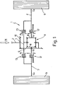
- Number 1 in the accompanying drawings indicates a system for instantaneously controlling torque distribution between the wheels of a common vehicle axle, which system 1 comprises an input shaft 2; a pair of axle shafts 3, 4, each connected to a respective wheel 5 (Fig.1) on the vehicle (not shown); and a differential 6 for transmitting motion from input shaft 2 to axle shafts 3, 4.
- Differential 6 comprises a planet carrier 7; a pair of sun gears 8; and a ring gear 9 integral with planet carrier 7 and meshing with a gear 10 fitted on to input shaft 2.
- system 1 For each axle shaft 3, 4, system 1 comprises a first and second multiple-disk clutch 12 and 13 arranged adjacent to each other and interposed between differential 6 and each axle shaft 3, 4. System 1 also comprises a control device 14 for controlling clutches 12 and 13 and continuously varying the distribution between axle shafts 3 and 4 of torque M supplied by input shaft 2.
- clutches 12 and 13 of each axle shaft 3, 4 present a common bell 16 connected angularly integral, in known manner, with respective axle shaft 3, 4; and respective hubs 17 and 18 respectively connected angularly integral with a respective sun gear 8 and planet carrier 7.
- device 14 for clutches 12 and 13 of each axle shaft 3, 4, device 14 comprises an elastic element 19, conveniently a Belleville washer, interposed between end disk 20 of first clutch 12 and end wall 21 of bell 16, and which provides for controlling closure of first clutch 12; and a first hydraulic actuator 22 in turn comprising a first annular hydraulic piston 23 located on the opposite side of first and second clutches 12 and 13 in relation to elastic element 19, and which is moved inside a chamber 24 by pressurized fluid fed into chamber 24.
- elastic element 19 conveniently a Belleville washer
- First actuator 22 also comprises a number of first rods 25 (only one of which is shown in Fig.2) interposed between first piston 23 and end disk 20 of first clutch 12, and cooperating with first piston 23 so as to exert force on first clutch 12, more specifically on end disk 20 of first clutch 12, in opposition to the force exerted by elastic element 19.
- device 14 also comprises a number of second rods 26 (only one of which is shown) interposed between end disk 20 of first clutch 12 and a corresponding end disk 27 of second clutch 13, adjacent to first clutch 12.
- device 14 also comprises a second hydraulic piston 28 coaxial with and adjacent to first hydraulic piston 22, and which is moved inside a chamber 29 by pressurized fluid fed into chamber 29, for controlling closure of second clutch 13.
- second rods 26 are activated indirectly by second piston 28, and provide for exerting on end disk 20 of first clutch 12 a force in opposition to that exerted by elastic element 19, and substantially proportional to the force exerted by second piston 28 on second clutch 13.
- second pistons 28 close respective second clutches 13, the disks of which are packed between respective second rods 26 and second pistons 28, thus providing substantially for a direct drive condition by virtue of excluding differential 6.
- Fluid feed into the left chamber 24, on the other hand, provides for moving respective piston 23, which cooperates with rods 25 so as to open respective first clutch 12. More specifically, pistons 23 are controlled by a single pressure signal p (Fig.1) so as to continuously regulate the torque transmitted by clutches 12 as a function of torque M , and so gradually transfer torque from clutches 12 to 13, with no noticeable interruption in operation.
- Clutches 13 are controlled by two different pressure signals p1 and p2 (Fig.1).
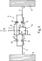
- the Fig.3 variation relates to a system 31, which differs from system 1 by virtue of clutches 12 and 13 of each axle shaft 3, 4 being controlled independently.
- second rods 26 are dispensed with, so that clutches 12, instead of being opened automatically as respective clutches 13 are closed, are opened directly by respective pistons 23 and respective first rods 24, which are controlled as described previously.
- system 31 differs from system 1 (Fig.2) by virtue of having no second rods 26, and by virtue of comprising, for each second clutch 13, a fixed axial reference, preferably a retaining ring (not shown), for axially retaining disk 27 and so enabling closure of second clutch 13 by piston 28.
- Systems 1 and 31 thus provide for two advantages. Firstly, they provide for continuously varying the distribution of torque M between axle shafts 3 and 4 and, consequently, between wheels 5 of the vehicle (not shown), thus enabling the vehicle to adapt continuously to any operating condition.
- first and second clutches 12 and 13 provide for active distribution of torque M , that is, for "translating” or rather transferring the torque on each wheel from one wheel 5 to the other, with no loss in torque.
- torque transfer from one wheel to the other is achieved in extremely straightforward manner, more specifically by supplying a control signal, in the example shown a hydraulic signal, for controlling one or other of second hydraulic pistons 28.
Landscapes
- Engineering & Computer Science (AREA)
- General Engineering & Computer Science (AREA)
- Mechanical Engineering (AREA)
- Chemical & Material Sciences (AREA)
- Combustion & Propulsion (AREA)
- Transportation (AREA)
- Physics & Mathematics (AREA)
- Analytical Chemistry (AREA)
- Fluid Mechanics (AREA)
- Retarders (AREA)
- Arrangement And Driving Of Transmission Devices (AREA)
- Arrangement And Mounting Of Devices That Control Transmission Of Motive Force (AREA)
Applications Claiming Priority (2)
| Application Number | Priority Date | Filing Date | Title |
|---|---|---|---|
| ITTO911006A IT1250886B (it) | 1991-12-20 | 1991-12-20 | Sistema per il controllo della ripartizione della coppia motrice tra le ruote di uno stesso assale di un veicolo. |
| ITTO911006 | 1991-12-20 |
Publications (2)
| Publication Number | Publication Date |
|---|---|
| EP0548853A1 true EP0548853A1 (fr) | 1993-06-30 |
| EP0548853B1 EP0548853B1 (fr) | 1996-05-01 |
Family
ID=11409810
Family Applications (1)
| Application Number | Title | Priority Date | Filing Date |
|---|---|---|---|
| EP92121621A Expired - Lifetime EP0548853B1 (fr) | 1991-12-20 | 1992-12-18 | Système de contrÔle de distribution du couple entre les roues d'un axe commun |
Country Status (6)
| Country | Link |
|---|---|
| US (1) | US5295921A (fr) |
| EP (1) | EP0548853B1 (fr) |
| JP (1) | JPH0616057A (fr) |
| DE (1) | DE69210372T2 (fr) |
| ES (1) | ES2086056T3 (fr) |
| IT (1) | IT1250886B (fr) |
Cited By (8)
| Publication number | Priority date | Publication date | Assignee | Title |
|---|---|---|---|---|
| EP0662402A1 (fr) * | 1993-12-29 | 1995-07-12 | CENTRO RICERCHE FIAT S.p.A. | Différentiel commandé électroniquement avec système de contrôle pour la répartition du couple |
| GB2321287A (en) * | 1997-01-16 | 1998-07-22 | Tochigi Fuji Sangyo Kk | Control of the distribution of torque to the output shafts of differential gearing |
| EP0926397A3 (fr) * | 1997-12-23 | 2000-11-08 | ANTONIO CARRARO S.p.A. | Système d'entraínement pour véhicules utilisés dans le domaine de l'agriculture, pépinière, jardinage et similaire |
| US6393351B2 (en) | 2000-06-05 | 2002-05-21 | C.R.F. Societa Consortile Per Azioni | System for the active control of a motor vehicle differential |
| EP1281560A2 (fr) * | 2001-08-03 | 2003-02-05 | GKN Automotive Inc. | Module d'essieu intégré avec double commande de couple électronique |
| US7713159B2 (en) | 2006-04-10 | 2010-05-11 | Gkn Driveline Torque Technology Kk | Power transmitting apparatus |
| US7951036B2 (en) | 2005-04-28 | 2011-05-31 | Magna Powertrain Ag & Co Kg | Differential transmission unit featuring active controlling of the moment distribution |
| DE102022103838A1 (de) | 2022-02-17 | 2023-08-17 | Audi Aktiengesellschaft | Antriebsvorrichtung für eine Fahrzeugachse |
Families Citing this family (13)
| Publication number | Priority date | Publication date | Assignee | Title |
|---|---|---|---|---|
| US5582557A (en) * | 1995-06-07 | 1996-12-10 | Titan Wheel International, Inc. | Hydraulically-operable locking differential with in-line piston means |
| IT1284942B1 (it) * | 1996-10-11 | 1998-05-28 | Gkn Birfield Ag | Gruppo di innesto in particolare per autoveicoli |
| JP3652462B2 (ja) * | 1997-01-14 | 2005-05-25 | 本田技研工業株式会社 | 車両用リヤディファレンシャルのケーシング構造 |
| US6378677B1 (en) * | 2000-10-03 | 2002-04-30 | Honda Giken Kogyo Kabushiki Kaisha | Power transmission device having electromagnetic clutch |
| US20030224896A1 (en) * | 2002-05-15 | 2003-12-04 | I-Chao Chung | Hydraulic differential lock |
| US7037231B2 (en) * | 2004-03-08 | 2006-05-02 | Borgwarner, Inc. | Variable biasing differential |
| DE102005018907A1 (de) * | 2005-04-22 | 2006-11-09 | Zf Friedrichshafen Ag | Ausgleichsgetriebe für eine elektrisch angetriebene Antriebsachse |
| US8132638B2 (en) * | 2008-10-03 | 2012-03-13 | Eaton Corporation | Rear drive module wheel disconnect |
| WO2011097237A1 (fr) * | 2010-02-02 | 2011-08-11 | Eaton Corporation | Dispositif de modulation de couple hydraulique autonome |
| US9855843B2 (en) | 2016-02-24 | 2018-01-02 | Cnh Industrial America Llc | System and method for controlling the speed of a track-driven work vehicle based on monitored loads to avoid track overheating |
| US10017035B2 (en) | 2016-02-24 | 2018-07-10 | Cnh Industrial America Llc | System and method for controlling a multi-axle work vehicle based on axle loading |
| DE102017128113B4 (de) * | 2017-11-28 | 2023-12-28 | Gkn Automotive Ltd. | Verfahren zur Steuerung eines Antriebssystems für mindestens eine Achse eines Kraftfahrzeuges |
| CN111043274B (zh) * | 2019-12-31 | 2021-01-19 | 代道洋 | 双路径耦合传动差速器 |
Citations (4)
| Publication number | Priority date | Publication date | Assignee | Title |
|---|---|---|---|---|
| DE3545540A1 (de) * | 1985-12-21 | 1987-07-02 | Audi Ag | Antriebsvorrichtung fuer ein vierradgetriebenes kraftfahrzeug |
| EP0241382A1 (fr) * | 1986-04-10 | 1987-10-14 | Automobiles Peugeot | Pont arrière pour véhicule à quatre roues motrices |
| GB2210341A (en) * | 1987-10-01 | 1989-06-07 | Man Nutzfahrzeuge Gmbh | Vehicle transmission |
| EP0511067A1 (fr) * | 1991-04-26 | 1992-10-28 | Glaenzer Spicer | Dispositif de transmission à viscocoupleur contrôlé, notamment pour véhicule automobile |
Family Cites Families (7)
| Publication number | Priority date | Publication date | Assignee | Title |
|---|---|---|---|---|
| JPS6294421A (ja) * | 1985-10-18 | 1987-04-30 | Fuji Heavy Ind Ltd | 車両の後輪駆動装置 |
| DE3814206A1 (de) * | 1988-04-27 | 1989-11-09 | Viscodrive Gmbh | Selbsttaetig begrenzt sperrendes kegelradausgleichsgetriebe, insbesondere fuer kraftfahrzeuge |
| FR2634847B1 (fr) * | 1988-07-27 | 1990-11-09 | Peugeot | Systeme differentiel a glissement variable controlee |
| WO1990005250A1 (fr) * | 1988-11-11 | 1990-05-17 | Zahnradfabrik Friedrichshafen Ag | Differentiel avec embrayage a friction |
| US5098360A (en) * | 1988-12-26 | 1992-03-24 | Tochigifujisangyo Kabushiki Kaisha | Differential gear with limited slip and locking mechanism |
| JPH03243421A (ja) * | 1990-02-19 | 1991-10-30 | Mazda Motor Corp | 車両の動力伝達装置 |
| JPH04123934A (ja) * | 1990-09-17 | 1992-04-23 | Iseki & Co Ltd | 乗用型田植機の後輪伝動装置 |
-
1991
- 1991-12-20 IT ITTO911006A patent/IT1250886B/it active IP Right Grant
-
1992
- 1992-12-18 DE DE69210372T patent/DE69210372T2/de not_active Expired - Lifetime
- 1992-12-18 ES ES92121621T patent/ES2086056T3/es not_active Expired - Lifetime
- 1992-12-18 US US07/993,088 patent/US5295921A/en not_active Expired - Fee Related
- 1992-12-18 EP EP92121621A patent/EP0548853B1/fr not_active Expired - Lifetime
- 1992-12-21 JP JP4340681A patent/JPH0616057A/ja active Pending
Patent Citations (4)
| Publication number | Priority date | Publication date | Assignee | Title |
|---|---|---|---|---|
| DE3545540A1 (de) * | 1985-12-21 | 1987-07-02 | Audi Ag | Antriebsvorrichtung fuer ein vierradgetriebenes kraftfahrzeug |
| EP0241382A1 (fr) * | 1986-04-10 | 1987-10-14 | Automobiles Peugeot | Pont arrière pour véhicule à quatre roues motrices |
| GB2210341A (en) * | 1987-10-01 | 1989-06-07 | Man Nutzfahrzeuge Gmbh | Vehicle transmission |
| EP0511067A1 (fr) * | 1991-04-26 | 1992-10-28 | Glaenzer Spicer | Dispositif de transmission à viscocoupleur contrôlé, notamment pour véhicule automobile |
Cited By (12)
| Publication number | Priority date | Publication date | Assignee | Title |
|---|---|---|---|---|
| EP0662402A1 (fr) * | 1993-12-29 | 1995-07-12 | CENTRO RICERCHE FIAT S.p.A. | Différentiel commandé électroniquement avec système de contrôle pour la répartition du couple |
| GB2321287A (en) * | 1997-01-16 | 1998-07-22 | Tochigi Fuji Sangyo Kk | Control of the distribution of torque to the output shafts of differential gearing |
| GB2321287B (en) * | 1997-01-16 | 1999-01-13 | Tochigi Fuji Sangyo Kk | Differential apparatus |
| US5910064A (en) * | 1997-01-16 | 1999-06-08 | Tochigi Fuji Sangyo Kabushiki Kaisha | Differential apparatus |
| EP0926397A3 (fr) * | 1997-12-23 | 2000-11-08 | ANTONIO CARRARO S.p.A. | Système d'entraínement pour véhicules utilisés dans le domaine de l'agriculture, pépinière, jardinage et similaire |
| US6393351B2 (en) | 2000-06-05 | 2002-05-21 | C.R.F. Societa Consortile Per Azioni | System for the active control of a motor vehicle differential |
| EP1281560A2 (fr) * | 2001-08-03 | 2003-02-05 | GKN Automotive Inc. | Module d'essieu intégré avec double commande de couple électronique |
| EP1281560A3 (fr) * | 2001-08-03 | 2005-12-21 | GKN Driveline North America, Inc. | Module d'essieu intégré avec double commande de couple électronique |
| US7951036B2 (en) | 2005-04-28 | 2011-05-31 | Magna Powertrain Ag & Co Kg | Differential transmission unit featuring active controlling of the moment distribution |
| US7713159B2 (en) | 2006-04-10 | 2010-05-11 | Gkn Driveline Torque Technology Kk | Power transmitting apparatus |
| DE102007016599B4 (de) * | 2006-04-10 | 2012-09-20 | Gkn Driveline Torque Technology Kk | Kraftübertragungsvorrichtung |
| DE102022103838A1 (de) | 2022-02-17 | 2023-08-17 | Audi Aktiengesellschaft | Antriebsvorrichtung für eine Fahrzeugachse |
Also Published As
| Publication number | Publication date |
|---|---|
| EP0548853B1 (fr) | 1996-05-01 |
| ES2086056T3 (es) | 1996-06-16 |
| DE69210372D1 (de) | 1996-06-05 |
| IT1250886B (it) | 1995-04-21 |
| DE69210372T2 (de) | 1996-10-31 |
| JPH0616057A (ja) | 1994-01-25 |
| US5295921A (en) | 1994-03-22 |
| ITTO911006A1 (it) | 1993-06-20 |
| ITTO911006A0 (it) | 1991-12-20 |
Similar Documents
| Publication | Publication Date | Title |
|---|---|---|
| EP0548853B1 (fr) | Système de contrÔle de distribution du couple entre les roues d'un axe commun | |
| US5415598A (en) | Vehicular left/right drive torque adjusting apparatus | |
| EP0262434B1 (fr) | Dispositif de restriction du différentiel interaxial pour véhicules à quatre roues motrices | |
| EP1010565B1 (fr) | Mécanisme de changement de gamme synchronisé pour boíte de transfert | |
| US8986148B2 (en) | Single speed and two-speed disconnecting axle arrangements | |
| US7175558B2 (en) | Torque vectoring drive units with worm driven ball screw clutches | |
| US4412459A (en) | Controlled differential | |
| EP0943479B1 (fr) | Mécanisme de changement de gamme synchronisée pour boíte de transfert | |
| US2353554A (en) | Endless track vehicle | |
| US20150266374A1 (en) | Disconnectable driveline for all-wheel drive vehicle | |
| US6745879B1 (en) | Hydromechanical coupling with clutch assembly and magnetorheological clutch actuator | |
| US6988602B2 (en) | Torque transfer coupling with magnetorheological clutch actuator | |
| JPH0477166B2 (fr) | ||
| US6851537B2 (en) | Worm driven ball screw actuator for traction clutches | |
| GB2115506A (en) | Three mode differential | |
| GB2032022A (en) | Hydraulically - operated countershaft change-speed gear | |
| US4727954A (en) | Power transmitting system for a four-wheel drive vehicle | |
| US4744437A (en) | Power transmitting system for a four-wheel drive vehicle | |
| EP0274167B1 (fr) | Transmission de puissance pour un véhicule à quatre roues motrices | |
| US5098352A (en) | Disengageable four-wheel-drive transmission system for motor vehicles | |
| US4605084A (en) | Constant mesh gear transmission | |
| GB2264988A (en) | Double clutch arrangement | |
| US4790211A (en) | Power transmission device for four wheel drive vehicle having an improved differential motion limiting mechanism | |
| US4974714A (en) | Clutch assembly and improved low pressure control therefor | |
| US4787269A (en) | Power transmitting system for a four-wheel drive vehicle |
Legal Events
| Date | Code | Title | Description |
|---|---|---|---|
| PUAI | Public reference made under article 153(3) epc to a published international application that has entered the european phase |
Free format text: ORIGINAL CODE: 0009012 |
|
| AK | Designated contracting states |
Kind code of ref document: A1 Designated state(s): DE ES FR GB IT SE |
|
| RAP1 | Party data changed (applicant data changed or rights of an application transferred) |
Owner name: CENTRO RICERCHE FIAT SOCIETA CONSORTILE PER AZIONI |
|
| 17P | Request for examination filed |
Effective date: 19931227 |
|
| 17Q | First examination report despatched |
Effective date: 19950220 |
|
| GRAH | Despatch of communication of intention to grant a patent |
Free format text: ORIGINAL CODE: EPIDOS IGRA |
|
| GRAA | (expected) grant |
Free format text: ORIGINAL CODE: 0009210 |
|
| AK | Designated contracting states |
Kind code of ref document: B1 Designated state(s): DE ES FR GB IT SE |
|
| ITF | It: translation for a ep patent filed |
Owner name: STUDIO TORTA SOCIETA' SEMPLICE |
|
| REF | Corresponds to: |
Ref document number: 69210372 Country of ref document: DE Date of ref document: 19960605 |
|
| REG | Reference to a national code |
Ref country code: ES Ref legal event code: FG2A Ref document number: 2086056 Country of ref document: ES Kind code of ref document: T3 |
|
| ET | Fr: translation filed | ||
| PLBE | No opposition filed within time limit |
Free format text: ORIGINAL CODE: 0009261 |
|
| STAA | Information on the status of an ep patent application or granted ep patent |
Free format text: STATUS: NO OPPOSITION FILED WITHIN TIME LIMIT |
|
| 26N | No opposition filed | ||
| REG | Reference to a national code |
Ref country code: GB Ref legal event code: IF02 |
|
| PGFP | Annual fee paid to national office [announced via postgrant information from national office to epo] |
Ref country code: ES Payment date: 20081201 Year of fee payment: 17 |
|
| PGFP | Annual fee paid to national office [announced via postgrant information from national office to epo] |
Ref country code: SE Payment date: 20081211 Year of fee payment: 17 |
|
| PGFP | Annual fee paid to national office [announced via postgrant information from national office to epo] |
Ref country code: GB Payment date: 20081230 Year of fee payment: 17 |
|
| EUG | Se: european patent has lapsed | ||
| GBPC | Gb: european patent ceased through non-payment of renewal fee |
Effective date: 20091218 |
|
| PG25 | Lapsed in a contracting state [announced via postgrant information from national office to epo] |
Ref country code: GB Free format text: LAPSE BECAUSE OF NON-PAYMENT OF DUE FEES Effective date: 20091218 |
|
| REG | Reference to a national code |
Ref country code: ES Ref legal event code: FD2A Effective date: 20110324 |
|
| PGFP | Annual fee paid to national office [announced via postgrant information from national office to epo] |
Ref country code: IT Payment date: 20101215 Year of fee payment: 19 |
|
| PG25 | Lapsed in a contracting state [announced via postgrant information from national office to epo] |
Ref country code: SE Free format text: LAPSE BECAUSE OF NON-PAYMENT OF DUE FEES Effective date: 20091219 |
|
| PGFP | Annual fee paid to national office [announced via postgrant information from national office to epo] |
Ref country code: DE Payment date: 20101215 Year of fee payment: 19 |
|
| PG25 | Lapsed in a contracting state [announced via postgrant information from national office to epo] |
Ref country code: ES Free format text: LAPSE BECAUSE OF NON-PAYMENT OF DUE FEES Effective date: 20110310 |
|
| PG25 | Lapsed in a contracting state [announced via postgrant information from national office to epo] |
Ref country code: ES Free format text: LAPSE BECAUSE OF NON-PAYMENT OF DUE FEES Effective date: 20091219 |
|
| PGFP | Annual fee paid to national office [announced via postgrant information from national office to epo] |
Ref country code: FR Payment date: 20111219 Year of fee payment: 20 |
|
| REG | Reference to a national code |
Ref country code: DE Ref legal event code: R071 Ref document number: 69210372 Country of ref document: DE |
|
| REG | Reference to a national code |
Ref country code: DE Ref legal event code: R071 Ref document number: 69210372 Country of ref document: DE |