EP0548832B1 - Dispositif d'ancrage pour la barre de tension d'une ancre en laminé de fibres - Google Patents
Dispositif d'ancrage pour la barre de tension d'une ancre en laminé de fibres Download PDFInfo
- Publication number
- EP0548832B1 EP0548832B1 EP92121570A EP92121570A EP0548832B1 EP 0548832 B1 EP0548832 B1 EP 0548832B1 EP 92121570 A EP92121570 A EP 92121570A EP 92121570 A EP92121570 A EP 92121570A EP 0548832 B1 EP0548832 B1 EP 0548832B1
- Authority
- EP
- European Patent Office
- Prior art keywords
- thread
- ribs
- anchoring
- anchor member
- rod
- Prior art date
- Legal status (The legal status is an assumption and is not a legal conclusion. Google has not performed a legal analysis and makes no representation as to the accuracy of the status listed.)
- Expired - Lifetime
Links
- 238000004873 anchoring Methods 0.000 title claims abstract description 89
- 230000009471 action Effects 0.000 claims abstract description 5
- 238000010008 shearing Methods 0.000 claims abstract description 5
- 239000004567 concrete Substances 0.000 claims abstract description 3
- 238000005065 mining Methods 0.000 claims abstract description 3
- 230000003014 reinforcing effect Effects 0.000 claims abstract 8
- 239000000835 fiber Substances 0.000 claims description 36
- 229910000831 Steel Inorganic materials 0.000 claims description 23
- 239000010959 steel Substances 0.000 claims description 23
- 239000002131 composite material Substances 0.000 claims description 18
- 239000000463 material Substances 0.000 claims description 8
- 229920003002 synthetic resin Polymers 0.000 claims description 4
- 239000000057 synthetic resin Substances 0.000 claims description 4
- 239000011159 matrix material Substances 0.000 claims description 3
- 239000011513 prestressed concrete Substances 0.000 claims description 2
- 229920002994 synthetic fiber Polymers 0.000 claims 1
- 230000000694 effects Effects 0.000 abstract description 6
- 230000008859 change Effects 0.000 abstract description 3
- 238000004049 embossing Methods 0.000 abstract 1
- 230000002787 reinforcement Effects 0.000 description 23
- 230000005540 biological transmission Effects 0.000 description 10
- 239000004033 plastic Substances 0.000 description 9
- 229920003023 plastic Polymers 0.000 description 9
- 239000011435 rock Substances 0.000 description 7
- 230000007797 corrosion Effects 0.000 description 5
- 238000005260 corrosion Methods 0.000 description 5
- 238000004804 winding Methods 0.000 description 5
- 238000010521 absorption reaction Methods 0.000 description 2
- 239000004760 aramid Substances 0.000 description 2
- 229920003235 aromatic polyamide Polymers 0.000 description 2
- 238000009412 basement excavation Methods 0.000 description 2
- 230000008901 benefit Effects 0.000 description 2
- 230000015572 biosynthetic process Effects 0.000 description 2
- 238000010276 construction Methods 0.000 description 2
- 239000002657 fibrous material Substances 0.000 description 2
- 238000005755 formation reaction Methods 0.000 description 2
- 239000003365 glass fiber Substances 0.000 description 2
- 238000004519 manufacturing process Methods 0.000 description 2
- 238000000926 separation method Methods 0.000 description 2
- OKTJSMMVPCPJKN-UHFFFAOYSA-N Carbon Chemical compound [C] OKTJSMMVPCPJKN-UHFFFAOYSA-N 0.000 description 1
- 229920000049 Carbon (fiber) Polymers 0.000 description 1
- 229920000914 Metallic fiber Polymers 0.000 description 1
- 239000004952 Polyamide Substances 0.000 description 1
- 238000004026 adhesive bonding Methods 0.000 description 1
- 238000000418 atomic force spectrum Methods 0.000 description 1
- 229910052799 carbon Inorganic materials 0.000 description 1
- 239000004917 carbon fiber Substances 0.000 description 1
- 230000001419 dependent effect Effects 0.000 description 1
- 239000003822 epoxy resin Substances 0.000 description 1
- 230000002349 favourable effect Effects 0.000 description 1
- 230000006872 improvement Effects 0.000 description 1
- 238000002347 injection Methods 0.000 description 1
- 239000007924 injection Substances 0.000 description 1
- 238000001746 injection moulding Methods 0.000 description 1
- 238000003780 insertion Methods 0.000 description 1
- 230000037431 insertion Effects 0.000 description 1
- 230000009916 joint effect Effects 0.000 description 1
- 229920002647 polyamide Polymers 0.000 description 1
- 229920000647 polyepoxide Polymers 0.000 description 1
- 229920000642 polymer Polymers 0.000 description 1
- 230000009467 reduction Effects 0.000 description 1
- 239000007787 solid Substances 0.000 description 1
- 210000002435 tendon Anatomy 0.000 description 1
- 239000004753 textile Substances 0.000 description 1
- 229920001169 thermoplastic Polymers 0.000 description 1
- 229920001187 thermosetting polymer Polymers 0.000 description 1
- 239000004416 thermosoftening plastic Substances 0.000 description 1
- XLYOFNOQVPJJNP-UHFFFAOYSA-N water Substances O XLYOFNOQVPJJNP-UHFFFAOYSA-N 0.000 description 1
Images


Classifications
-
- E—FIXED CONSTRUCTIONS
- E21—EARTH DRILLING; MINING
- E21D—SHAFTS; TUNNELS; GALLERIES; LARGE UNDERGROUND CHAMBERS
- E21D21/00—Anchoring-bolts for roof, floor in galleries or longwall working, or shaft-lining protection
- E21D21/0026—Anchoring-bolts for roof, floor in galleries or longwall working, or shaft-lining protection characterised by constructional features of the bolts
-
- E—FIXED CONSTRUCTIONS
- E04—BUILDING
- E04C—STRUCTURAL ELEMENTS; BUILDING MATERIALS
- E04C5/00—Reinforcing elements, e.g. for concrete; Auxiliary elements therefor
- E04C5/07—Reinforcing elements of material other than metal, e.g. of glass, of plastics, or not exclusively made of metal
-
- E—FIXED CONSTRUCTIONS
- E04—BUILDING
- E04C—STRUCTURAL ELEMENTS; BUILDING MATERIALS
- E04C5/00—Reinforcing elements, e.g. for concrete; Auxiliary elements therefor
- E04C5/08—Members specially adapted to be used in prestressed constructions
- E04C5/12—Anchoring devices
- E04C5/125—Anchoring devices the tensile members are profiled to ensure the anchorage, e.g. when provided with screw-thread, bulges, corrugations
-
- E—FIXED CONSTRUCTIONS
- E21—EARTH DRILLING; MINING
- E21D—SHAFTS; TUNNELS; GALLERIES; LARGE UNDERGROUND CHAMBERS
- E21D21/00—Anchoring-bolts for roof, floor in galleries or longwall working, or shaft-lining protection
- E21D21/0006—Anchoring-bolts for roof, floor in galleries or longwall working, or shaft-lining protection characterised by the bolt material
-
- F—MECHANICAL ENGINEERING; LIGHTING; HEATING; WEAPONS; BLASTING
- F16—ENGINEERING ELEMENTS AND UNITS; GENERAL MEASURES FOR PRODUCING AND MAINTAINING EFFECTIVE FUNCTIONING OF MACHINES OR INSTALLATIONS; THERMAL INSULATION IN GENERAL
- F16B—DEVICES FOR FASTENING OR SECURING CONSTRUCTIONAL ELEMENTS OR MACHINE PARTS TOGETHER, e.g. NAILS, BOLTS, CIRCLIPS, CLAMPS, CLIPS OR WEDGES; JOINTS OR JOINTING
- F16B33/00—Features common to bolt and nut
- F16B33/02—Shape of thread; Special thread-forms
-
- Y—GENERAL TAGGING OF NEW TECHNOLOGICAL DEVELOPMENTS; GENERAL TAGGING OF CROSS-SECTIONAL TECHNOLOGIES SPANNING OVER SEVERAL SECTIONS OF THE IPC; TECHNICAL SUBJECTS COVERED BY FORMER USPC CROSS-REFERENCE ART COLLECTIONS [XRACs] AND DIGESTS
- Y10—TECHNICAL SUBJECTS COVERED BY FORMER USPC
- Y10S—TECHNICAL SUBJECTS COVERED BY FORMER USPC CROSS-REFERENCE ART COLLECTIONS [XRACs] AND DIGESTS
- Y10S411/00—Expanded, threaded, driven, headed, tool-deformed, or locked-threaded fastener
- Y10S411/904—Fastener or fastener element composed of nonmetallic material
- Y10S411/908—Resinous material
Definitions
- the invention relates to a device for anchoring a rod-shaped tension member made of fiber composite material with unidirectional fibers embedded in a matrix of synthetic resin, in particular for use as an anchor element in foundation or mining, as a reinforcement element for concrete, in particular prestressed concrete, or the like.
- Tension members made of high-strength fiber composite materials have a lower specific weight, but above all a higher corrosion resistance. Because of these properties, such tension members could therefore be used with advantage as anchor elements in foundations and mines, where aggressive water often occurs, which poses a risk of corrosion for steel tension members.
- Tension members made of fiber composite materials also behave similarly to those made of steel, i.e. they have an essentially linear stress-strain line. In contrast to steel tension members, they have no yield point; on the contrary, they break when their tensile strength is reached without previous plastic deformation. This property and, in contrast to their tensile strength in the longitudinal direction of the fibers, only low transverse compressive strength prevent the anchoring devices which are otherwise known and proven in the construction industry from being adopted directly.
- Fiber composite materials are problematic because the tensile force of the tension member in the area of the threads is essentially transmitted to the respective anchoring element by axial thrust forces, which cause shear stresses in the threads.
- axial thrust forces which cause shear stresses in the threads.
- breaking of the fiber strand in radial planes or also shearing off of cylindrical outer areas in relation to cylindrical inner areas in the threaded area of rod-shaped tension members it is known to arrange the fibers in an outer area in alternating oblique directions and to link them with a textile link to anchor deeper fibers (DE-OS 35 04 829). The shear effect also remains dominant for the stress on a thread produced in this way.
- a buffer layer as a plasticizing zone between a tension member made of fiber composite material and an anchoring body made of steel, especially between the thread flanks of these two elements which are in engagement with one another (DE-OS 38 34 266).
- the strength of the material used for this buffer layer must be less than the strength of the fiber composite material on transverse pressure, so that large deformations with a small increase in stress are possible under load from a certain compressive stress.
- the profiling of the tension member which may consist of an asymmetrical trapezoidal thread
- the tension member which may consist of an asymmetrical trapezoidal thread
- an anchoring element as a nut made of plastic, in which the threads are reinforced by a reinforcement consisting of warp and weft (EP 0 403 940 A1). This also does not reduce the shear stress in the threads of the tension rod.
- the invention has for its object to find a training for thread anchoring taking into account the strength properties of fiber composite materials, in which the dangerous shear stresses in the thread are avoided as well as the additional effort for introducing a buffer layer as a plasticizing zone.
- the anchoring device combines the effects of screw anchoring with those of a wedge anchoring. Due to the comparatively flat angle of attack of the flanks of the threaded ribs, the radial contact pressure on the tension rod is increased in the case of an anchoring body which is rigid against ring tensile forces; this leads to a greater depth effect and thus to a higher shear resistance.
- the anchoring body not only carries the internal thread required for the screwing action and absorbs the axial thrust forces, but also acts as an annular sleeve for the wedge action.
- the flat angle of attack also allows good insertion of the originally unidirectional fibers into the thread profile during the manufacture of the tension rod that the individual thread ribs are filled with the full fiber density of the rod cross-section.
- a further improvement in the power transmission can be achieved in that the unidirectional fiber arrangement in the anchoring area is changed in such a way that internal fibers are also guided outward and thus come within a short distance of the immediate area of influence of the wedge clamping force.
- a tension rod made of fiber composite material can in principle be anchored by means of an anchoring body made of steel.
- certain properties of the fiber composite material e.g. the corrosion resistance, depending on its application, it is desirable to have these properties also with the anchoring element.
- Tension members made of fiber composite materials suffer significantly higher elongations than corresponding tension members made of steel due to the lower modulus of elasticity under the same load. Since the tension rod is stretched under load in the area of a screwable anchoring body, while the anchoring body supported against a fixed abutment is compressed, high stress concentrations result especially at the end facing the supporting surface of the anchoring body, while there are still reserves at the opposite free end of the anchoring body that cannot be used.
- the ring tensile stiffness of the anchoring element can be changed over its cross section in a relatively simple manner. Since components made of plastic generally do not have sufficient strength to absorb the ring tensile forces, additional measures are required to absorb the ring tensile forces, e.g. a corresponding reinforcement, which also serves to absorb the axial shear forces or can consist of different reinforcement elements.
- the ring tensile stiffness can therefore also be changed via the cross-section of the reinforcement, wherein either the cross-section of the reinforcement elements themselves can be changed or additional reinforcement elements can also be inserted at certain points.
- a typical application for a tension screw element made of fiber composite material according to the invention is the securing of rock formations in the area of an eruption e.g. for a tunnel.
- Fig. 1 is shown in a cross section a pilot tunnel 1 initially opened, from which rock anchors 2 are driven radially into the mountains 3.
- Each rock anchor 2 consists in each case of a tension rod 5 inserted into a borehole 4 with an air-side anchorage 6. Injection of hardening material into the borehole 4 fixes the tension rod 5 therein so that it can be tensioned with respect to the excavation surface 7.
- tension rods made of fiber composite materials compared to those made of steel has, in addition to the lower weight and the higher corrosion resistance, the advantage that the tension rods 5 can be destroyed by means of forces acting transversely to their longitudinal axis when the hatched cross section 8 breaks out later.
- the tension rod 5 consists of a fiber composite material of appropriate strength. Glass fibers are particularly suitable as fiber material because their lateral compressive strength is relatively high compared to other fibers. The fibers are expediently embedded in a matrix made of epoxy resin.
- the rod 5 is provided on its surface with a profile, which forms a thread 9 from thread ribs 10 and thread grooves 11. A nut in the form of an anchoring body 12 is screwed onto the thread of the rod 5 and is supported against an anchor plate 13 which in turn rests on the breakout surface 7.
- FIGS. 1 and 2 The representation of the invention on the basis of such a rock anchor according to FIGS. 1 and 2 is only to be understood as an example;
- the invention can of course also be used with all other tension screw elements, in particular with tendons, both for anchoring and for connecting rods made of fiber composite materials with a corresponding design.
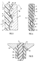
- Fig. 3 which shows only a small section in longitudinal section of the force transmission area between the tension rod 5 and the anchoring body 12, shows the arranged on the surface of the rod 5 thread 9 from threaded ribs 10 and intervening thread grooves 11.
- the thread 9 is designed as a flat trapezoidal thread, in which the flanks 14 between the thread ribs 10 and the thread fillets 11 are arranged at an angle alpha to the longitudinal axis of the rod, which in the exemplary embodiment shown is approximately 30 degrees.
- Another conceivable thread shape would also be a flat cord thread.
- the anchoring body 12 screwed onto the tension rod 5 consists, as usual, of steel; but he can also consist of fiber composite materials.
- the anchoring body 12 has on its inner surface a profile corresponding to the rod thread, in turn made of thread ribs 15 and thread flutes 16, between which the thread flanks 17 run in the same way at the angle alpha to the rod longitudinal axis as the flanks 14 of the rod thread.
- the magnitude of the radial force R is, as in the case of wedge anchoring, dependent on the angle alpha at which the flanks 14 and 17 are inclined against the longitudinal axis of the tension rod 5.
- Inclines are provided, namely such that the pitch of the nut thread is slightly larger than the pitch of the rod thread.
- the thread on the tension rod 5 is advantageously produced in that a radial pressure is applied to the rod 5 during the hardening of the synthetic resin enveloping and gluing together from the outside in a radial direction, through which the thread flutes 11 are produced as impressions.
- the unidirectional fibers are not cut up by this, but merely deflected somewhat in their course.
- the unidirectional fiber arrangement in the anchoring area is changed such that the inner fibers 19 are also guided outwards and thus for a short length are arranged in the immediate area of influence of the clamping action.
- FIG. 4 represents a partial longitudinal section through a rod 5 in the threaded area.
- the thread formation according to the invention in which the flanks 14 of the threaded ribs 10 are only slightly inclined against the longitudinal axis of the tension rod 5, generates strong transverse pressures on the tension rod itself, which must be absorbed as ring tensile forces by an anchoring or connecting element having the internal thread.
- an anchoring or connecting element consist of a tensile material, such as Steel, then these ring tensile stresses are absorbed with little deformation, even with small wall thicknesses, because the body with the internal thread also acts as a ring sleeve.
- Fiber composite material such as corrosion resistance, which dictate the application
- other materials especially plastics, are often used for the anchoring element.
- Pure plastics, such as thermoplastics or thermosets, are not suitable for absorbing high ring tensile stresses, so that the function of a ring sleeve cannot be easily achieved.
- an anchoring element made of a combined material namely plastic and tensile material, are shown, which can be manufactured economically and which allows both the high ring tensile forces to be absorbed by the flat thread and the to ensure axial power transmission in the thread.
- FIG. 5 shows an anchoring device for a tension rod 5 similar to FIG. 2 with an anchoring body 20 made of plastic, which has an internal thread and - to achieve a certain joint effect - rests with a spherical segment surface 21 against a correspondingly designed surface 22 of an anchor plate 23.
- a reinforcement 24 is formed in the threaded area of the anchoring body 20.
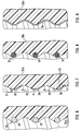
- 6 to 8 show different embodiments for such low-expansion, tensile reinforcements formed in the thread region of the anchoring element.
- Reinforcements of this type are particularly effective if they follow the thread course in a helical shape and lie in or in the region of the thread tip of the internal thread of the anchoring body 20 ; there they achieve a particularly high reinforcement effect because they serve to absorb the ring tensile stresses as well as the axial shear stresses.
- a spiral 25 made of round steel (FIG. 6) is particularly simple, the windings 26 of which lie in the thread tips and directly form the thread profile in this highly stressed area.
- a very uniform load and favorable load transmission is achieved by a steel band 27 (Fig. 7), which also extends helically and whose windings 28 reinforce both the flank 30 which is most heavily loaded, namely in the direction of the arrows 29, and the thread tip 31 Back of this band 27 can also with profiles 32, for example Grooves, ribs or the like can be provided to improve the adhesion.
- bundles or strips 33 made of the finest wires or fibers both metallic, in particular steel fibers, and non-metallic fibers, e.g. made of carbon, aramid or the like can be used (Fig. 8).
- Their adaptability to shape also allows windings to be perpendicular to the longitudinal axis, i.e. not along the screw line determined by the thread.
- a closed thread profile 34 e.g. embossed from a tube, wound helically or longitudinally welded, this can be used as the core in an injection molding tool for producing the anchoring body 20, which leads to a simplification of the production.
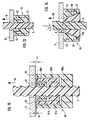
- FIGS. 10 to 12 also show how a ring tensile stiffness that is variable over the height of the anchoring body can be achieved through the choice or arrangement of the reinforcement elements.
- FIG. 10 shows a section corresponding to FIG. 3 from the force transmission area between a tension rod 5 and an anchoring body 40 made of plastic, which is provided with a spiral reinforcement 41 in the area of the thread profile.
- the direction of the anchoring force acting on the tension rod 5 is again indicated by an arrow 18.
- the individual windings 41a, b and c have different cross sections, which, with a corresponding shape, are achieved by different thicknesses of the steel strip forming the coil.
- the upper turn 41a facing the support surface has a smaller cross-section than the following turn 41b, which in turn has a smaller cross-section than the next following turn 41c, etc.
- FIG. 11 a section between the thread profile of an anchoring body 40a shows a separation between the Reinforcement elements are shown, which serve the transmission of the axial shear forces and the reinforcement elements, which are provided for receiving the ring tensile forces.
- the transmission of the axial thrust forces is served by a helix 42 covering the flanks of the threaded ribs facing the load and the peaks and valleys, which in this case could also consist of individual parts.
- a steel wire helix 43 is embedded in the ribs and runs through the entire height of the anchoring body 40a.
- the change in the ring tensile stiffness is served by an additional helix 44, which can optionally also be followed by a further, appropriately arranged helix.
- the partial longitudinal section through an anchoring body 40b according to FIG. 12 also shows a separation between the axial thrust forces and the reinforcement elements absorbing the ring tensile forces.
- the thread profiling here is followed by a closed sleeve 45, while the anchoring body 40b itself to absorb the ring tensile forces in a manner known per se Embedding of fibrous materials is capable.
- the cross-sectional reduction of the anchoring body 40b itself which brings about the change in the ring tensile stiffness is brought about by slots 46, which cross-section of the anchoring body 40b itself in the direction of the supporting surface 47 to decrease.
- FIGS. 13 and 14 Two further exemplary embodiments for changing the ring tensile stiffness of the anchoring body by reducing the cross section are shown in FIGS. 13 and 14. 13, the anchoring body 50 is provided both with reinforcement elements 51 in the area of the thread profiling for absorbing the axial thrust forces and with a reinforcement 52, for example a helix Provide absorption of the ring tensile forces.
- a wedge-shaped annular gap 53 is introduced into the body from the front side.
- the anchoring body 55 itself consists of two parts, namely an inner screw part 56 and an outer ring sleeve 57.
- the inner screw part 56 has an outer surface 58 which runs conically at an angle beta to the longitudinal axis, the ring sleeve 57 a lower one the smaller angle gamma inclined to the longitudinal axis inner surface 59, so that an annular gap 54 remains between these two surfaces.
- the ring sleeve 57 can have a reinforcement 52; but it could also consist entirely of steel.
- the anchoring body 60 consists of three parts 60a, 60b and 60c, each of which is designed in accordance with the invention, which are screwed onto the tension rod 5 independently and in each case at a short distance from one another.
- the innermost part 60c is designed as a normal nut; it maintains a distance delta c from the anchor plate 13.
- the other parts 60b and 60a are arranged outside the part 60c and are supported with pot-like projections 61b and 61a independently of one another directly in relation to the anchor plate 13.
- the arrangement is such that the outermost part 60a is already in engagement with the anchor plate 13 with its support surface 62; the middle part 60b is located with its support surface 63 at a distance delta b from the anchor plate 13 and the inner part 60c with its support surface 64 at a distance delta c.
- the tension rod 5 expands in relation to the part 60a due to partial anchoring, then the part 60b moves as a result of the expansion in the direction of the anchor force symbolized by the arrow 18 in the direction of the anchor plate 13 until its support surface 63 there is also present and this part contributes to the anchoring. With continued stretching, the part 60c with its support surface 64 finally comes into contact with the anchor plate 13 in an analogous manner.
Claims (23)
- Dispositif d'ancrage d'un organe de traction se présentant sous forme de barre et constitué d'un matériau composite comportant des fibres unidirectionnelles noyées dans une matrice en résine synthétique, en particulier pour être utilisé à titre d'élément d'ancrage dans des fondations ou l'exploitation minière, à titre d'élément d'armature pour du béton, en particulier du béton précontraint ou analogue, l'organe de traction étant pourvu, au moins dans les zones prévues pour l'ancrage, de nervures (10), formées par empreinte, s'étendant le long d'une hélice et constituant un filetage continu, nervures sur lesquelles est vissé un corps d'ancrage (12, 20, 40, 50, 55) pourvu d'un taraudage correspondant, caractérisé en ce que aussi bien l'angle d'inclinaison (alpha) des flans (14) des nervures (10) par rapport à l'axe longitudinal de la barre de traction, que celui des flans (17) des creux de filetage (16) par rapport à l'axe longitudinal du corps d'ancrage (12) est inférieur à 45° en vue d'obtenir une pression radiale sur la barre de traction, suite à l'effet de coin provoqué.
- Dispositif selon la revendication 1, caractérisé en ce que l'angle d'inclinaison (alpha) est inférieur à 30°.
- Dispositif selon la revendication 2, caractérisé en ce que l'angle d'inclinaison (alpha) est compris entre environ 15° et 30°.
- Dispositif selon l'une des revendications 1 à 3, caractérisé en ce que les nervures (10) constituent un filetage trapézoïdal plat.
- Dispositif selon l'une des revendications 1 à 4, caractérisé en ce que le pas du filetage de l'élément d'ancrage (12) est quelque peu supérieur au pas du filetage de la barre de traction (5).
- Dispositif selon l'une des revendications 1 à 5, caractérisé en ce que les fibres (19) situées à l'intérieur par rapport à la section transversale de la barre sont guidées dans les zones extérieures, ceci dans les zones de la barre de traction (5) ayant été prévues pour assurer l'ancrage.
- Dispositif selon l'une des revendications 1 à 6, comprenant un corps d'ancrage en matière synthétique, caractérisé en ce que le corps d'ancrage (12, 20, 40, 50, 55) présente, sur la longueur de la mise en prise du filetage avec l'organe de traction, une rigidité de traction à l'anneau qui varie en fonction de la longueur.
- Dispositif selon la revendication 7, caractérisé en ce que la rigidité de traction à l'anneau du corps d'ancrage (40, 50, 55) au niveau de son extrémité tournée vers la surface d'appui est inférieure à sa valeur sur l'extrémité libre opposée.
- Dispositif selon la revendication 7 ou 8, caractérisé en ce qu'on change la section transversale du corps d'ancrage (50, 55) pour modifier la rigidité de traction à l'anneau.
- Dispositif selon l'une des revendications 7 à 9, caractérisé en ce que le corps d'ancrage (55) est réalisé à partir d'une partie de vissage intérieure (56) ayant une surface extérieure conique (58) et d'une douille annulaire extérieure (57) ayant une surface intérieure conique (59), l'angle d'inclinaison (béta) de la surface extérieure de la partie de vissage (56) par rapport à l'axe longitudinal étant supérieur à l'angle d'inclinaison (gamma) de la surface intérieure de la douille annulaire (57) par rapport à l'axe longitudinal, si bien que, à l'état non chargé, un interstice annulaire (54) est créé qui va en s'agrandissant en direction de la surface d'appui, entre la surface extérieure (58) de la partie de vissage (56) et la surface intérieure (59) de la douille annulaire (57).
- Dispositif selon l'une des revendications 7 à 10, caractérisé en ce que, dans le corps d'ancrage (20, 40, 50, 55) sont formés, au moins dans la zone du profil fileté, en particulier des nervures de filetage, des éléments d'armature (24, 26, 32, 33, 41, 52), résistant à la traction et/ou à la compression et peu extensibles, destinés à supporter des efforts de poussée axiale et/ou des efforts de traction annulaire.
- Dispositif selon la revendication 11, caractérisé en ce que des éléments d'armature différents sont prévus pour supporter les efforts de poussée axiale et les efforts de traction annulaire.
- Dispositif selon la revendication 11 ou 12, caractérisé en ce qu'on change la section transversale au moins d'un des éléments d'armature en vue de modifier la rigidité de traction à l'anneau du corps d'ancrage.
- Dispositif selon l'une des revendications 11 à 13, caractérisé en ce qu'au moins une hélice (24, 26) en profilé d'acier est prévue à titre d'élément d'armature.
- Dispositif selon la revendication 14, caractérisé en ce que l'hélice est intégrée dans les nervures de filetage, de manière qu'une partie de la surface de ses enroulements constitue en même temps une partie de la surface des nervures de filetage;
- Dispositif selon la revendication 15, caractérisé en ce que l'hélice est constituée de fils d'acier (25) et ses enroulements (26) sont placés aux pointes du filetage.
- Dispositif selon la revendication 15, caractérisé en ce que l'hélice est constituée d'un ruban d'acier (27) formé de manière correspondante dans la direction transversale du contour des nervures.
- Dispositif selon la revendication 17, caractérisé en ce que la face arrière du ruban d'acier (27) est pourvue de profilages (32) tels que des nervures.
- Dispositif selon l'une des revendications 11 à 13, caractérisé en ce que sont prévus à titre d'éléments d'armature des faisceaux ou des rubans (33) constitués de fils ou de fibres très minces.
- Dispositif selon l'une des revendications 11 à 13, caractérisé en ce qu'est prévu à titre d'élément d'armature un profil fileté fermé (34), tel qu'un tube profilé ou analogue.
- Dispositif selon l'une des revendications 7 à 20, caractérisé en ce que le corps d'ancrage (60) est constitué d'au moins deux parties (60a, b, c) séparées les unes des autres, disposées l'une derrière l'autre en direction axiale sur la barre de traction (5) et soutenues indépendamment les unes des autres par rapport au contre-appui (13).
- Dispositif selon la revendication 21, caractérisé en ce que les parties (60a, b, c) de l'élément d'ancrage sont disposées ou soutenues, de manière à agir en fonction de la déformation provoquée par la sollicitation de la barre de traction (5).
- Dispositif selon la revendication 22, caractérisé en ce que l'agencement est tel que ce sont les parties (60a ou 60b) opposées au contre-appui qui entrent les premières en action.
Applications Claiming Priority (4)
| Application Number | Priority Date | Filing Date | Title |
|---|---|---|---|
| DE4142713 | 1991-12-21 | ||
| DE4142713 | 1991-12-21 | ||
| DE4209265 | 1992-03-21 | ||
| DE4209265A DE4209265A1 (de) | 1991-12-21 | 1992-03-21 | Vorrichtung zur verankerung eines stabfoermigen zugglieds aus faserverbundwerkstoff |
Publications (2)
| Publication Number | Publication Date |
|---|---|
| EP0548832A1 EP0548832A1 (fr) | 1993-06-30 |
| EP0548832B1 true EP0548832B1 (fr) | 1997-04-23 |
Family
ID=25910485
Family Applications (1)
| Application Number | Title | Priority Date | Filing Date |
|---|---|---|---|
| EP92121570A Expired - Lifetime EP0548832B1 (fr) | 1991-12-21 | 1992-12-18 | Dispositif d'ancrage pour la barre de tension d'une ancre en laminé de fibres |
Country Status (7)
| Country | Link |
|---|---|
| US (1) | US5437526A (fr) |
| EP (1) | EP0548832B1 (fr) |
| JP (1) | JP2702861B2 (fr) |
| AT (1) | ATE152212T1 (fr) |
| AU (1) | AU651749B2 (fr) |
| CA (1) | CA2085843A1 (fr) |
| DE (2) | DE4209265A1 (fr) |
Families Citing this family (20)
| Publication number | Priority date | Publication date | Assignee | Title |
|---|---|---|---|---|
| EP0800615B1 (fr) * | 1995-01-06 | 1998-12-02 | H. Weidmann AG | Tige de boulon d'ancrage destinee a un boulon d'ancrage d'injection et de percage |
| DE19527608C2 (de) * | 1995-07-28 | 1999-02-11 | Bauer Spezialtiefbau | Unterwasser-Verbundpfähle |
| DE19740032C2 (de) * | 1997-09-11 | 2000-04-27 | Dyckerhoff & Widmann Ag | Vorrichtung zur Verankerung eines Bewehrungsstabes und Verfahren zur Verankerung einer Dichtsohle |
| DE19828371A1 (de) * | 1998-06-26 | 1999-12-30 | Sika Ag, Vormals Kaspar Winkler & Co | Zuganker insbesondere zur Sicherung von Felswänden sowie Verfahren zur Herstellung eines derartigen Zugankers |
| DE10017761B4 (de) * | 2000-04-10 | 2013-03-28 | Hilti Aktiengesellschaft | Verwendung eines Rohrankers mit Profilierung |
| DE102006025248A1 (de) * | 2006-05-29 | 2007-12-06 | Beltec Industrietechnik Gmbh | Faserverstärkter Kunststoff-Bohranker |
| EP1998056A1 (fr) * | 2007-05-29 | 2008-12-03 | Sgl Carbon Ag | Attache composite pour composants céramiques |
| AU2007214341B8 (en) * | 2007-08-31 | 2015-02-19 | Sandvik Intellectual Property Ab | Rock Bolt |
| US10154867B2 (en) * | 2010-06-07 | 2018-12-18 | Carbofix In Orthopedics Llc | Multi-layer composite material bone screw |
| CN105877829B (zh) | 2010-06-07 | 2018-06-22 | 卡波菲克斯整形有限公司 | 复合材料骨植入物 |
| WO2012017331A2 (fr) * | 2010-08-02 | 2012-02-09 | Jetyd Corporation | Appareil pour serrer des éléments de fixation filetés |
| RU2444629C1 (ru) * | 2010-08-09 | 2012-03-10 | Государственное образовательное учреждение высшего профессионального образования "Санкт-Петербургский государственный горный институт имени Г.В. Плеханова (технический университет)" | Способ крепления горных выработок анкерной крепью в породах, склонных к пучению почвы |
| DE102011076592A1 (de) * | 2011-05-27 | 2012-11-29 | Hilti Aktiengesellschaft | Gesteinsanker |
| US8920077B2 (en) | 2011-08-22 | 2014-12-30 | Darin Kruse | Post tensioned foundations, apparatus and associated methods |
| US9207000B2 (en) | 2011-08-22 | 2015-12-08 | Darin Kruse | Solar apparatus support structures and systems |
| WO2013028797A1 (fr) * | 2011-08-22 | 2013-02-28 | Kruse Darin R | Fondations tendues à poteaux, systèmes, appareil de montage et procédés associés |
| JP6584066B2 (ja) * | 2014-11-21 | 2019-10-02 | 三菱重工業株式会社 | 繊維強化樹脂ネジ |
| US10617458B2 (en) | 2015-12-23 | 2020-04-14 | Carbofix In Orthopedics Llc | Multi-layer composite material bone screw |
| CN109098356A (zh) * | 2018-09-13 | 2018-12-28 | 东南大学 | 用于sfcb的套筒、连接方法和锚固方法 |
| CN112942685B (zh) * | 2021-02-07 | 2022-05-31 | 哈尔滨工业大学 | 用于纤维增强树脂复合材料杆的新型锚固系统及锚固方法 |
Family Cites Families (22)
| Publication number | Priority date | Publication date | Assignee | Title |
|---|---|---|---|---|
| US1922689A (en) * | 1931-07-11 | 1933-08-15 | Hans G H Linnenbruegge | Method of forming screw-threaded members |
| CH463755A (de) * | 1968-03-11 | 1968-10-15 | Brandestini Antonio | Verankerung für Drahtlitzen |
| DE1936078A1 (de) * | 1969-07-16 | 1971-01-28 | Karl Karner | Bewehrungsstaebe fuer Betonkonstruktionen |
| US3713932A (en) * | 1970-12-15 | 1973-01-30 | Rex Chainbelt Inc | Method of making low friction fabric lined nuts of multiple length construction |
| DE2505599A1 (de) * | 1975-02-11 | 1976-08-19 | Dyckerhoff & Widmann Ag | Verankerung fuer insbesondere stabfoermige spannglieder fuer spannbeton |
| DE2537649C3 (de) * | 1975-08-23 | 1980-04-24 | Dyckerhoff & Widmann Ag, 8000 Muenchen | Vorrichtung zur Verankerung eines Spannstabes für Spannbeton |
| DE3002024A1 (de) * | 1980-01-21 | 1981-07-23 | Siempelkamp Gießerei GmbH & Co, 4150 Krefeld | Anordnung fuer die verankerung von vorspannzuggliedern |
| DE3145153C2 (de) * | 1981-11-13 | 1984-10-04 | Röchling Haren KG, 4472 Haren | Verfahren zur Herstellung eines stranggezogenen Verankerungsstabes aus aushärtbarem Kunstharz |
| DE3504829A1 (de) * | 1985-02-13 | 1986-08-14 | Röchling Haren KG, 4472 Haren | Gewindeelement |
| CA1238205A (fr) * | 1985-04-26 | 1988-06-21 | Cerminco Inc. | Tige de renfort pour structures en beton arme |
| US4846614A (en) * | 1986-12-08 | 1989-07-11 | Rolf Steinbock | Differential thread for transfer of screw thread forces |
| DE3703974A1 (de) * | 1987-02-10 | 1988-08-18 | Dyckerhoff & Widmann Ag | Zugglied aus hochfesten fasern |
| DE3737758A1 (de) * | 1987-04-13 | 1989-05-24 | Plica Peter | Vorrichtung zur verankerung von kunststoffspanngliedern in beton |
| US4863330A (en) * | 1987-07-15 | 1989-09-05 | Northrop Corporation | Composite fastener and method of manufacture |
| DE8717648U1 (fr) * | 1987-09-11 | 1989-09-28 | Dyckerhoff & Widmann Ag, 8000 Muenchen, De | |
| DE3737393A1 (de) * | 1987-11-04 | 1989-05-18 | Strabag Bau Ag | Spannglied aus faserverbundwerkstoffen sowie verfahren und einrichtung zum spannen und zur verankerung eines solchen spanngliedes |
| EP0433342A4 (en) * | 1988-09-06 | 1992-08-12 | Newkem Australia Pty Limited | Rock bolt |
| DE3834266A1 (de) * | 1988-10-08 | 1990-04-12 | Dyckerhoff & Widmann Ag | Vorrichtung zur verankerung eines stabfoermigen zugglieds aus faserverbundwerkstoff |
| CA2018966C (fr) * | 1989-06-14 | 2001-01-16 | Edward Philip Thicthener | Fixation filetee en polymere renforce de fibres a haute resistance, par exemple un ecrou et un boulon |
| US5080547A (en) * | 1990-03-30 | 1992-01-14 | The B. F. Goodrich Company | Triaxially braided composite nut and bolt |
| US5060740A (en) * | 1990-05-29 | 1991-10-29 | Sandvik Rock Tools, Inc. | Screw thread coupling |
| DE4038097C1 (en) * | 1990-11-29 | 1991-11-21 | Juergen 7960 Aulendorf De Hauser | Shuttering core for anchor bolt - is unscrewed from concrete after it has set to leave bore for anchor bolt |
-
1992
- 1992-03-21 DE DE4209265A patent/DE4209265A1/de not_active Withdrawn
- 1992-12-15 AU AU30143/92A patent/AU651749B2/en not_active Ceased
- 1992-12-18 CA CA002085843A patent/CA2085843A1/fr not_active Abandoned
- 1992-12-18 AT AT92121570T patent/ATE152212T1/de not_active IP Right Cessation
- 1992-12-18 JP JP4339324A patent/JP2702861B2/ja not_active Expired - Lifetime
- 1992-12-18 DE DE59208395T patent/DE59208395D1/de not_active Expired - Fee Related
- 1992-12-18 US US07/993,716 patent/US5437526A/en not_active Expired - Lifetime
- 1992-12-18 EP EP92121570A patent/EP0548832B1/fr not_active Expired - Lifetime
Also Published As
| Publication number | Publication date |
|---|---|
| DE59208395D1 (de) | 1997-05-28 |
| CA2085843A1 (fr) | 1993-06-22 |
| EP0548832A1 (fr) | 1993-06-30 |
| JPH06240998A (ja) | 1994-08-30 |
| ATE152212T1 (de) | 1997-05-15 |
| DE4209265A1 (de) | 1993-06-24 |
| JP2702861B2 (ja) | 1998-01-26 |
| US5437526A (en) | 1995-08-01 |
| AU3014392A (en) | 1993-06-24 |
| AU651749B2 (en) | 1994-07-28 |
Similar Documents
| Publication | Publication Date | Title |
|---|---|---|
| EP0548832B1 (fr) | Dispositif d'ancrage pour la barre de tension d'une ancre en laminé de fibres | |
| EP0363779B1 (fr) | Dispositif d'ancrage pour une barre de tension formée d'un matériau composite fibreux | |
| EP0196451B1 (fr) | Elément de tension pour un boulon d'ancrage de roche ou similaire | |
| EP2027366B1 (fr) | Ancrage pour forage, en plastique à fibres renforcées | |
| DE102010043769B4 (de) | Ankerbaugruppe, insbesondere für den Berg- und Tunnelbau | |
| CH640306A5 (de) | Gebirgsanker sowie verfahren zur verankerung von gebirgsformationen mit demselben. | |
| EP0188174B1 (fr) | Ancre pour la consolidation des parois dans des structures de cavité | |
| WO2011157850A2 (fr) | Tirant d'ancrage amélioré en plastique renforcé par fibres | |
| EP0015895B1 (fr) | Tirant pour l'ancrage d'éléments de construction dans un corps de fondement | |
| DE3320460C1 (de) | Nachgiebiger Gebirgsanker | |
| DE2944878A1 (de) | Korrosionsgeschuetztes bewehrungselement fuer beton | |
| DE102018102317A1 (de) | Endverankerung von Bewehrungsfasern | |
| EP1259679A1 (fr) | Ancrage pour element de traction precontraint et/ou charge et boite d'ancrage | |
| DE3703974A1 (de) | Zugglied aus hochfesten fasern | |
| DE3131078C1 (de) | "Verankerungs- oder Verbindungskörper für Stahlstäbe mit Oberflächenprofilierungen in Form von Rippen" | |
| EP0189443A1 (fr) | Tirant d'ancrage et pieu precontraints. | |
| EP1533471B1 (fr) | Boulon d'ancrage déformable | |
| EP3819431B1 (fr) | Agencement de renfort au moyen d'une construction existante et d'un dispositif de renfort appliqué à celle-ci ainsi que procédé de renforcement d'une construction existante | |
| EP3061978B1 (fr) | Élement de fixation destine a fixer des composants de construction a un mur ou un corps en beton, systeme de fixation, ancre de serrage et procede de fixation de composants de construction a un mur ou un corps en beton | |
| DE3317242C2 (de) | Anordnung zur Übertragung einer Kraft und Verwendung derselben | |
| EP0697530B1 (fr) | Boulon d'ancrage pour béton ou similaire | |
| EP1656485B1 (fr) | Elément de transfert de force | |
| DE10310896A1 (de) | Bewehrungselement für den Betonbau | |
| EP1090207A1 (fr) | Tirant d'ancrage, en particulier pour la fixation de parois de rocher, et procede de fabrication dudit tirant | |
| DE3313003A1 (de) | Gebirgsanker |
Legal Events
| Date | Code | Title | Description |
|---|---|---|---|
| PUAI | Public reference made under article 153(3) epc to a published international application that has entered the european phase |
Free format text: ORIGINAL CODE: 0009012 |
|
| AK | Designated contracting states |
Kind code of ref document: A1 Designated state(s): AT CH DE ES FR GB IT LI |
|
| 17P | Request for examination filed |
Effective date: 19930616 |
|
| 17Q | First examination report despatched |
Effective date: 19950210 |
|
| GRAG | Despatch of communication of intention to grant |
Free format text: ORIGINAL CODE: EPIDOS AGRA |
|
| GRAH | Despatch of communication of intention to grant a patent |
Free format text: ORIGINAL CODE: EPIDOS IGRA |
|
| GRAH | Despatch of communication of intention to grant a patent |
Free format text: ORIGINAL CODE: EPIDOS IGRA |
|
| GRAA | (expected) grant |
Free format text: ORIGINAL CODE: 0009210 |
|
| AK | Designated contracting states |
Kind code of ref document: B1 Designated state(s): AT CH DE ES FR GB IT LI |
|
| PG25 | Lapsed in a contracting state [announced via postgrant information from national office to epo] |
Ref country code: IT Free format text: LAPSE BECAUSE OF FAILURE TO SUBMIT A TRANSLATION OF THE DESCRIPTION OR TO PAY THE FEE WITHIN THE PRE;WARNING: LAPSES OF ITALIAN PATENTS WITH EFFECTIVE DATE BEFORE 2007 MAY HAVE OCCURRED AT ANY TIME BEFORE 2007. THE CORRECT EFFECTIVE DATE MAY BE DIFFERENT FROM THE ONE RECORDED.SCRIBED TIME-LIMIT Effective date: 19970423 Ref country code: ES Free format text: THE PATENT HAS BEEN ANNULLED BY A DECISION OF A NATIONAL AUTHORITY Effective date: 19970423 |
|
| REF | Corresponds to: |
Ref document number: 152212 Country of ref document: AT Date of ref document: 19970515 Kind code of ref document: T |
|
| REG | Reference to a national code |
Ref country code: CH Ref legal event code: EP |
|
| REF | Corresponds to: |
Ref document number: 59208395 Country of ref document: DE Date of ref document: 19970528 |
|
| ET | Fr: translation filed | ||
| REG | Reference to a national code |
Ref country code: CH Ref legal event code: NV Representative=s name: PATENTANWAELTE SCHAAD, BALASS, MENZL & PARTNER AG |
|
| GBT | Gb: translation of ep patent filed (gb section 77(6)(a)/1977) |
Effective date: 19970811 |
|
| PLBE | No opposition filed within time limit |
Free format text: ORIGINAL CODE: 0009261 |
|
| STAA | Information on the status of an ep patent application or granted ep patent |
Free format text: STATUS: NO OPPOSITION FILED WITHIN TIME LIMIT |
|
| 26N | No opposition filed | ||
| PGFP | Annual fee paid to national office [announced via postgrant information from national office to epo] |
Ref country code: CH Payment date: 19980616 Year of fee payment: 6 |
|
| PG25 | Lapsed in a contracting state [announced via postgrant information from national office to epo] |
Ref country code: CH Free format text: LAPSE BECAUSE OF NON-PAYMENT OF DUE FEES Effective date: 19981231 Ref country code: LI Free format text: LAPSE BECAUSE OF NON-PAYMENT OF DUE FEES Effective date: 19981231 |
|
| REG | Reference to a national code |
Ref country code: CH Ref legal event code: PL |
|
| PGFP | Annual fee paid to national office [announced via postgrant information from national office to epo] |
Ref country code: GB Payment date: 20001204 Year of fee payment: 9 |
|
| PGFP | Annual fee paid to national office [announced via postgrant information from national office to epo] |
Ref country code: FR Payment date: 20001215 Year of fee payment: 9 |
|
| PGFP | Annual fee paid to national office [announced via postgrant information from national office to epo] |
Ref country code: AT Payment date: 20001231 Year of fee payment: 9 |
|
| PGFP | Annual fee paid to national office [announced via postgrant information from national office to epo] |
Ref country code: DE Payment date: 20010216 Year of fee payment: 9 |
|
| PG25 | Lapsed in a contracting state [announced via postgrant information from national office to epo] |
Ref country code: GB Free format text: LAPSE BECAUSE OF NON-PAYMENT OF DUE FEES Effective date: 20011218 Ref country code: AT Free format text: LAPSE BECAUSE OF NON-PAYMENT OF DUE FEES Effective date: 20011218 |
|
| REG | Reference to a national code |
Ref country code: GB Ref legal event code: IF02 |
|
| PG25 | Lapsed in a contracting state [announced via postgrant information from national office to epo] |
Ref country code: DE Free format text: LAPSE BECAUSE OF NON-PAYMENT OF DUE FEES Effective date: 20020702 |
|
| GBPC | Gb: european patent ceased through non-payment of renewal fee |
Effective date: 20011218 |
|
| PG25 | Lapsed in a contracting state [announced via postgrant information from national office to epo] |
Ref country code: FR Free format text: LAPSE BECAUSE OF NON-PAYMENT OF DUE FEES Effective date: 20020830 |
|
| REG | Reference to a national code |
Ref country code: FR Ref legal event code: ST |