EP0548259B1 - Ablative bremsbuchse für achsen-wärmeschutz - Google Patents
Ablative bremsbuchse für achsen-wärmeschutz Download PDFInfo
- Publication number
- EP0548259B1 EP0548259B1 EP91917889A EP91917889A EP0548259B1 EP 0548259 B1 EP0548259 B1 EP 0548259B1 EP 91917889 A EP91917889 A EP 91917889A EP 91917889 A EP91917889 A EP 91917889A EP 0548259 B1 EP0548259 B1 EP 0548259B1
- Authority
- EP
- European Patent Office
- Prior art keywords
- bushing
- ablative
- axle
- accordance
- brake mechanism
- Prior art date
- Legal status (The legal status is an assumption and is not a legal conclusion. Google has not performed a legal analysis and makes no representation as to the accuracy of the status listed.)
- Expired - Lifetime
Links
Images


Classifications
-
- F—MECHANICAL ENGINEERING; LIGHTING; HEATING; WEAPONS; BLASTING
- F16—ENGINEERING ELEMENTS AND UNITS; GENERAL MEASURES FOR PRODUCING AND MAINTAINING EFFECTIVE FUNCTIONING OF MACHINES OR INSTALLATIONS; THERMAL INSULATION IN GENERAL
- F16D—COUPLINGS FOR TRANSMITTING ROTATION; CLUTCHES; BRAKES
- F16D65/00—Parts or details
- F16D65/78—Features relating to cooling
- F16D65/84—Features relating to cooling for disc brakes
-
- F—MECHANICAL ENGINEERING; LIGHTING; HEATING; WEAPONS; BLASTING
- F16—ENGINEERING ELEMENTS AND UNITS; GENERAL MEASURES FOR PRODUCING AND MAINTAINING EFFECTIVE FUNCTIONING OF MACHINES OR INSTALLATIONS; THERMAL INSULATION IN GENERAL
- F16D—COUPLINGS FOR TRANSMITTING ROTATION; CLUTCHES; BRAKES
- F16D55/00—Brakes with substantially-radial braking surfaces pressed together in axial direction, e.g. disc brakes
- F16D55/24—Brakes with substantially-radial braking surfaces pressed together in axial direction, e.g. disc brakes with a plurality of axially-movable discs, lamellae, or pads, pressed from one side towards an axially-located member
- F16D55/26—Brakes with substantially-radial braking surfaces pressed together in axial direction, e.g. disc brakes with a plurality of axially-movable discs, lamellae, or pads, pressed from one side towards an axially-located member without self-tightening action
- F16D55/36—Brakes with a plurality of rotating discs all lying side by side
-
- F—MECHANICAL ENGINEERING; LIGHTING; HEATING; WEAPONS; BLASTING
- F16—ENGINEERING ELEMENTS AND UNITS; GENERAL MEASURES FOR PRODUCING AND MAINTAINING EFFECTIVE FUNCTIONING OF MACHINES OR INSTALLATIONS; THERMAL INSULATION IN GENERAL
- F16D—COUPLINGS FOR TRANSMITTING ROTATION; CLUTCHES; BRAKES
- F16D55/00—Brakes with substantially-radial braking surfaces pressed together in axial direction, e.g. disc brakes
- F16D2055/0004—Parts or details of disc brakes
- F16D2055/0058—Fully lined, i.e. braking surface extending over the entire disc circumference
-
- F—MECHANICAL ENGINEERING; LIGHTING; HEATING; WEAPONS; BLASTING
- F16—ENGINEERING ELEMENTS AND UNITS; GENERAL MEASURES FOR PRODUCING AND MAINTAINING EFFECTIVE FUNCTIONING OF MACHINES OR INSTALLATIONS; THERMAL INSULATION IN GENERAL
- F16D—COUPLINGS FOR TRANSMITTING ROTATION; CLUTCHES; BRAKES
- F16D65/00—Parts or details
- F16D65/78—Features relating to cooling
- F16D2065/785—Heat insulation or reflection
-
- Y—GENERAL TAGGING OF NEW TECHNOLOGICAL DEVELOPMENTS; GENERAL TAGGING OF CROSS-SECTIONAL TECHNOLOGIES SPANNING OVER SEVERAL SECTIONS OF THE IPC; TECHNICAL SUBJECTS COVERED BY FORMER USPC CROSS-REFERENCE ART COLLECTIONS [XRACs] AND DIGESTS
- Y10—TECHNICAL SUBJECTS COVERED BY FORMER USPC
- Y10S—TECHNICAL SUBJECTS COVERED BY FORMER USPC CROSS-REFERENCE ART COLLECTIONS [XRACs] AND DIGESTS
- Y10S384/00—Bearings
- Y10S384/90—Cooling or heating
- Y10S384/913—Metallic compounds
Definitions
- the present invention relates generally to an ablative bushing, and in particular to an ablative bushing disposed about an aircraft axle.
- a design requirement for an aircraft brake requires that the brake must absorb the aircraft kinetic energy associated with a rejected take-off (RTO). This is a very infrequent situation in which the aircraft reaches take-off speed at which time the pilot, because of some emergency condition, rejects taking off. He immediately applies the brakes to maximum pressure in order to stop the plane in the remaining portion of the runway. Because the plane is loaded with its maximum passenger, cargo and fuel loads and because the velocity of the airplane is quite high (typically 200 to 215 miles per hour or 320 to 350 km/hr on a modern commercial jet aircraft), the kinetic energy to be absorbed by the brake is very large.
- the kinetic energy per brake is converted to heat during the RTO stop. This brings the heat stack up to very high temperatures. For example, a typical modern carbon brake heat stack reaches average heat stack temperatures of 3000°F (1650°C) at the completion of a 62x106 ft-lb (84x106 Joules) RTO stop. Following the RTO stop, the heat flows to other portions of the brake/wheel/tire and the landing gear--particularly the axle.
- the brake is mounted on the axle via relatively stiff bushings and the torque tube pedestal.
- the torque tube pedestal provides a high conductivity heat path to the axle. If a passive insulator is used in this heat path, the flexibility of the passive insulator must be kept to a minimum to prevent destructive brake vibration.
- the passive insulator comprises a bushing made of low conductivity materials such as resin, fiberglass, etc., which is placed between the torque tube pedestal and a bronze axle bushing disposed about the axle, in order to provide a thermal barrier.
- the shortcomings of these non-metalic insulators are the low stiffness and low operating temperature limits. Because of this, heat flow to the axle after an RTO stop is sufficient to raise the axle temperature to unacceptable levels.
- the high strength steel axle is plated with cadmium to protect its surface from corrosion.
- axle temperature reaches above 500°F (260°C)
- diffusion between cadmium and steel could result in brittlement of the axle surface. Therefore, it is very desirable to limit the conductive heat flow from the torque tube pedestal to the axle. Convection and radiation are not important modes of heat transfer at such a condition.
- the present invention provides for the replacement of the normal bushing materials used for a brake mounting with an ablative material which would form a thermal fuse at the brake/axle interface.
- the ablative bushing is made of a eutectic alloy or meltable material which possesses a higher modulus of elasticity and will flow, melt, or vaporize at a predetermined temperature at its surface to create an air gap which discontinues the conductive heat flow.
- the ablative bushing provides a unique approach to maintaining high stiffness and high heat resistance at critical temperatures.
- an ablative aircraft bushing comprising a thermal fuse which provides thermal protection for an axle, the aircraft bushing for supporting a brake mechanism at said axle and comprising an annular bushing having a central opening, radially exterior axially extending grooves disposed circumferentially spaced-apart from one another, the bushing made of an ablative material which has a compressive modulus of at least 1x10⁶ psi (7x10⁹ N/m2) and which ablates at a predetermined temperature in order to effect an air gap which reduces heat flow to said axle.
- Figure 1 illustrates a partial section view of an aircraft brake disposed about an aircraft axle.
- the brake 10 includes a heat stack of carbon rotors 12 disposed between carbon stators 14.
- a plurality of pistons 20 are actuated hydraulically to clamp together the rotors 12 and stators 14 in order to effect braking of the aircraft.
- Stators 14 are attached to support member or torque tube 16 which includes torque tube pedestal 18.
- Torque tube pedestal 18 includes axially extending, L-shaped base 22 which has foot 24 that engages beryllium-copper or aluminum bronze axle bushing 26 disposed about aircraft axle 30.
- Bushing 26 may be made of any material suitable for its purpose.
- Axle bushing 26 is generally L-shaped and has a foot 28 so that an ablative bushing 40 is captured axially between feet 24, 28 of the torque tube pedestal and bronze bushing.
- insulative materials were utilized in place of ablative bushing 40 and these materials had a compressive modulus of 400,000 psi (2.8x10⁹ N/m2) to a maximum of 1x10⁶ psi (7x10⁹ N/m2).
- the slow conductivity insulative materials comprise resin, fiberglass, and so on which are placed between torque tube pedestal base 22 and bronze axle bushing 26 in order to serve as a thermal barrier.
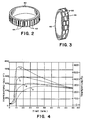
- Ablative bushing 40 is illustrated in Figure 2 wherein the bushing includes a plurality of axial grooves 42 and opposite axial edges of the bushing may include beveled portions 44.
- Bushing 40 comprises an ablative metallic material having a modulus of at least 1x10⁶ psi (7x10⁹ N/m2) and thus provides a much more stable brake configuration from the standpoint of whirl vibration.
- Bushing 40 provides good support stiffness for the brake under normal operating conditions.
- the ablative bushing may comprise a eutectic alloy consisting of 95% Zn and 5% Al, which would provide a melting or flow temperature of approximately 720°F (382°C).
- the particular composition of the ablative bushing may be altered as needed in order to provide a different melting temperature.
- a eutectic bushing compound of 96.5% tin and 3.5% silver would provide a melting temperature of approximately 430°F (221°C).
- low melting temperature alloys or materials which ablate within an appropriate temperature range may be utilized depending on the structure of the brake and position of the ablative bushing.
- Table I below lists example eutectic materials and meltable materials which may be utilized for the ablative bushing of the present invention, according to desired design requirements.
- the materials have a temperature range of approximately 500-1220°F (260-660°C), although this range may be broader if higher or lower temperature materials are desired.
- Figure 3 illustrates an alternative embodiment of the ablative bushing.
- Ablative bushing 46 includes axial grooves 48 which communicate with intermittent circumferentially extending grooves 50. Intermittent circumferentially extending grooves 50 are spaced axially apart from one another. The axial grooves and circumferential grooves would provide storage volume and flow paths for molten eutectic material.
- FIG. 4 and 5 illustrate via the computer simulation the results of RTO stops wherein the brake and axle connections contain a standard prior insulative material bushing and an ablative bushing in accordance with the present invention, respectively.
- Figure 4 illustrates the temperatures experienced by an aircraft brake and axle during a simulated rejected take-off stop wherein a prior standard insulative material bushing was disposed between the torque tube pedestal and a bronze axle bushing located about the axle.
- Curve A illustrates the temperature of the axle during and after the simulated RTO stop.
- Curve B illustrates the temperature of the axle bushing.
- Curve C illustrates the temperature of the insulative bushing made out of typical prior insulative material, and
- Curve D illustrates the temperature of the torque tube pedestal.
- the temperature of the axle should remain below 500°F (288°C) in order to prevent degradation of the cadmium coating.
- a temperature of 550°F (288°C) is deleterious to the axle and may result in the axle having to be replaced, along with the brake, wheel and tire, after an RTO stop.
- Curve A1 represents the axle temperature
- Curve B1 represents the temperature of the bronze axle bushing
- Curve C1 represents the temperature of the ablative bushing made in accordance with the present invention
- Curve D1 represents the temperature of the torque tube pedestal.
- the torque tube pedestal reached a maximum temperature of approximately 1320°F (716°C).
- the ablative bushing reached its maximum temperature of 720°F (382°C) wherein melting of part of the bushing occurred such that air gaps were created between the torque tube pedestal and the axle bushing.
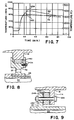
- Figure 6 is a graphic illustration of the temperatures produced according to the total kinetic energy generated during a rejected take-off stop.
- Figure 6 illustrates that approximately 58-60x106 ft-lb (79-87x106 Joules) of kinetic energy is required during an RTO in order to generate a torque tube foot temperature in the range of approximately 720°F (382°C).
- An RTO stop test utilizing an actual aircraft brake, wheel, tire and axle was accomplished utilizing an ablative bushing made out of a eutectic alloy consisting of 95% Zn and 5% Al.
- the eutectic alloy and bushing has a melting temperature of 720°F (382°C).
- the RTO stop comprised a series of preliminary brake stops followed by the full RTO stop.
- the preliminary brake stops comprised three taxi stops at approximately 29 mph (47 km/hr), a landing stop at approximately 134 mph (216 km/hr), three taxi stops again at about 29 mph (47 km/hr), and then a repeat of the afore-described seven stops.
- the results of the preliminary brake stops was that the ablative bushing reached a temperature of approximately 400°F (204°C) during the preliminary brake stop portion of the test (not shown in Figure 7). There was no damage or melting to the ablative bushing during the preliminary brake stop portion of the test.
- the eutectic bushing melted at approximately 720°F (382°C) after the RTO stop, and its effect is illustrated in Figure 7.
- point B2M 720°F or 382°C
- the ablative bushing activated, and the temperature of the bronze axle bushing on curve A2 began to decrease immediately at point A2C.
- the ablative bushing maintained adequate strength and shape up to the melting.
- the molten eutectic alloy fell harmlessly into the wheel well after the RTO stop and the axle was not damaged by the heat of the RTO.
- the ablative bushing tended to ablate or melt in areas of contact with the torque tube pedestal, and the ablative bushing lowered the temperature of the bronze bushing and prevented further heat flow from the torque tube pedestal into the bronze axle bushing and axle.
- FIG. 8 a partial view of an air-craft brake disposed about an axle illustrates an ablative bushing in accordance with the present invention which is disposed radially outwardly of the axle bushing 26.
- Torque tube pedestal 18 is essentially divided into two parts, pedestal 18 and foot 32.
- Foot 32 includes a bolt and flange 34 which provides a seat for ablative bushing 140 and pedestal 18.
- Foot 32 includes access openings 33.
- ablative bushing 140 is disposed radially closer to the carbon heat stack comprising rotors 12 and stators 14, its ablative or melting temperature should be higher so that it will activate at an appropriate temperature.
- Ablative bushing 140 comprises a eutectic material consisting of 88.3% aluminum and 11.7% silicon.
- Ablative bushing 140 will activate at 1070°F (577°C). As the ablative bushing of the present invention is moved radially outwardly and closer to the carbon heat stack, it is necessary to select appropriate compositional materials so that the bushing will activate at a temperature appropriate for its radial position relative to the heat stack and axle.
- a partial section view of an aircraft brake disposed about an axle 30 includes the heat stack of rotors and stators, torque tube pedestal flange 114, and an axle flange 35 secured by a plurality of bolts and nuts 134 to the flange 114.
- an ablative bushing 240 of the present invention Located axially between pedestal flange 114 and axle flange 135 is an ablative bushing 240 of the present invention, bushing 240 having radial grooves 248 and annular intermittent grooves 250.
- the composition of the ablative bushing is selected to be appropriate for its position relative to the heat stack axle so that it will ablate or melt after only a rejected take-off situation.
- the ablative bushing of the present invention may be utilized between the torque tube pedestal and aircraft axle in order to provide adequate support for the torque tube pedestal while also providing a thermal fuse in case of an RTO stop.
- the ablative bushing will ablate, flow, melt, or vaporize at a predetermined temperature so as to introduce ablated or melted away areas that provide air gaps between the torque tube pedestal and axle whereby heat flow from the heat stack through the torque tube pedestal to the axle is significantly reduced. This enables the aircraft axle to be adequately protected so that after an RTO stop the axle need not be replaced.
Landscapes
- Engineering & Computer Science (AREA)
- General Engineering & Computer Science (AREA)
- Mechanical Engineering (AREA)
- Braking Arrangements (AREA)
Claims (10)
- Ablative Buchse mit einer thermischen Sicherung, die einen Wärmeschutz bildet, wobei die Buchse (40,46,140, 240) zum Abstützen eines Bremsmechanismus (10) an der Achse (30) dient und als ringförmige Buchse (40,46,140,240) ausgebildet ist, die eine zentrale Öffnung, um diese herum angeordnete, radial äußere, axial verlaufende Nuten (42,48) und axial äußere, radial verlaufende Nuten (248) aufweist, die beabstandet zueinander angeordnet sind, wobei die Buchse (40,46,140,240) aus einem ablativem Material hergestellt ist, das einen Kompressionsmodul von mindestens 7x10⁹ N/m² hat und das bei einer vorgegebenen Temperatur eine Ablation durchmacht, um einen Luftspalt zu erzeugen, der die Wärmeübertragung auf die Achse (30) verringert.
- Ablative Buchse nach Anspruch 1, bei der die ab-lative Buchse eine eutektische Legierung aus 95% Zn und 5% Al aufweist.
- Ablative Buchse nach Anspruch 1, bei der die ab-lative Temperatur der ablativen Buchse ungefähr 382° C beträgt.
- Ablative Buchse nach Anspruch 1, bei der die ab-lative Buchse eine eutektische Legierung aus 96,5% Zinn und 3,5% Silber aufweist.
- Ablative Buchse nach Anspruch 1, bei der die ab-lative Temperatur der ablativen Buchse (40,46,140,240) ungefähr 577°C beträgt.
- Ablative Buchse nach Anspruch 1 in Verbindung mit dem Bremsmechanismus (10) zum Wärmeschutz der Achse (30), bei der der Bremsmechanismus (10) durch ein Trägerteil (18) abgestützt ist, wobei das Trägerteil (18) eine zentrale Öffnung aufweist, durch die die Achse (30) verläuft, Hülsenmittel (26) oder Flanschmittel (34,35) zwischen der Achse (30) und dem Trägerteil (18) angeordnet sind, und die ablative Buchse (40,46,140,240) zwischen dem Trägerteil (18) und entweder den Hülsenmitteln (26) oder den Flanschmitteln (34,35) angeordnet ist, wobei die ablative Buchse (40,46, 140,240) in der Lage ist, bei einer vorgegebenen Temperatur eine Ablation durchzumachen, um einen Luftspalt zwischen dem Trägerteil (18) und entweder den Hülsenmitteln (26) oder den Flanschmitteln (34,35) zu erzeugen und dadurch die Wärmeübertragung von dem Bremsmechanismus (10) auf die Achse (30) zu verringern.
- Ablative Buchse, Bremsmechanismus und Achse nach Anspruch 6, bei denen das Trägerteil (18) aus einem Befestigungsteil (18) eines Drehmomentrohres besteht, wobei das Befestigungsteil (18) eine radial innere L-förmige Basis (22) und die Hülsenmittel (26) eine komplementäre L-Form haben, so daß die ablative Buchse (40) dazwischen gehalten wird.
- Ablative Buchse, Bremsmechanismus und Achse nach Anspruch 6, bei denen der Bremsmechanismus (10) aus einer Flugzeugbremse und die Achse (30) aus einer Flugzeugachse (30) bestehen.
- Ablative Buchse, Bremsmechanismus und Achse nach Anspruch 6, bei denen das Trägerteil (18) einen Fußabschnitt (32) aufweist, der zwischen der ablativen Buchse (140) und den Hülsenmitteln (26) angeordnet ist, so daß die ablative Buchse (140) radial außerhalb der Hülsenmittel (26) angeordnet ist.
- Ablative Buchse, Bremsmechanismus und Achse nach Anspruch 6, bei denen die Flanschmittel (35) mit dem Trägerteil (18) durch Verbindungsmittel (134) verbunden sind und die ablative Buchse (240) zwischen dem Trägerteil (18) und den Flanschmitteln (135) angeordnet ist.
Applications Claiming Priority (3)
| Application Number | Priority Date | Filing Date | Title |
|---|---|---|---|
| US585415 | 1990-09-19 | ||
| US07/585,415 US5062503A (en) | 1990-09-19 | 1990-09-19 | Ablative brake bushing for axle thermal protection |
| PCT/US1991/006343 WO1992005369A1 (en) | 1990-09-19 | 1991-09-05 | Ablative brake bushing for axle thermal protection |
Publications (2)
| Publication Number | Publication Date |
|---|---|
| EP0548259A1 EP0548259A1 (de) | 1993-06-30 |
| EP0548259B1 true EP0548259B1 (de) | 1994-11-30 |
Family
ID=24341329
Family Applications (1)
| Application Number | Title | Priority Date | Filing Date |
|---|---|---|---|
| EP91917889A Expired - Lifetime EP0548259B1 (de) | 1990-09-19 | 1991-09-05 | Ablative bremsbuchse für achsen-wärmeschutz |
Country Status (6)
| Country | Link |
|---|---|
| US (1) | US5062503A (de) |
| EP (1) | EP0548259B1 (de) |
| JP (1) | JPH0774656B2 (de) |
| CA (1) | CA2090334A1 (de) |
| DE (1) | DE69105516D1 (de) |
| WO (1) | WO1992005369A1 (de) |
Families Citing this family (14)
| Publication number | Priority date | Publication date | Assignee | Title |
|---|---|---|---|---|
| DE4106808A1 (de) * | 1991-03-04 | 1992-09-10 | Bergische Stahlindustrie | Zusammengesetzte bremsscheibe fuer eine teilbelagscheibenbremse |
| DE4303418A1 (de) * | 1992-04-13 | 1993-10-14 | Knorr Bremse Ag | Verfahren zum Herstellen einer Bremsscheibe für eine Scheibenbremse |
| US5402865A (en) * | 1993-07-01 | 1995-04-04 | Alliedsignal Inc. | Aircraft brake assembly retention mechanism |
| US5437352A (en) * | 1993-07-01 | 1995-08-01 | Alliedsignal Inc. | Aircraft brake torque transfer assembly |
| GB9322877D0 (en) * | 1993-11-05 | 1993-12-22 | Dunlop Ltd | Multi-disc brake |
| US5485898A (en) * | 1994-06-22 | 1996-01-23 | Alliedsignal Inc. | Spacer member for aircraft brakes |
| US5494138A (en) * | 1994-10-14 | 1996-02-27 | Alliedsignal, Inc. | Aircraft brake torque transfer assembly |
| US5862890A (en) * | 1996-01-16 | 1999-01-26 | Mcdonnell Douglas Corporation | Restrained aircraft brake apparatus |
| US5819882A (en) * | 1996-04-02 | 1998-10-13 | Alliedsignal Inc. | Multi-disc brake actuator for vibration damping |
| US6581730B1 (en) * | 1999-09-13 | 2003-06-24 | Goodrich Corporation | Aircraft landing gear with integrated brake actuation system |
| US6357561B2 (en) | 1999-10-15 | 2002-03-19 | Stop Technologies Llc | Thermal expansion bushing in a metal matrix composite rotor |
| US10408290B2 (en) * | 2018-02-08 | 2019-09-10 | Goodrich Corporation | Insulated torque plate foot assembly |
| EP4074596B1 (de) | 2021-04-12 | 2023-05-31 | Ratier-Figeac SAS | Bremsscheibe mit integrierter thermischer sicherung und verfahren zur herstellung einer bremsscheibe mit integrierter thermischer sicherung |
| EP4148293B1 (de) * | 2021-09-10 | 2024-12-25 | Ratier-Figeac SAS | Flugzeugbremse mit thermischer sicherung und verfahren zum betrieb |
Family Cites Families (18)
| Publication number | Priority date | Publication date | Assignee | Title |
|---|---|---|---|---|
| US2955677A (en) * | 1958-07-08 | 1960-10-11 | Goodrich Co B F | Wheel and brake |
| DE1167374B (de) * | 1963-02-22 | 1964-04-09 | Knorr Bremse Gmbh | Scheibenbremse fuer Schienenfahrzeugraeder |
| FR1436050A (fr) * | 1965-03-11 | 1966-04-22 | Hispano Suiza Lallemant Soc | Perfectionnements apportés aux freins pour roues d'aviation |
| US3726572A (en) * | 1969-05-14 | 1973-04-10 | Smiths Industries Ltd | Gas-lubricated bearings |
| GB1443709A (en) * | 1972-12-19 | 1976-07-21 | Dunlop Ltd | Disc brakes |
| GB1490743A (en) * | 1974-02-08 | 1977-11-02 | Dunlop Ltd | Wheel and disc brake assembly |
| DE2510640A1 (de) * | 1975-03-12 | 1976-09-23 | Knorr Bremse Gmbh | Bremsscheibe fuer scheibenbremsen von schienenfahrzeugen |
| US3991804A (en) * | 1975-05-02 | 1976-11-16 | The B. F. Goodrich Company | Thermal pressure relief apparatus for tire and rim assembly |
| US4117912A (en) * | 1977-07-18 | 1978-10-03 | The Bendix Corporation | Means for reducing the gap between rotor-backing plate interface during brake depressurization |
| US4195714A (en) * | 1977-08-22 | 1980-04-01 | The Bendix Corporation | Piston and extensible cylinder therefor |
| US4290505A (en) * | 1979-10-29 | 1981-09-22 | Mcdonnell Douglas Corp. | Pin centered brake |
| DE3012420A1 (de) * | 1980-03-29 | 1981-10-15 | Skf Kugellagerfabriken Gmbh, 8720 Schweinfurt | Befestigung einer bremsscheibe an einem fahrzeug |
| DE3024397A1 (de) * | 1980-06-28 | 1982-01-21 | Skf Kugellagerfabriken Gmbh | Waelzlager |
| US4500268A (en) * | 1982-09-30 | 1985-02-19 | Chandler Evans Inc | Rotary pump having brake means with thermal fuse |
| GB2161560B (en) * | 1984-07-13 | 1988-11-09 | Goodrich Co B F | Wheel and brake assembly |
| GB8423956D0 (en) * | 1984-09-21 | 1984-10-31 | Automotive Prod Plc | Caliper disc brake |
| US4875263A (en) * | 1987-02-17 | 1989-10-24 | Nippon Seiko Kabushiki Kaisha | Method of manufacturing a dynamic pressure type slide bearing |
| US4944370A (en) * | 1989-03-27 | 1990-07-31 | Allied-Signal Inc. | Drum drive for use with multiple disc brakes |
-
1990
- 1990-09-19 US US07/585,415 patent/US5062503A/en not_active Expired - Fee Related
-
1991
- 1991-09-05 WO PCT/US1991/006343 patent/WO1992005369A1/en not_active Ceased
- 1991-09-05 EP EP91917889A patent/EP0548259B1/de not_active Expired - Lifetime
- 1991-09-05 CA CA002090334A patent/CA2090334A1/en not_active Abandoned
- 1991-09-05 DE DE69105516T patent/DE69105516D1/de not_active Expired - Lifetime
- 1991-09-05 JP JP3516688A patent/JPH0774656B2/ja not_active Expired - Lifetime
Also Published As
| Publication number | Publication date |
|---|---|
| US5062503A (en) | 1991-11-05 |
| CA2090334A1 (en) | 1992-03-20 |
| JPH0774656B2 (ja) | 1995-08-09 |
| WO1992005369A1 (en) | 1992-04-02 |
| EP0548259A1 (de) | 1993-06-30 |
| DE69105516D1 (de) | 1995-01-12 |
| JPH06501089A (ja) | 1994-01-27 |
Similar Documents
| Publication | Publication Date | Title |
|---|---|---|
| EP0548259B1 (de) | Ablative bremsbuchse für achsen-wärmeschutz | |
| US4979872A (en) | Bearing compartment support | |
| AU686138B2 (en) | Improved energy absorption system | |
| US5083053A (en) | High-friction back-up bearing for magnetic bearings | |
| US6098764A (en) | Shaft brake disk for rail vehicle disk brake systems and method of making same | |
| EP0984197B1 (de) | Verbundwerkstoffschwungrad | |
| JP2004052762A (ja) | 単一のスラストリンクを有する航空機エンジンマウント | |
| JPH0635279B2 (ja) | ロ−タ−翼 | |
| EP3521161B1 (de) | Metallischer hitzeschild mit laminierte folie mit warzen | |
| US20190113092A1 (en) | Shield attachment method and device | |
| US4110056A (en) | Fibre reinforced plastics structure | |
| US20030006655A1 (en) | Heat dispersion, heat dissipation and thermal indication for wheel set assembly | |
| EP4063264B1 (de) | Selbstschmierende elektrisch leitende buchse | |
| EP3524517B1 (de) | Isolierte drehmomentplattenfussanordnung | |
| CA2500986A1 (fr) | Systeme de blocage d'un arbre principal de moteur a palier fusible | |
| US8118562B2 (en) | Sacrificial blade tip | |
| CN107554801B (zh) | 一种桨毂整流罩减振连接结构 | |
| Stanton | New designs for commercial aircraft wheels and brakes. | |
| US10400839B1 (en) | Aircraft brake heat shield | |
| JPH10129481A (ja) | 鉄道車両用ディスクブレーキのアルミ基複合材製ロータ | |
| CN214623018U (zh) | 一种旋转运动部件导热结构 | |
| EP4015234A1 (de) | Hitzeschildanordnung für ein fahrzeugrad | |
| US2909243A (en) | Wheel brake arrangement for aircraft landing gear | |
| CA3040717A1 (en) | Noise reduction fairing | |
| JPS60157906A (ja) | 車両用車輪 |
Legal Events
| Date | Code | Title | Description |
|---|---|---|---|
| PUAI | Public reference made under article 153(3) epc to a published international application that has entered the european phase |
Free format text: ORIGINAL CODE: 0009012 |
|
| 17P | Request for examination filed |
Effective date: 19930305 |
|
| AK | Designated contracting states |
Kind code of ref document: A1 Designated state(s): DE ES FR GB IT |
|
| 17Q | First examination report despatched |
Effective date: 19930903 |
|
| GRAA | (expected) grant |
Free format text: ORIGINAL CODE: 0009210 |
|
| RAP1 | Party data changed (applicant data changed or rights of an application transferred) |
Owner name: ALLIEDSIGNAL INC. |
|
| AK | Designated contracting states |
Kind code of ref document: B1 Designated state(s): DE ES FR GB IT |
|
| PG25 | Lapsed in a contracting state [announced via postgrant information from national office to epo] |
Ref country code: IT Free format text: LAPSE BECAUSE OF FAILURE TO SUBMIT A TRANSLATION OF THE DESCRIPTION OR TO PAY THE FEE WITHIN THE PRE;WARNING: LAPSES OF ITALIAN PATENTS WITH EFFECTIVE DATE BEFORE 2007 MAY HAVE OCCURRED AT ANY TIME BEFORE 2007. THE CORRECT EFFECTIVE DATE MAY BE DIFFERENT FROM THE ONE RECORDED.SCRIBED TIME-LIMIT Effective date: 19941130 Ref country code: ES Free format text: THE PATENT HAS BEEN ANNULLED BY A DECISION OF A NATIONAL AUTHORITY Effective date: 19941130 |
|
| REF | Corresponds to: |
Ref document number: 69105516 Country of ref document: DE Date of ref document: 19950112 |
|
| ET | Fr: translation filed | ||
| PG25 | Lapsed in a contracting state [announced via postgrant information from national office to epo] |
Ref country code: DE Effective date: 19950301 |
|
| PLBE | No opposition filed within time limit |
Free format text: ORIGINAL CODE: 0009261 |
|
| STAA | Information on the status of an ep patent application or granted ep patent |
Free format text: STATUS: NO OPPOSITION FILED WITHIN TIME LIMIT |
|
| 26N | No opposition filed | ||
| REG | Reference to a national code |
Ref country code: FR Ref legal event code: D6 |
|
| REG | Reference to a national code |
Ref country code: GB Ref legal event code: 746 Effective date: 19970516 |
|
| PGFP | Annual fee paid to national office [announced via postgrant information from national office to epo] |
Ref country code: GB Payment date: 19980806 Year of fee payment: 8 |
|
| PGFP | Annual fee paid to national office [announced via postgrant information from national office to epo] |
Ref country code: FR Payment date: 19980902 Year of fee payment: 8 |
|
| PG25 | Lapsed in a contracting state [announced via postgrant information from national office to epo] |
Ref country code: GB Free format text: LAPSE BECAUSE OF NON-PAYMENT OF DUE FEES Effective date: 19990905 |
|
| GBPC | Gb: european patent ceased through non-payment of renewal fee |
Effective date: 19990905 |
|
| PG25 | Lapsed in a contracting state [announced via postgrant information from national office to epo] |
Ref country code: FR Free format text: LAPSE BECAUSE OF NON-PAYMENT OF DUE FEES Effective date: 20000531 |
|
| REG | Reference to a national code |
Ref country code: FR Ref legal event code: ST |
|
| P01 | Opt-out of the competence of the unified patent court (upc) registered |
Effective date: 20230525 |