EP0548057A1 - Fabrication de sachets à infusion - Google Patents
Fabrication de sachets à infusion Download PDFInfo
- Publication number
- EP0548057A1 EP0548057A1 EP93200371A EP93200371A EP0548057A1 EP 0548057 A1 EP0548057 A1 EP 0548057A1 EP 93200371 A EP93200371 A EP 93200371A EP 93200371 A EP93200371 A EP 93200371A EP 0548057 A1 EP0548057 A1 EP 0548057A1
- Authority
- EP
- European Patent Office
- Prior art keywords
- web
- packages
- cutting
- infusion
- rollers
- Prior art date
- Legal status (The legal status is an assumption and is not a legal conclusion. Google has not performed a legal analysis and makes no representation as to the accuracy of the status listed.)
- Granted
Links
Images
Classifications
-
- B—PERFORMING OPERATIONS; TRANSPORTING
- B65—CONVEYING; PACKING; STORING; HANDLING THIN OR FILAMENTARY MATERIAL
- B65B—MACHINES, APPARATUS OR DEVICES FOR, OR METHODS OF, PACKAGING ARTICLES OR MATERIALS; UNPACKING
- B65B9/00—Enclosing successive articles, or quantities of material, e.g. liquids or semiliquids, in flat, folded, or tubular webs of flexible sheet material; Subdividing filled flexible tubes to form packages
- B65B9/02—Enclosing successive articles, or quantities of material between opposed webs
- B65B9/023—Packaging fluent material
-
- B—PERFORMING OPERATIONS; TRANSPORTING
- B65—CONVEYING; PACKING; STORING; HANDLING THIN OR FILAMENTARY MATERIAL
- B65B—MACHINES, APPARATUS OR DEVICES FOR, OR METHODS OF, PACKAGING ARTICLES OR MATERIALS; UNPACKING
- B65B29/00—Packaging of materials presenting special problems
- B65B29/02—Packaging of substances, e.g. tea, which are intended to be infused in the package
- B65B29/025—Packaging of substances, e.g. tea, which are intended to be infused in the package packaging infusion material into pods
Definitions
- the present invention is generally concerned with infusion packages such as tea and coffee bags and similar bags containing herbal or other infusions.
- the invention relates to an apparatus for and a method of manufacturing infusion packages and to a novel form of infusion package made by such apparatus and method.
- a known method and apparatus for producing infusion packages such as tea bags, comprises dosing discrete piles of infusion at spaced intervals onto a rapidly moving paper web, and sealing a second web over the first web to produce a two ply web having a plurality of discrete pockets containing infusion.
- the web is then severed by means of laterally and longitudinally orientated knives into individual packages, or pairs of packages separated by a serrated cut, for discharge or packing.
- infusion packages such as tea and coffee bags which have been mass produced at high production rates for sale on the general market have traditionally been rectangular.
- the invention provides apparatus for manufacturing infusion packages of a predetermined shape, comprising means for dosing infusion in discrete piles onto a first moving web, means synchronised with the dosing means for sealing a second moving web over said first web to produce a travelling two ply web having a plurality of discrete pockets containing infusion, and a web cutting device comprising cooperating co-rotating rollers having recess means adapted to accommodate successive infusion filled pockets and cutting means arranged around said recess means for cutting out each said pocket into a package of predetermined shape, means for removing said cut out packages from the travelling two ply web, and means downstream of the cutting device for collecting the remainder of the web after the packages have been removed.
- the invention provides a method of manufacturing infusion packages of a predetermined shape, comprising the steps of dosing an infusion in discrete piles onto a first moving web, sealing a second moving web over said first web to produce a travelling two ply web having a plurality of discrete pockets containing infusion, and cutting said web into packages having said predetermined shape by passing the web through a roller cutting device having co-operating co-rotating rollers with recess means which accommodate successive infusion filled pockets and cutting means arranged around said recess means for cutting out each said pocket into a package of predetermined shape, removing said cut out packages from the travelling two ply web, and collecting the remainder of the web after the packages have been removed.
- infusion packages such as tea bags can be provided with shapes other than rectilinear.
- the presently preferred packages are substantially round, and a preferred embodiment of the invention has enabled for the first time manufacture of substantially round tea bags at a cost-effective high production rate for sale on the general market place, such tea bags being attractive to the consumer.
- the rollers preferably have a plurality of recesses and corresponding cutting means arranged both circumferentially and in the width direction. This allows a substantial number of packages to be produced per revolution of the rollers.
- the number of cutting means may vary, e.g. 2 to 10 around the circumference and 1 to 5 across the width of a roller.
- the recess means comprises recesses formed on both rollers, and the relative angular orientation of the rollers is such that the or each recess pair on the respective rollers cooperate to form together a recess for accommodating the pockets on the webs, as they pass between the rollers. It is also possible that recesses may be formed only on one of the rollers with the other roller being plain.
- the rollers could act as a rotating punch and die, with cutting edges on both rollers forming a cutting action.
- a cutting edge on one roller could bear on a resilient surface of the other.
- the cutting means is formed by a lip or ridge raised around the recess of one of the rollers (the cutting roller), the lip or ridge co-operating with a hard smooth surface of the opposed roller (anvil roller).
- the lip or ridge defines the predetermined shape of the packages.
- the smooth surface is provided around a recess on the anvil roller.
- the sealing means comprises co-rotating heated rollers through which the webs are passed and which, as with known machines of this type, include raised areas which define the seal areas, the webs including suitable thermoplastic materials for heat sealing.
- the raised areas preferably define a seal shape which matches the predetermined shape of the packages e.g. round. It is envisaged that the sealing means may be combined with the web cutting device by providing the cutting rollers with heating means and raised seals adjacent the cutting means. Clearly, this would provide excellent registration between the cut and the seal. However, a potential drawback with this approach is that the heating of the rollers could be detrimental to the cutting edge of the cutting means which must be high quality to cut material cleanly.
- the cutting rollers and sealing rollers are separate and are synchronised with each other to ensure that the sealed pockets produced by the sealing rollers engage correctly with the cutting rollers so that the cutting may be performed only on the sealed portions of the web leaving a continuously sealed area around the perimeter of the package of predetermined width and controlled tolerance.
- the sealing and cutting rollers have synchronised speeds, with the phase and relative lateral position of the cutting rollers preferably being adjustable with respect to the sealing rollers.
- the seal produced between the webs preferably matches the shape of the final packages.
- a circular seal preferably surrounds each pocket of infusion.
- the whole of the two ply web is effectively converted into packages and no waste web is produced.
- web remaining after the packages have been severed is collected so that the integrity of the web may be maintained before and after the cutting operation.
- the means for collecting the remaining web is effective to maintain a degree of tension in the web downstream of the cutting device whereby the web (which will become waste) surrounding the cut out packages is effective to transport the packages to the package removing means.
- a particularly preferred collecting means comprises a suction system which is advantageously adjustable to provide desired tensioning of the web downstream of the cutting device and which may include a slot like inlet end for receiving the moving web communicating with a conduit for waste removal.
- a roller system has been proposed in place of a suction system.
- the package removing means comprises a reciprocating stamping member or members whose movement is synchronised with the movement of the cutting device, the member or members urging the packages from the moving web, preferably downwardly into a stacking chamber arranged below. From the stacking chamber, the packages may be transferred automatically to cartons or boxes.
- the lower ends of the stamping members which engage the packages are preferably of smaller cross-section than the packages so that the members do not foul on the web material surrounding the packages as the packages are stamped from the web.
- the two ply web preferably is supported by platforms upstream and downstream of the cutting device, the downstream platform being apertured or interrupted beneath the package removing means to permit downward displacement of packages from the moving tensioned web downstream of the cutting device.
- the use of a downstream web support platform itself represents a completely new departure from known apparatus in which all of the web is cut into packages and therefore no web support has been provided downstream of the cutters.
- the dosing means for the infusion may comprise a dosing roller synchronised with the sealing rollers of the preferred embodiment in a known manner.
- the invention extends to an infusion package, such as a substantially round tea or coffee bag, made by the aforesaid method and apparatus.
- a still further aspect of the invention provides a method of manufacturing infusion packages of predetermined shape, comprising dosing infusion in discrete piles onto a first moving web, sealing a second moving web over the first web to produce a travelling two ply web having a plurality of discrete pockets containing infusion, cutting the travelling two ply web into packages having the predetermined shape at a cutting station, the web being fed to a suction waste web removal means downstream of the cutting station, the suction means maintaining tension in the web downstream of the cutting station whereby the web portions surrounding the packages which become waste are effective to transport the packages to a package removal means between the cutting station and waste web removal means.
- the invention extends to apparatus for carrying this aspect of the invention out.
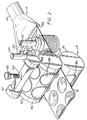
- a web 4 of heat sealable filter paper is fed around a roller 6 of a dosing device (of known type) which deposits discrete piles of tea 7 on the moving web.
- Web 4 and a second moving filter web 5 are then brought together and pass through the nip of heated co-rotating sealing rollers 8, driven in synchronisation with roller 6, which join the strips together to form a two ply web 9 having discrete sealed pockets 3 containing tea.
- This general arrangement is known in the art and will not accordingly be discussed in more detail here.
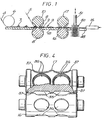
- FIG. 3 shows the heated rollers 8 suitable for use in the present embodiment for producing substantially circular tea bags.
- Each roller 8 is provided with two rows of substantially circular pockets 10 arranged at equispaced intervals around the periphery of the roller. Of course, other numbers or arrangements of pockets would be quite possible.
- the rollers are rotatably carried by suitable bearing means (not shown) and driven via an intermeshing sprocket arrangement 11.
- the raised portions 12 surrounding the pockets 10 pinch the webs 4 and 5 together and by virtue of their heat melt a sealing material, for example polypropylene, provided on the webs to form a two ply web having a plurality of discrete sealed pockets 3 containing tea.
- the operation of the sealing rollers is synchronised (in a known manner) with that of the dosing device 6 so that the tea doses deposited on the web 4 are surrounded by the pockets 10 during the heat sealing.
- the sealing means 8 After the consolidated two ply web 9 leaves the sealing means 8, it passes to a cutting device 13, which will be described in more detail later.
- the cutting device 13 cuts substantially circular bags from the web 9 which will however still surround the bags after they leave the cutting device 13.
- the bags are transported by the web in this manner to a stacking and packing station 14, which will be described in greater detail later in the specification.
- the waste web material is removed by a suction device 15.
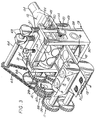
- the cutting device comprises two co-operating, co-rotatable rollers 16, 17.
- the web 9 is fed into the pinch between the rollers along an entry platform 18.
- the roller 17 is supported on a bearing which locates in vertical slots (not shown) running down the length of the opposed limbs 28, 29 of a support housing 30, with the upper roller 17 resting on the lower roller 16 which is carried by a fixed bearing.
- a clamp plate 31 is connected across the top of the limbs 28, 29 and mounts a threaded bolt 32 in a threaded bore.
- This bolt 32 acts via a pressure roller assembly 34 on the cutting rollers 16, 17, so that the contact pressure between the rollers 16, 17 may be raised or lowered by either tightening or loosening the bolt 32.
- the pressure roller assembly comprises rollers 61 at each end which act on the outer portions 62 of the cutting roller 17.
- Both rollers 16, 17 have a plurality of recesses 35, 36 formed in their respective surfaces, in two rows, the recesses in each row being equispaced around the respective roller circumference.
- the recesses are substantially circular in shape and are of approximately the same maximum depth but of somewhat different cross-section. They could be of different depths or shapes depending on the particular shape of bag being produced.
- the recesses 35 on the upper roller 17 are of greater area than those 36 on the lower roller 16 and will thus completely overlie those recesses as the rollers rotate and co-operate. They could instead be of the same area or smaller than those on the lower roller without changing the operational principles.
- the recesses 35, 36 co-operate to provide spaces for accommodating the tea containing portions of the pockets formed in the web 3.
- the number of recesses can vary.
- the illustrated cutting and sealing rollers are of similar diameter, but these may be different with the relative rotation speeds adjusted accordingly.
- a substantially circular cutting edge 37 is formed around each recess 35 on the upper roller which therefore acts as a cutting roller.
- This edge 37 is constituted by a relatively low and narrow raised lip running around the recess. The top of the lip is sufficiently sharp to provide the desired cutting effect as a result of the pressure acting on the lip during cutting by virtue of the contact pressure set by the adjusting bolt 32.
- the cutting edges 37 bear against the smooth surface around the recesses 36 of the lower roller 16 which effectively acts as a rotating anvil. With exactly circular cutting edges the resultant bags may be very slightly elliptical as a result of stretching of the web as it passes through the cutting rollers. This may not be readily noticeable, but could be compensated for by making the cutting edges slightly elliptical if desired.
- the web 9 having discrete sealed pockets containing tea passes successively between the rollers 16, 17.
- the cutting edge 37 acts with the anvil surface on roller 16 to cut out the bag, the space formed between the respective recesses 35 and 36 accommodating the tea containing portion of the bag, as it is cut.
- the speed of rotation of the rollers 16, 17 is linked to that of the sealing rollers 8 by suitable gearing mechanism 38 shown schematically in Figure 3.
- the position of the cutting rollers 16,17 is variable laterally with respect to the sealing rollers 8.
- an adjustment wheel 70 is threadedly engaged in housing arm 28. When the wheel 70 is screwed in or out, the roller 17 moves laterally in the housing 30.
- the relative phase of the sealing rollers 8 and cutting rollers 16,17 may be adjusted by means of a clamping screw in slot arrangement 39 which releaseably interengages a pair of intermediate sprockets 40,41 meshing with the drive sprockets for the respective sets of rollers.
- the tea containing pockets on the web 9 will enter the cutting device correctly with the tea bearing portions accommodated within the recesses 35, 36 of the rollers 16, 17 and the sealed portions extending outwardly thereof to be cut by the cutting edge 37.
- the bags are carried out of the cutting device 13 both by the momentum imparted by the cutting rollers 16, 17 and by the waste web material which still surrounds the bags and is placed in tension by the suction device 15.
- the bags After leaving the cutting means, the bags pass to the stacking station 14.
- This comprises stacking chambers 49 arranged side by side and open at their tops.
- the web in this region is supported by a further platform 48 which is apertured above the stacking chambers.
- stamper members 50 As the bags pass over the tops of the chambers, they are pushed into the chambers by stamper members 50.
- These members which are preferably circular in section and of smaller diameter than the tea bags, are mounted on the end of shafts 51 which reciprocate up and down. If other shaped bags are produced the section of the members preferably matches the bag shape.
- the upper ends of the shafts 51 of the stamper members 50 are resiliently engaged with rotating cam members 63 carried by cam shaft 64 which is coupled to the drive sprocket mechanism 38 via chain drive 65 which engages with a sprocket wheel 66 mounted on the drive shaft of the upper cutting roller 17.
- the reciprocal movement of the stampers may be synchronised with the rotation of the cutting rollers.
- Power drive to the system can be imparted via any one of the drive sprockets of the mechanism 38.
- a waste web removal device 15 Immediately after the stacking station is a waste web removal device 15. This comprises a conduit 54, which tapers to a slot like open mouth 55 at one end, extending across the web travel path and which communicates with a suction device (not shown) at the other end. This allows for an easy and effective removal of waste from the apparatus and, moreover, maintains the tension in the web downstream of the cutting device to provide transport means for the cut out packages as described above.
- the preferred embodiment can achieve a high production rate of bags, for example 1,200 to 2,500 per minute for the "two lane" web illustrated.
- the rollers are all rotated at high speeds, which may vary depending on roller sizes which can also vary. Speeds in the range of 200 to 500 rpm have been used in practice.
Applications Claiming Priority (3)
| Application Number | Priority Date | Filing Date | Title |
|---|---|---|---|
| GB8909846 | 1989-04-28 | ||
| GB898909846A GB8909846D0 (en) | 1989-04-28 | 1989-04-28 | Manufacturing infusion packages |
| EP90905519A EP0422157B2 (fr) | 1989-04-28 | 1990-04-13 | Fabrication d'emballages pour infusions |
Related Parent Applications (2)
| Application Number | Title | Priority Date | Filing Date |
|---|---|---|---|
| EP90905519.6 Division | 1990-04-13 | ||
| EP90905519A Division EP0422157B2 (fr) | 1989-04-28 | 1990-04-13 | Fabrication d'emballages pour infusions |
Publications (2)
| Publication Number | Publication Date |
|---|---|
| EP0548057A1 true EP0548057A1 (fr) | 1993-06-23 |
| EP0548057B1 EP0548057B1 (fr) | 1999-06-30 |
Family
ID=10655951
Family Applications (2)
| Application Number | Title | Priority Date | Filing Date |
|---|---|---|---|
| EP93200371A Expired - Lifetime EP0548057B1 (fr) | 1989-04-28 | 1990-04-13 | Fabrication de sachets à infusion |
| EP90905519A Expired - Lifetime EP0422157B2 (fr) | 1989-04-28 | 1990-04-13 | Fabrication d'emballages pour infusions |
Family Applications After (1)
| Application Number | Title | Priority Date | Filing Date |
|---|---|---|---|
| EP90905519A Expired - Lifetime EP0422157B2 (fr) | 1989-04-28 | 1990-04-13 | Fabrication d'emballages pour infusions |
Country Status (15)
| Country | Link |
|---|---|
| EP (2) | EP0548057B1 (fr) |
| CN (1) | CN1046714A (fr) |
| AT (2) | ATE93798T1 (fr) |
| AU (1) | AU1483995A (fr) |
| CA (1) | CA2031502C (fr) |
| DE (2) | DE69033194T2 (fr) |
| DK (1) | DK0422157T4 (fr) |
| ES (1) | ES2043369T5 (fr) |
| GB (1) | GB8909846D0 (fr) |
| IE (2) | IE950203L (fr) |
| IN (1) | IN177265B (fr) |
| IT (1) | IT1240815B (fr) |
| NZ (1) | NZ233445A (fr) |
| WO (1) | WO1990013487A1 (fr) |
| ZA (1) | ZA903190B (fr) |
Cited By (7)
| Publication number | Priority date | Publication date | Assignee | Title |
|---|---|---|---|---|
| EP0649796A1 (fr) * | 1993-09-24 | 1995-04-26 | JOHNSON & JOHNSON INC. | Emballage pour distribuer une substance de traitement d'un fluide, méthode et dispositif pour sceller à chaud l'emballage distributeur |
| WO1996023695A1 (fr) * | 1995-02-03 | 1996-08-08 | Premier Brands Uk Ltd. | Sachets de the ronds relies et groupes par paires |
| KR960040444A (ko) * | 1995-05-22 | 1996-12-17 | 수다 히데아키 | 시트 포장체의 제조 장치 및 제조 방법 |
| EP0806353A1 (fr) * | 1996-05-09 | 1997-11-12 | I.M.A. INDUSTRIA MACCHINE AUTOMATICHE S.p.A. | Machine pour la fabrication automatisée de sachets d'infusion |
| EP0806352A1 (fr) * | 1996-05-07 | 1997-11-12 | Teepack Spezialmaschinen Gmbh & Co. Kg | Sachet d'infusion à deux compartiments, particulièrement pour thé, et procédé pour sa fabrication |
| GB2314312A (en) * | 1996-06-20 | 1997-12-24 | Ima Spa | Producing joined pairs of infuser bags |
| EP0916476A1 (fr) * | 1997-11-18 | 1999-05-19 | SCHOBER GmbH Werkzeug- und Maschinenbau | Appareil et procédé pour joindre des matériaux filtrants par ultra sons |
Families Citing this family (21)
| Publication number | Priority date | Publication date | Assignee | Title |
|---|---|---|---|---|
| GB2283223B (en) * | 1991-02-14 | 1995-10-11 | Ag Patents Ltd | Tagged infusion packages |
| GB9103156D0 (en) * | 1991-02-14 | 1991-04-03 | Ag Patents Ltd | Manufacturing infusion packages |
| GB9112920D0 (en) * | 1991-06-14 | 1991-08-07 | Premier Brands Uk | Improvements relating to infusion packages |
| GB9307287D0 (en) * | 1993-04-07 | 1993-06-02 | Cambridge Consultants | Improved tabs and manufacture thereof |
| EP0768973B1 (fr) * | 1994-07-01 | 1999-12-29 | Unilever Plc | Production d'articles fa onnes a partir d'une bande |
| GB9422999D0 (en) | 1994-11-15 | 1995-01-04 | Ag Patents Ltd | Method and apparatus for the manufacture of infusion packages |
| IT1280811B1 (it) * | 1995-03-21 | 1998-02-11 | Hitech Systems Srl | Dispositivo per la termosigillatura in continuo di involucri di confezionamento di materiale polimerico termosaldabile e macchine |
| DE19616990C2 (de) * | 1996-04-27 | 2003-01-16 | Bosch Gmbh Robert | Walzensiegelvorrichtung zum Herstellen von Beutelpackungen |
| NL1007171C2 (nl) * | 1997-09-30 | 1999-03-31 | Sara Lee De Nv | Samenstel voor gebruik in een koffiemachine voor het bereiden van koffie, houder en pouch van dat samenstel. |
| DE102004030402B4 (de) * | 2004-03-22 | 2009-08-13 | Reindl, Franz Jun. | Verfahren zum Verpacken von Schüttgut |
| GB2414461B (en) * | 2004-05-24 | 2007-09-12 | Mark Rupert Tucker | Form-fill-seal process |
| MX2007001970A (es) * | 2004-08-19 | 2007-05-09 | Unilever Nv | Empaque mejorado. |
| ITBO20040784A1 (it) * | 2004-12-20 | 2005-03-20 | Ima Spa | Macchina confezionatrice per la realizzazione ed il confezionamento di articoli contenenti prodotti da infusione |
| DE102009008028A1 (de) * | 2009-02-06 | 2010-08-12 | Bayer Schering Pharma Aktiengesellschaft | Verfahren zur Herstellung eines Taschenstapels von zur Aufbewahrung und Bereitstellung von Arzneimittelwafern dienenden Arzneimitteltaschen |
| IT1394271B1 (it) * | 2009-05-25 | 2012-06-06 | Ima Flavour S R L Ora Ima Ind S R L | Gruppo di compressione - incisione - taglio a rulli |
| CN102795355A (zh) * | 2012-08-22 | 2012-11-28 | 大连巨峰包装制品有限公司 | 袋装物料的包装方法 |
| CN107380558A (zh) * | 2017-07-10 | 2017-11-24 | 原秀科技(苏州)有限公司 | 键帽包装机 |
| CN108657538A (zh) * | 2018-06-06 | 2018-10-16 | 舟山市宏基工业产品设计研究所 | 一种塞干燥剂装置 |
| IT201800011153A1 (it) | 2018-12-17 | 2020-06-17 | Azionaria Costruzioni Acma Spa | Dispositivo di trattamento di un nastro continuo |
| CN111003300A (zh) * | 2019-12-12 | 2020-04-14 | 安徽采林间食品有限公司 | 一种食品包装机的自动冲孔切割装置 |
| GB2595934A (en) * | 2020-06-12 | 2021-12-15 | Tata Consumer Products Gb Ltd | Packaging apparatus and method |
Citations (7)
| Publication number | Priority date | Publication date | Assignee | Title |
|---|---|---|---|---|
| GB674886A (en) * | 1949-04-20 | 1952-07-02 | Ivers Lee Co | Improvements in and relating to machines for fabricating packages |
| DE1153673B (de) * | 1960-08-24 | 1963-08-29 | Hesser Ag Maschf | Vorrichtung zum Herstellen von gefuellten Aufgussbeuteln |
| FR1341096A (fr) * | 1962-11-30 | 1963-10-25 | Debell & Richardson | Instrument d'empaquetage et d'agitation pour préparer des boissons |
| GB1128537A (en) * | 1966-10-28 | 1968-09-25 | Hamac Hansella Ag | Apparatus for separating packages from strip material |
| US3736722A (en) * | 1971-07-01 | 1973-06-05 | New Jersey Machine Corp | Packaging machine |
| US3762125A (en) * | 1971-03-17 | 1973-10-02 | Morrell & Co John | Film registration apparatus |
| US4154636A (en) * | 1975-08-27 | 1979-05-15 | Freund Industrial Co., Ltd. | Method of film-coating medicines |
-
1989
- 1989-04-28 GB GB898909846A patent/GB8909846D0/en active Pending
- 1989-04-28 WO PCT/EP1990/000609 patent/WO1990013487A1/fr active IP Right Grant
-
1990
- 1990-04-13 EP EP93200371A patent/EP0548057B1/fr not_active Expired - Lifetime
- 1990-04-13 AT AT90905519T patent/ATE93798T1/de not_active IP Right Cessation
- 1990-04-13 EP EP90905519A patent/EP0422157B2/fr not_active Expired - Lifetime
- 1990-04-13 DK DK90905519T patent/DK0422157T4/da active
- 1990-04-13 ES ES90905519T patent/ES2043369T5/es not_active Expired - Lifetime
- 1990-04-13 AT AT93200371T patent/ATE181707T1/de not_active IP Right Cessation
- 1990-04-13 DE DE69033194T patent/DE69033194T2/de not_active Expired - Fee Related
- 1990-04-13 CA CA002031502A patent/CA2031502C/fr not_active Expired - Fee Related
- 1990-04-13 DE DE69003065T patent/DE69003065T3/de not_active Expired - Fee Related
- 1990-04-20 IN IN391DE1990 patent/IN177265B/en unknown
- 1990-04-26 IE IE950203A patent/IE950203L/xx not_active IP Right Cessation
- 1990-04-26 IE IE148090A patent/IE64933B1/en not_active IP Right Cessation
- 1990-04-26 ZA ZA903190A patent/ZA903190B/xx unknown
- 1990-04-26 NZ NZ233445A patent/NZ233445A/xx unknown
- 1990-04-27 IT IT47893A patent/IT1240815B/it active IP Right Grant
- 1990-04-28 CN CN90102447A patent/CN1046714A/zh active Pending
-
1995
- 1995-03-14 AU AU14839/95A patent/AU1483995A/en not_active Abandoned
Patent Citations (7)
| Publication number | Priority date | Publication date | Assignee | Title |
|---|---|---|---|---|
| GB674886A (en) * | 1949-04-20 | 1952-07-02 | Ivers Lee Co | Improvements in and relating to machines for fabricating packages |
| DE1153673B (de) * | 1960-08-24 | 1963-08-29 | Hesser Ag Maschf | Vorrichtung zum Herstellen von gefuellten Aufgussbeuteln |
| FR1341096A (fr) * | 1962-11-30 | 1963-10-25 | Debell & Richardson | Instrument d'empaquetage et d'agitation pour préparer des boissons |
| GB1128537A (en) * | 1966-10-28 | 1968-09-25 | Hamac Hansella Ag | Apparatus for separating packages from strip material |
| US3762125A (en) * | 1971-03-17 | 1973-10-02 | Morrell & Co John | Film registration apparatus |
| US3736722A (en) * | 1971-07-01 | 1973-06-05 | New Jersey Machine Corp | Packaging machine |
| US4154636A (en) * | 1975-08-27 | 1979-05-15 | Freund Industrial Co., Ltd. | Method of film-coating medicines |
Cited By (8)
| Publication number | Priority date | Publication date | Assignee | Title |
|---|---|---|---|---|
| EP0649796A1 (fr) * | 1993-09-24 | 1995-04-26 | JOHNSON & JOHNSON INC. | Emballage pour distribuer une substance de traitement d'un fluide, méthode et dispositif pour sceller à chaud l'emballage distributeur |
| WO1996023695A1 (fr) * | 1995-02-03 | 1996-08-08 | Premier Brands Uk Ltd. | Sachets de the ronds relies et groupes par paires |
| KR960040444A (ko) * | 1995-05-22 | 1996-12-17 | 수다 히데아키 | 시트 포장체의 제조 장치 및 제조 방법 |
| EP0806352A1 (fr) * | 1996-05-07 | 1997-11-12 | Teepack Spezialmaschinen Gmbh & Co. Kg | Sachet d'infusion à deux compartiments, particulièrement pour thé, et procédé pour sa fabrication |
| EP0806353A1 (fr) * | 1996-05-09 | 1997-11-12 | I.M.A. INDUSTRIA MACCHINE AUTOMATICHE S.p.A. | Machine pour la fabrication automatisée de sachets d'infusion |
| GB2314312A (en) * | 1996-06-20 | 1997-12-24 | Ima Spa | Producing joined pairs of infuser bags |
| GB2314312B (en) * | 1996-06-20 | 2000-03-22 | Ima Spa | Improvement to a machine for the manufacture of filter bags containing infusionable substances, and a relative method of fashioning such bags |
| EP0916476A1 (fr) * | 1997-11-18 | 1999-05-19 | SCHOBER GmbH Werkzeug- und Maschinenbau | Appareil et procédé pour joindre des matériaux filtrants par ultra sons |
Also Published As
| Publication number | Publication date |
|---|---|
| AU618893B2 (en) | 1992-01-09 |
| CA2031502A1 (fr) | 1990-10-29 |
| IN177265B (fr) | 1996-12-21 |
| CN1046714A (zh) | 1990-11-07 |
| EP0422157B2 (fr) | 1998-03-11 |
| ES2043369T3 (es) | 1993-12-16 |
| DE69003065T3 (de) | 1998-08-20 |
| EP0422157A1 (fr) | 1991-04-17 |
| GB8909846D0 (en) | 1989-06-14 |
| DK0422157T3 (da) | 1994-01-10 |
| ZA903190B (en) | 1991-12-24 |
| WO1990013487A1 (fr) | 1990-11-15 |
| AU1483995A (en) | 1995-05-18 |
| IT9047893A0 (it) | 1990-04-27 |
| IT9047893A1 (it) | 1991-10-27 |
| DE69033194T2 (de) | 1999-10-28 |
| ES2043369T5 (es) | 1998-05-16 |
| IE64933B1 (en) | 1995-09-20 |
| CA2031502C (fr) | 1998-03-24 |
| DE69033194D1 (de) | 1999-08-05 |
| ATE93798T1 (de) | 1993-09-15 |
| DE69003065D1 (de) | 1993-10-07 |
| DK0422157T4 (da) | 1998-10-19 |
| EP0422157B1 (fr) | 1993-09-01 |
| DE69003065T2 (de) | 1993-12-16 |
| IT1240815B (it) | 1993-12-17 |
| EP0548057B1 (fr) | 1999-06-30 |
| IE950203L (en) | 1990-10-28 |
| ATE181707T1 (de) | 1999-07-15 |
| AU5406990A (en) | 1990-11-29 |
| NZ233445A (en) | 1993-01-27 |
Similar Documents
| Publication | Publication Date | Title |
|---|---|---|
| EP0548057B1 (fr) | Fabrication de sachets à infusion | |
| US5459980A (en) | Manufacturing infusion packages | |
| US5233813A (en) | Manufacturing infusion packages | |
| EP0310306B1 (fr) | Machine de formage, remplissage et scellage pour la fabrication automatique d'emballages scellés | |
| US5460844A (en) | Method and apparatus for manufacturing infusion packages | |
| US5722217A (en) | Method and apparatus for continuosusly forming, filling and sealing packages while linked together | |
| CA2006747C (fr) | Methode et appareil de fabrication et d'emballage d'ensembles filtrants a utiliser dans un panier de brassage | |
| US4329830A (en) | Method and apparatus for packaging powdery or particle-size material | |
| EP0071584B1 (fr) | Dispositif pour la mise en boîtes automatique de sachets sous étuis | |
| US5466474A (en) | Method and apparatus for manufacturing infusion packages | |
| AU618893C (en) | Manufacturing infusion packages | |
| FR2561206A1 (fr) | Procede et appareil equipant une machine de production a marche rapide pour la fabrication d'articles d'hygiene, notamment de garnitures periodiques, protege-slips ou objets analogues | |
| CN114531867B (zh) | 改进的密封装置 | |
| DE2545739A1 (de) | Verfahren zur herstellung von verpackungen und maschine zur durchfuehrung des verfahrens | |
| JP2004026207A (ja) | 解袋機 | |
| EP0980829A1 (fr) | Procédé et appareillage pour former, remplir et sceller de manière continue des emballages tout en les maintenant reliés l'un à l'autre | |
| FR2641253A1 (fr) | Machine pour la realisation de sachets-doses | |
| MX2007008090A (en) | Container seals | |
| WO1988008394A1 (fr) | Mecanisme de decoupage pour materiau en bande |
Legal Events
| Date | Code | Title | Description |
|---|---|---|---|
| PUAI | Public reference made under article 153(3) epc to a published international application that has entered the european phase |
Free format text: ORIGINAL CODE: 0009012 |
|
| AC | Divisional application: reference to earlier application |
Ref document number: 422157 Country of ref document: EP |
|
| AK | Designated contracting states |
Kind code of ref document: A1 Designated state(s): AT BE CH DE DK ES FR GB IT LI LU NL SE |
|
| 17P | Request for examination filed |
Effective date: 19931204 |
|
| 17Q | First examination report despatched |
Effective date: 19941213 |
|
| 111L | Licence recorded |
Free format text: 0100 IMA INDUSTRIE MACCHINE AUTOMATICHE S.P.A. |
|
| GRAG | Despatch of communication of intention to grant |
Free format text: ORIGINAL CODE: EPIDOS AGRA |
|
| RAP1 | Party data changed (applicant data changed or rights of an application transferred) |
Owner name: TETLEY GB LIMITED |
|
| GRAG | Despatch of communication of intention to grant |
Free format text: ORIGINAL CODE: EPIDOS AGRA |
|
| GRAH | Despatch of communication of intention to grant a patent |
Free format text: ORIGINAL CODE: EPIDOS IGRA |
|
| GRAH | Despatch of communication of intention to grant a patent |
Free format text: ORIGINAL CODE: EPIDOS IGRA |
|
| GRAA | (expected) grant |
Free format text: ORIGINAL CODE: 0009210 |
|
| AC | Divisional application: reference to earlier application |
Ref document number: 422157 Country of ref document: EP |
|
| AK | Designated contracting states |
Kind code of ref document: B1 Designated state(s): AT BE CH DE DK ES FR GB IT LI LU NL SE |
|
| PG25 | Lapsed in a contracting state [announced via postgrant information from national office to epo] |
Ref country code: SE Free format text: THE PATENT HAS BEEN ANNULLED BY A DECISION OF A NATIONAL AUTHORITY Effective date: 19990630 Ref country code: NL Free format text: LAPSE BECAUSE OF FAILURE TO SUBMIT A TRANSLATION OF THE DESCRIPTION OR TO PAY THE FEE WITHIN THE PRESCRIBED TIME-LIMIT Effective date: 19990630 Ref country code: LI Free format text: LAPSE BECAUSE OF FAILURE TO SUBMIT A TRANSLATION OF THE DESCRIPTION OR TO PAY THE FEE WITHIN THE PRESCRIBED TIME-LIMIT Effective date: 19990630 Ref country code: FR Free format text: LAPSE BECAUSE OF FAILURE TO SUBMIT A TRANSLATION OF THE DESCRIPTION OR TO PAY THE FEE WITHIN THE PRESCRIBED TIME-LIMIT Effective date: 19990630 Ref country code: ES Free format text: THE PATENT HAS BEEN ANNULLED BY A DECISION OF A NATIONAL AUTHORITY Effective date: 19990630 Ref country code: CH Free format text: LAPSE BECAUSE OF FAILURE TO SUBMIT A TRANSLATION OF THE DESCRIPTION OR TO PAY THE FEE WITHIN THE PRESCRIBED TIME-LIMIT Effective date: 19990630 Ref country code: BE Free format text: LAPSE BECAUSE OF FAILURE TO SUBMIT A TRANSLATION OF THE DESCRIPTION OR TO PAY THE FEE WITHIN THE PRESCRIBED TIME-LIMIT Effective date: 19990630 Ref country code: AT Free format text: LAPSE BECAUSE OF FAILURE TO SUBMIT A TRANSLATION OF THE DESCRIPTION OR TO PAY THE FEE WITHIN THE PRESCRIBED TIME-LIMIT Effective date: 19990630 |
|
| REF | Corresponds to: |
Ref document number: 181707 Country of ref document: AT Date of ref document: 19990715 Kind code of ref document: T |
|
| REG | Reference to a national code |
Ref country code: CH Ref legal event code: EP |
|
| REF | Corresponds to: |
Ref document number: 69033194 Country of ref document: DE Date of ref document: 19990805 |
|
| ITF | It: translation for a ep patent filed |
Owner name: SOCIETA' ITALIANA BREVETTI S.P.A. |
|
| PG25 | Lapsed in a contracting state [announced via postgrant information from national office to epo] |
Ref country code: DK Free format text: LAPSE BECAUSE OF FAILURE TO SUBMIT A TRANSLATION OF THE DESCRIPTION OR TO PAY THE FEE WITHIN THE PRESCRIBED TIME-LIMIT Effective date: 19990930 |
|
| EN | Fr: translation not filed | ||
| NLV1 | Nl: lapsed or annulled due to failure to fulfill the requirements of art. 29p and 29m of the patents act | ||
| REG | Reference to a national code |
Ref country code: CH Ref legal event code: PL |
|
| PG25 | Lapsed in a contracting state [announced via postgrant information from national office to epo] |
Ref country code: LU Free format text: LAPSE BECAUSE OF NON-PAYMENT OF DUE FEES Effective date: 20000413 |
|
| PLBE | No opposition filed within time limit |
Free format text: ORIGINAL CODE: 0009261 |
|
| STAA | Information on the status of an ep patent application or granted ep patent |
Free format text: STATUS: NO OPPOSITION FILED WITHIN TIME LIMIT |
|
| 26N | No opposition filed | ||
| PG25 | Lapsed in a contracting state [announced via postgrant information from national office to epo] |
Ref country code: DE Free format text: LAPSE BECAUSE OF NON-PAYMENT OF DUE FEES Effective date: 20010201 |
|
| REG | Reference to a national code |
Ref country code: GB Ref legal event code: IF02 |
|
| REG | Reference to a national code |
Ref country code: GB Ref legal event code: 732E |
|
| REG | Reference to a national code |
Ref country code: GB Ref legal event code: 732E |
|
| PGFP | Annual fee paid to national office [announced via postgrant information from national office to epo] |
Ref country code: IT Payment date: 20090403 Year of fee payment: 20 |
|
| PGFP | Annual fee paid to national office [announced via postgrant information from national office to epo] |
Ref country code: GB Payment date: 20090403 Year of fee payment: 20 |
|
| REG | Reference to a national code |
Ref country code: GB Ref legal event code: PE20 Expiry date: 20100412 |
|
| PG25 | Lapsed in a contracting state [announced via postgrant information from national office to epo] |
Ref country code: GB Free format text: LAPSE BECAUSE OF EXPIRATION OF PROTECTION Effective date: 20100412 |