EP0546769B1 - Verriegelbare Insufflationsnadel - Google Patents
Verriegelbare Insufflationsnadel Download PDFInfo
- Publication number
- EP0546769B1 EP0546769B1 EP92311062A EP92311062A EP0546769B1 EP 0546769 B1 EP0546769 B1 EP 0546769B1 EP 92311062 A EP92311062 A EP 92311062A EP 92311062 A EP92311062 A EP 92311062A EP 0546769 B1 EP0546769 B1 EP 0546769B1
- Authority
- EP
- European Patent Office
- Prior art keywords
- protector
- cannula
- pneumoneedle
- pawl spring
- locking pawl
- Prior art date
- Legal status (The legal status is an assumption and is not a legal conclusion. Google has not performed a legal analysis and makes no representation as to the accuracy of the status listed.)
- Expired - Lifetime
Links
Images



Classifications
-
- A—HUMAN NECESSITIES
- A61—MEDICAL OR VETERINARY SCIENCE; HYGIENE
- A61B—DIAGNOSIS; SURGERY; IDENTIFICATION
- A61B17/00—Surgical instruments, devices or methods
- A61B17/34—Trocars; Puncturing needles
- A61B17/3494—Trocars; Puncturing needles with safety means for protection against accidental cutting or pricking, e.g. limiting insertion depth, pressure sensors
- A61B17/3496—Protecting sleeves or inner probes; Retractable tips
-
- A—HUMAN NECESSITIES
- A61—MEDICAL OR VETERINARY SCIENCE; HYGIENE
- A61B—DIAGNOSIS; SURGERY; IDENTIFICATION
- A61B17/00—Surgical instruments, devices or methods
- A61B17/34—Trocars; Puncturing needles
- A61B17/3474—Insufflating needles, e.g. Veress needles
-
- A—HUMAN NECESSITIES
- A61—MEDICAL OR VETERINARY SCIENCE; HYGIENE
- A61M—DEVICES FOR INTRODUCING MEDIA INTO, OR ONTO, THE BODY; DEVICES FOR TRANSDUCING BODY MEDIA OR FOR TAKING MEDIA FROM THE BODY; DEVICES FOR PRODUCING OR ENDING SLEEP OR STUPOR
- A61M13/00—Insufflators for therapeutic or disinfectant purposes, i.e. devices for blowing a gas, powder or vapour into the body
- A61M13/003—Blowing gases other than for carrying powders, e.g. for inflating, dilating or rinsing
Definitions
- the present invention relates generally to instruments for piercing tissue prior to laparoscopic surgery and more particularly to pneumoneedles for inflating the abdomen with fluid such as an insufflating gas prior to laparoscopic surgery.
- Such a needle generally comprises a housing having manually engageable surfaces and proximal and distal ends; a stopcock valve located generally adjacent the proximal end of the housing; a needle having an elongate tubular body or lumen, and proximal and distal ends; and an elongate stylet situated generally within the needle lumen and having proximal and distal ends.
- the distal end of the stylet is blunt to restrict damage to tissue such as internal organs; and the distal end of the needle is sharp to pierce tissue.
- the stylet is mounted to afford reciprocating longitudinal movement relative to the needle between a protecting position with the distal end of the stylet extending beyond the distal end of the needle and a retracted position with the distal end of the stylet retracted to expose portions of the sharp distal end of the needle to afford puncture of tissue (e.g. the abdominal wall) by the needle.
- a spring is present to bias the stylet toward the protecting position.
- a saline/vacuum test is conducted to determine whether the needle has actually entered the abdominal cavity.
- the saline/vacuum test comprises filling the barrel portion of the stopcock valve with saline solution (e.g. with a syringe) and then manually grasping the abdomen and lifting to expand the abdominal cavity. If the Veress-needle has entered the abdominal cavity, such action will create a vacuum and cause the saline solution to flow through the Veress-needle thereby indicating that the Veress-needle has entered the abdominal cavity.
- Veress-needles Another problem associated with prior art Veress-needles also arises out of the position of the stopcock relative to the housing.
- the Veress-needles shown in U.S. Patent No. 4,808,168 have a stopcock valve located generally adjacent a proximal end of the housing.
- the barrel portion of the stopcock is disposed generally coaxially with the longitudinal axis of the Veress-needle.
- Such a location is believed to provide an inconvenient position for connection to the tubing used for passage of the insufflating gas.
- Prior art safety trocars such as may be seen from WIPO International Publication WO 89/03661 teach the use of a protective shield which is locked over the pointed tip of a trocar obturator at the completion of its piercing function. In the case of such trocars, the pointed tip is locked within a tubular shield. This contrasts with Veress pneumoneedles wherein the needle is tubular and a stylet is extended through the needle to isolate the sharpened edges of the needle.
- a safety pneumoneedle through which the abdomen may be inflated with fluid such as insufflating gas.
- the safety pneumoneedle a) provides a positively locking protector for restricting undesirable tissue or organ damage, and b) provides a stopcock valve disposed in a position which is convenient to use during a saline/vacuum test and which affords a convenient position for connecting the pneumoneedle to a tube for passage of insufflating gas.
- the pneumoneedle comprises a housing having exterior surfaces adapted to be manually grasped, and inner surfaces defining an elongate cavity having a fluid passageway portion.
- the pneumoneedle also comprises a cannula having a sharpened distal end for piercing tissue, a protector having a closed blunt distal end, and means in fluid communication with the fluid passageway portion for affording passage of insufflating gas.
- a means mounts the cannula and protector for relative movement between a protecting position with the blunt distal end of the protector extending beyond the sharp distal end of the cannula to restrict engagement between tissue and the sharp distal end of the cannula, and a retracted position with portions of the sharp distal end of the cannula extending beyond the blunt distal end of the protector to afford puncture of tissue.
- the pneumoneedle also includes a latching means for positively locking the cannula and protector in the protecting position.
- the pneumoneedle further includes release means for releasing the latching means when the cannula and protector are locked in the protecting position to afford relative movement between the cannula and protector.
- the latching mechanism restricts undesirable tissue damage as described below.
- the safety pneumoneedle 10 is a device through which the abdominal cavity of a patient (e.g. human) can be inflated with fluid such as insufflating gas.
- the pneumoneedle 10 comprises an elongate housing 12 having a longitudinal axis A, front 14 and rear 15 ends, and exterior surfaces 16 generally cylindrical about the axis A.
- the housing 12 may be manually grasped in a dart-like fashion. Alternatively the housing 12 may be grasped in a manner similar to that shown in Figure 7 except that the two fingers that are the farthest from the thumb are curled between the housing 12 and the user's palm.
- the housing 12 may be constructed from any suitable material such as, but not limited to, polymers or metals or combinations thereof.
- the housing 12 may be injected molded in several parts (e.g. a base portion and a cap portion) using an ABS plastic/polymer material such as the Cycolac GSM 2679F resin generally available from the General Electric Corporation of Pittsfield, Massachusetts.
- the exterior surfaces 16 of the housing 12 may include a structured surface such as ribs 7 for enhancing manual grasping of the housing 12 in the manner shown, for example, in Figure 7.
- the housing 12 includes inner surfaces 17 defining an elongate cavity extending axially between the front 14 and rear 15 ends of the housing 12.
- the cavity includes a fluid passageway portion 18 adjacent the rear end 15, and an actuator portion 19 adjacent the front end 14.
- the actuator portion 19 preferably has a larger diameter than the fluid passageway portion 18 at the juncture of the portions 18 and 19.
- the inner surface 17 of the housing 12 defines a sealing surface 9 around the fluid passageway portion 18 at the juncture between the portions 18 and 19.
- the housing cavity opens through the exterior surfaces 16 of the housing 12 generally adjacent the front 14 and rear 15 ends of the housing 12.
- the housing 12 also has a fluid conduit 8 (Figure 2) communicating with the fluid passageway portion 18 of the elongate cavity.
- the fluid conduit 8 has an axis A' disposed generally at an angle relative to the longitudinal axis A of the housing 12.
- the fluid conduit 8 opens through the exterior surface 16 of the housing 12 between the front 14 and rear 15 ends of the housing 12 generally near the fluid passageway portion 18.
- Figure 7 illustrates a stopcock valve 70 in fluid communication with the fluid conduit 8.
- the location of the stopcock valve 70 is particularly desirable for some types of procedures.
- a user may conveniently fill the barrel portion of the stopcock valve 70 with saline solution (e.g. with a syringe).
- saline solution e.g. with a syringe.
- the barrel portion of the stopcock valve 70 is generally in a vertical orientation to restrict spillage of saline.
- the location of the stopcock valve 70 is also believed to afford a convenient position and orientation for connecting the pneumoneedle to a tube for passage of insufflating gas.
- the location of the stopcock valve 70 is also believed to be beneficial in minimizing the potential for "kinks" in the tube for passage of insufflating gas.
- the pneumoneedle 10 includes a tubular elongate cannula 20 having an inner surface 21 defining a through passageway, a proximal end sealingly and fixedly attached (e.g. by means of a Prism Instant Adhesive, such as product No.'s 401, 405, 406 or 454 generally available from LOCTITE corporation of Newington, Connecticut) to the rear end 15 of the housing 12.
- the through passageway of the cannula 20 is in fluid communication with the fluid passageway portion 18 of the housing 12.
- the cannula 20 includes a sharpened distal end 22 adapted to puncture or pierce tissue, and a predetermined length between the proximal and distal 22 ends.
- the cannula 20 may comprise any suitable material such as but not limited to Stainless Steel.
- the cannula 20 may comprise ASTM #304W Stainless Steel with an outer diameter of approximately 0.083 inches ( 2.1 millimeters), an inner diameter of approximately 0.067 inches ( 1.7 millimeters), and a length measured from the end 15 of the housing 12 to the distal end 22 of about 12 centimeters.
- the pneumoneedle 10 includes a protector assembly 30 comprising a tubular elongate protector 31 having inner surfaces defining a fluid passageway, an outer surface, a closed blunt distal end 32, and an opposite proximal end 33.
- the blunt distal end 32 may be formed from a different piece than the rest of the protector 31.
- the distal end 32 may be formed from a plastic or polymeric member which is adhesively adhered to the remaining portion of the protector 31.
- the blunt distal end 32 and the rest of the protector 31 may be formed from a single monolithic metal (e.g. Stainless Steel) piece by methods known in the art such as, but not limited to spin welding or mechanical deformation processes.
- the protector 31 has a length between ends 32 and 33 that exceeds the predetermined length of the cannula 20 between the proximal and distal 22 ends of the cannula 20.
- the protector 31 is mounted for longitudinal sliding movement within the passageway of the cannula 20 and has axially spaced proximal 35 and distal 36 fluid apertures extending between the protector's 31 inner and outer surfaces.
- the apertures 35 and 36 open into the protector's 31 passageway adjacent the blunt distal 32 and opposite proximal 33 ends respectively.
- the protector 31 may be constructed from any suitable material such as but not limited to a polymer or a metal.
- the protector 31 may comprise an ASTM #304W Stainless Steel with an inner diameter of approximately 0.053 inches (1.35 millimeters) and an outer diameter of approximately 0.065 inches (1.65 millimeters) and a length of 5.78 inches (14.7 centimeters) measured between the proximal end 33 and the distal end 32.
- the protector 31 may comprise a pair of apertures (not shown) at each of the ends 32 and 33 of the protector 31.
- the protector 31 may include a channel (not shown) which extends from a position generally adjacent one end 33 of the protector 31 to a position generally adjacent the other end 32 of the protector 31.
- the protector assembly 30 includes a carrier 37 fixedly attached (e.g. by means of a Prism Instant Adhesive, such as product No.'s 401, 405, 406 or 454 generally available from LOCTITE corporation of Newington, Connecticut) to the proximal end 33 of the protector 31 and disposed within the actuator portion 19 of the housing cavity.
- the carrier 37 has a sealing flange 38 with a sealing flange surface at the juncture between the protector 31 and the carrier 37 for abutting the sealing surface 9 of the housing 12.
- the carrier 37 has latching members 39 extending axially of the housing cavity toward the front end 14.
- the latching members 39 have a first abutment end surface 40 disposed generally at a right angle with respect to the axis A, and include a camming surface 41 disposed at an acute angle with respect to the axis A adjacent and intersecting the first abutment end surface 40.
- the carrier 37 may be constructed from any suitable material, such as but not limited to, a polymer material such as LEXAN HP1 generally available from the General Electric Corporation of Pittsfield, Massachusetts.
- the carrier 37 may be bonded to the cannula 20 by means well known in the art, such as, for example, by means of a Prism Instant Adhesive, such as product No.'s 401, 405, 406 or 454 generally available from LOCTITE corporation of Newington, Connecticut.
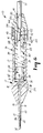
- the protector assembly 30 is axially slidable within the housing cavity relative to the cannula 20 between a protecting position ( Figure 6) with the blunt distal end 32 of the protector 31 extending beyond the sharp distal end 22 of the cannula 20 to restrict engagement between tissue and the sharp distal end 22 of the cannula 20 and a retracted position ( Figure 5).
- the sealing flange 38 has surfaces in sealing engagement with the sealing surface 9 of the housing 12; (2) the distal fluid aperture 36 of the protector 31 is disposed beyond and spaced from the distal end 22 of the cannula 20; (3) the proximal fluid aperture 35 of the protector 31 is disposed within the fluid passageway portion 18 of the housing cavity; and (4) the blunt distal end 32 of the protector 31 extends beyond the sharp distal end 22 of the cannula 20 to restrict engagement between tissue 2 and the sharp distal end 22 of the cannula 20.
- the protector assembly 30 is in the retracted position ( Figure 5)
- portions of the sharp distal end 22 of the cannula 20 extend beyond the distal end 32 of the protector 31 to afford puncture of tissue.
- the pneumoneedle 10 also includes latching and release mechanisms or means for positively locking the protector 31 in the protecting position and for releasing the protector 31 after it has been locked in the protecting position.
- the latching and release means comprise a locking pawl spring 42 disposed within the actuator portion 19 of the housing and fixedly attached (e.g. by mechanically sandwiching the pawl spring 42 between the cap portion of the housing 12 and the rest or base portion of the housing 12, see Figures 3 through 6) at a proximal end to the housing 12.
- the locking pawl spring 42 also has a distal end 43.
- the locking pawl spring 42 may be constructed from any suitable material such as, but not limited to #302 ASTM Stainless Steel.
- the locking pawl spring 42 and at least portions of the housing may be a unitary, monolithic structure constructed from, for example, an injection molded polymer or polycarbonate material such as LEXAN HP1 generally available from the General Electric Corporation of Pittsfield, Massachusetts.
- the locking pawl spring 42 is mounted for movement between a locking position ( Figure 6) and a release position ( Figures 2, 3, 4 and 5).
- a locking position Figure 6
- a release position Figures 2, 3, 4 and 5
- the distal end 43 of the pawl spring 42 engages the first abutment end surface 40 of the latching members 39 to prevent axial movement of the protector 31 relative to the cannula 20 and to lock the protector 31 in the protecting position.
- the distal end 43 of the locking pawl spring 42 is spaced from the first abutment end surface 40 of the latching members 39 to afford relative axial movement between the protector 31 and the cannula 20 to afford piercing of tissue by the sharp end 22 of the cannula 20.
- the locking pawl spring 42 is biased toward the locking position by its own inherent bias.
- the locking pawl spring 42 preferably comprises a monolithic wire member having a pair of base portions 44 extending generally at an angle relative to the longitudinal axis A of the housing cavity, a pair of neck portions 45 extending at an angle relative to the base portions 44 and an end portion extending between the neck portions 45 and having the distal end 43.
- the locking and release means also include a reset button member 50 having an exposed end 51 adapted to be manually pressed, a lock release camming surface 52 disposed at an acute angle with respect to the housing axis A, and a lock release shoulder surface 53 disposed generally at a right angle with respect to the housing axis A and intersecting the lock release camming surface 52.
- the lock release shoulder surface 53 retains the locking pawl spring 42 in the release position until cam surfaces 41 move toward the end 14 of the housing 12 (see Figure 4).
- Portions of the reset button 50 are axially slidable within the actuator portion 19 of the cavity for movement between a latched position ( Figure 6) with the exposed end 51 of the reset button 50 spaced from the front end 14 of the housing 12 and a reset or armed position ( Figures 2 and 3) with the exposed end 51 of the reset button 50 closer to the front end 14 of the housing 12 than in the latched position.
- the pneumoneedle 10 also includes biasing means in the form of a coil spring 60 for biasing the protector assembly 30 toward the protecting position ( Figure 6) and for biasing the reset button member 50 toward the latched position ( Figure 6).
- the carrier 37 comprises a carriage portion 24, the sealing flange 38 and the latching members 39.
- the sealing flange 38 has a surface 28 opposite the sealing surface, and the sealing flange 38 of the carrier 37 includes an elastomeric sealing member 25 constructed from any suitable sealing material such as, but not limited to an elastomer, Buna N rubber or silicone rubber.
- the sealing member 25 may comprise a 2050 LSR silicone seal generally available from Mobay of Rosemont, Illinois.
- the latching members 39 comprise a pair of spaced guide members defining a groove therebetween ( Figures 1 and 2).
- the reset button 50 comprises a body portion 54 having an inner end 55 opposite the exposed end 51, a pair of slots 56 for receiving the guide members (e.g. 39), and a reinforcing rib 57 adapted to be received in the groove 26 between the guide members.
- the sealing flange 38 may include a groove which is adapted to abut a rib (not shown) in the housing 12 for ease of assembly of the product.
- the sealing flange 38 includes flat surfaces which abut flat surfaces on the housing 12 to restrict rotation of the housing protector 31 relative to the housing 12.
- the body portion 54 of the reset button 50 has a notch surface 58 generally adjacent the inner end 55 and an opposite shoulder surface 59 axially spaced from the notch surface 58 and disposed closer to the inner end 55 than the lock release shoulder surface 53.
- the coil spring 60 is situated about the housing axis A and has first 61 and second 62 ends with the first end 61 fixed to the notch surface 58 of the reset button 50 and with the second end 62 fixed to the surface 28 of the sealing flange 38 of the carrier 37 opposite its sealing flange surface.
- the reset button member 50 In the position shown in Figure 3, the reset button member 50 is in the reset or armed position. In this position, the protector 31 is now free to move relative to the cannula 20 to afford piercing of tissue 2 by the cannula 20.
- the reset button member 50, the pawl spring 42, and the protector assembly are in the positions shown in Figure 3, the pneumoneedle is ready to be pressed against the tissue 2 of a patient.
- Figure 4 illustrates the pneumoneedle 10 just after it is initially pressed against tissue 2.
- the protector 31 When the protector 31 is pressed against the tissue 2, the resistance of the tissue 2 will cause the protector assembly 30 to move axially toward the retracted position (e.g. deflect toward front end 14 of housing 12). Such movement of the assembly 30 causes the camming surfaces 41 on the carrier 37 to move the locking pawl spring 42 away from engagement with the lock release shoulder surface 53.
- the reset button member 50 is in a "triggered" position which is between the latched and armed positions. Compare the position of exposed end 51 in Figure 3 (generally the reset or armed position), Figures 4 and 5 (generally the triggered position), and Figure 6 (generally the latched position).
- the protector assembly 30 will deflect and assume generally the position shown in Figure 5.
- the protector assembly 30 will be moved by the spring 60 from the position shown in Figure 5 to the position shown in Figure 6.
- the spring 60 also moves the reset button member 50 to the position shown in Figure 6.
- the present invention has now been described with reference to several embodiments thereof. It will be apparent to those skilled in the art that many changes or additions can be made in the embodiments described without departing from the scope of the present invention.
- the coil spring 60 may be replaced by a suitable biasing means such as a pair of coil springs.
- the scope of the present invention should not be limited to the structures described in this application, but only by structures described by the language of the claims and the equivalents of those structures.
Landscapes
- Health & Medical Sciences (AREA)
- Surgery (AREA)
- Life Sciences & Earth Sciences (AREA)
- Biomedical Technology (AREA)
- Nuclear Medicine, Radiotherapy & Molecular Imaging (AREA)
- Engineering & Computer Science (AREA)
- Pathology (AREA)
- Heart & Thoracic Surgery (AREA)
- Medical Informatics (AREA)
- Molecular Biology (AREA)
- Animal Behavior & Ethology (AREA)
- General Health & Medical Sciences (AREA)
- Public Health (AREA)
- Veterinary Medicine (AREA)
- Infusion, Injection, And Reservoir Apparatuses (AREA)
Claims (17)
- Sicherheits-Pneumonadel (10), durch die der Abdomen mit einem Fluid gefüllt werden kann, wie etwa mit einem Insufflationsgas, wobei die genannte Pneumonadel (10) folgendes umfaßt:ein Gehäuse (12) mit äußeren Oberflächen (16), die manuell gegriffen werden können, und mit inneren Oberflächen (17), die einen elongierten Hohlraum die einem Fluiddurchgangsabschnitt (18) begrenzen;eine Kanüle (20) mit einem scharfen distalen Ende (22) zum Durchdringen von Gewebe;eine Schutzeinrichtung (31) mit einem geschlossenen, stumpfen distalen Ende (32);eine Einrichtung, die sich eine Fluidverbindung mit dem genannten Fluiddurchgangsabschnitt aufweist, um den Durchgang von Insufflationsgas zu ermöglichen; undeine Einrichtung, die die Kanüle (20) und die Schutzeinrichtung (31) so anbringt, daß diese relative zueinander beweglich sind, und zwar zwischen einer Schutzstellung, an der sich das stumpfe distale Ende (32) der Schutzeinrichtung (31) über das scharfe distale Ende (22) der Kanüle (20) hinaus erstreckt, um den Eingriff zwischen dem Gewebe und dem scharfen distalen Ende (22) der Kanüle (20) einzuschränken, und einer eingezogenen Stellung, an der sich Teilstücke des scharfen distalen Endes (22) der Kanüle (20) über das stumpfe distale Ende (32) der Schutzeinrichtung (31) hinaus erstrecken, um eine Gewebepunktion zu ermöglichen;gekennzeichnet durch:eine Verriegelungseinrichtung zur festen Verriegelung der Kanüle (20) und der Schutzeinrichtung an der Schutzstellung.
- Sicherheits-Pneumonadel nach Anspruch 1, ferner mit einer Löseeinrichtung (50) zum Lösen der Verriegelungseinrichtung, wenn die Kanüle (20) und die Schutzeinrichtung (31) an der Schutzstellung verriegelt sind, um eine relative Bewegung zwischen der Kanüle (20) und der Schutzeinrichtung (31) zu ermöglichen.
- Sicherheits-Pneumonadel nach Anspruch 1 oder 2, wobei die Verriegelungseinrichtung eine Nachschlagsicherungsfeder (42) umfaßt, die die Kanüle (20) und die Schutzeinrichtung (31) an der Schutzstellung verriegelt, nachdem die Kanüle (20) das Gewebe eines Patienten durchstochen hat;
wobei die Pneumonadel eine Vorbelastungseinrichtung (60) aufweist, die dazu dient, die Schutzeinrichtung (31) in Richtung der Schutzstellung vorzubelasten, und wobeidie Schutzeinrichtung (31) aufgrund der Widerstandsfähigkeit des Gewebes gegen die Vorbelastung der Vorbelastungseinrichtung (60) in Richtung der eingezogenen Stellung abgelenkt werden kann. - Sicherheits-Pneumonadel nach Anspruch 2 oder 3, wobei die Löseeinrichtung (50) ein Knopfelement (51) aufweist, das relativ zu dem Gehäuse (12) beweglich ist.
- Sicherheits-Pneumonadel nach einem der Ansprüche 1 oder 2, wobei die Pneumonadel ferner eine Vorbelastungseinrichtung (60) aufweist, die dazu dient, die Schutzeinrichtung (31) in Richtung der Schutzstellung vorzubelasten, und wobeidie Schutzeinrichtung (31) aufgrund der Widerstandsfähigkeit des Gewebes gegen die Vorbelastung der Vorbelastungseinrichtung (60) in Richtung der eingezogenen Stellung abgelenkt werden kann.
- Sicherheit-Pneumonadel nach einem der vorstehenden Ansprüche, wobei die Kanüle (20) eine nicht-entfernbare Kanüle umfaßt, die an dem hinteren Ende (15) des Gehäuses (14) dicht und fest angebracht ist.
- Sicherheits-Pneumonadel nach einem der vorstehenden Ansprüche, wobei:das Gehäuse (14) eine Längsachse (A) sowie eine Fluidleitung (8) aufweist, die eine Fluidverbindung mit dem Fluiddurchgangsabschnitt (18) aufweist;wobei die Fluidleitung (8) eine Achse (A') aufweist, die im Verhältnis zu der Längsache (A) des Gehäuses (14) in einem Winkel angeordnet ist, und wobeidie Pneumonadel (10) ferner ein Absperrventil (70) aufweist, das eine Fluidverbindung mit der Fluidleitung (8) aufweist.
- Sicherheits-Pneumonadel nach Anspruch 3, wobei die Schutzeinrichtung proximale (35) und distale (36) Fluidöffnungen umfaßt, die sich zwischen den inneren und äußeren Oberflächen der Schutzeinrichtung (31) erstrecken,
wobei an dem proximalen Ende der Schutzeinrichtung (31) ein Träger (37) fest angebracht ist und sich in dem Gehäuse (12) befindet,
wobei der genannte Träger (37) ein Verriegelungselement (39) mit einer ersten Anstoßendenoberfläche (40) und einer Eingriffsoberfläche (41) aufweist,
wobei die Nachschlagsicherungsfeder (42) ein distales Ende (43) aufweist,
wobei die Nachschlagsicherungsfeder (42) beweglich angebracht ist, und zwar zwischen einer Verriegelungsstellung, an der sich das distale Ende (43) der Nachschlagsicherungsfeder (42) im Eingriff mit der ersten Anstoßendenoberfläche (40) des Trägers (37) befindet, um eine axiale Bewegung der Schutzeinrichtung (31) im Verhältnis zu der Kanüle (20) zu verhindern und um die Schutzeinrichtung (31) an der Schutzstellung zu verriegeln, und einer Freigabestellung, an der das distale Ende (43) der Nachschlagsicherungsfeder (42) einen Abstand zu der ersten Anstoßendenoberfläche (40) des Trägers (37) aufweist, um eine relative axiale Bewegung zwischen der Schutzeinrichtung (31) und der Kanüle (20) zu ermöglichen, so daß die Gewebedurchdringung durch das scharfe Ende (22) der Kanüle (20) ermöglicht wird. - Sicherheits-Pneumonadel nach Anspruch 8, wobei die Nachschlagsicherungsfeder (42) eine Vorbelastung in Richtung der Verriegelungsstellung aufweist.
- Sicherheits-Pneumonadel nach Anspruch 8, ferner mit einer Löseeinrichtung (50) zum Lösen der Verriegelungseinrichtung, wenn die Kanüle (20) und die Schutzeinrichtung (31) an der Schutzstellung verriegelt sind, um eine relative Bewegung zwischen der Kanüle (20) und der Schutzeinrichtung (31) zu ermöglichen,
wobei die Löseeinrichtung einen Auslöseknopf (51) aufweist, der eine Verriegelungsfreigabe-Eingriffsoberfläche (52) und eine Verriegelungsfreigabe-Schulteroberfläche (53) umfaßt,
wobei die Verriegelungsfreigabe-Schulteroberfläche (53) die Nachschlagsicherungsfeder (42) solange an der Freigabestellung hält, bis die Kanüle (20) Gewebe durchdringt. - Sicherheits-Pneumonadel nach Anspruch 10, wobei der Rückstellknopf (51) ein freies Ende aufweist und so angebracht ist, daß er zwischen einer Verriegelungsstellung, an der das freie Ende einen Abstand zu dem Gehäuse (12) aufweist, und einer Rückstellstellung beweglich ist, an der sich das freie Ende näher an dem Gehäuse (12) befindet als an der verriegelten Stellung,
wobei folgendes gilt: wenn sich der genannte Rückstellknopf (51) an der Verriegelungsstellung und die genannte Schutzeinrichtung an der genannten Schutzstellung befinden, bewirkt eine manuelle Bewegung des Rückstellknopfes (51) in Richtung der Rückstellposition, daß die genannte Verriegelungsfreigabe-Eingriffsoberfläche (52) des genannten Rückstellknopfes (51) die genannte Nachschlagsicherungsfeder (42) aus der Verriegelungsstellung in Richtung der Freigabestellung bewegt und es danach ermöglicht, daß die genannte Nachschlagsicherungsfeder (42) mit der genannten Verriegelungsfreigabe-Schulteroberfläche (53) eingreift, um eine relative Bewegung der Schutzeinrichtung zu der Kanüle zu ermöglichen, undwenn die genannte Schutzeinrichtung (31) gegen Gewebe gedrückt wird, sorgt die Widerstandsfähigkeit des Gewebes dafür, daß sich die Schutzeinrichtung (31) axial in Richtung der eingezogenen Stellung bewegt, um eine Gewebedurchdringung zu ermöglichen, und wobei bewirkt wird, daß die genannten Eingriffsoberflächen (41) an dem genannten Träger (37) die genannte Nachschlagsicherungsfeder (42) aus dem Eingriff mit der genannten Verriegelungsfreigabe-Schulteroberfläche (53) lösen, um dadurch eine Bewegung der genannten Nachschlagsicherungsfeder (42) aus der Freigabestellung in Richtung der Verriegelungsstellung zu ermöglichen, wenn die genannte Vorbelastungseinrichtung bewirkt, daß sich die genannte Schutzeinrichtung (31) an die genannte Schutzstellung bewegt, nachdem der Gewebewiderstand durch die Bewegung der Kanüle in die Bauchhöhle eines Patienten freigegeben worden ist. - Sicherheits-Pneumonadel nach Anspruch 11, wobei der genannte Träger (37) einen Trägerabschnitt, einen Dichtungsflansch (38) und ein Verriegelungselement (39) umfaßt;
wobei der genannte Dichtungsflansch (38) eine Oberfläche aufweist, die sich gegenüber der Dichtungsoberfläche (9) des Gehäuses (12) befindet;
wobei das genannte Verriegelungselement (39) ein Paar beabstandeter Führungselemente aufweist, die dazwischen eine Rille begrenzen; und
wobei der genannte Rückstellknopf (51) einen Körperabschnitt umfaßt, der entgegengesetzt zu dem genannten freien Ende ein inneres Ende aufweist, sowie mit einem Schlitzpaar (56) zur Aufnahme der genannten Führungselemente, und mit einer Verstärkungsrippe (57), die zwischen den genannten Führungselementen in der Rille aufgenommen werden kann. - Sicherheits-Pneumonadel nach Anspruch 12, wobei der genannte Körperabschnitt des genannten Rückstellknopfes (51) eine Kerboberfläche aufweist, die allgemein angrenzend an das genannte innere Ende angeordnet ist, und mit einer entgegengesetzten Schulteroberfläche, die axial von der genannten Kerboberfläche beabstandet ist, und die näher an dem genannten inneren Ende angeordnet ist als die genannte Verriegelungsfreigabe-Schulteroberfläche;
wobei die genannte Vorbelastungseinrichtung eine Schraubenfeder aufweist, die um die genannte Gehäuseachse angeordnet ist, und wobei die Feder erste und zweite Enden aufweist, wobei das erste Ende an der genannten Kerboberfläche des genannten Rückstellknopfes (51) angebracht ist, und wobei das genannte zweite Ende an der genannten Oberfläche des genannten Dichtungsflanschs des genannten Trägers angebracht ist, und zwar gegenüber der Dichtungsflanschoberfläche;
wobei das genannte distale Ende der genannten Nachschlagsicherungsfeder nachdem die genannte Eingriffsoberfläche der genannten Schutzeinrichtung die genannte Nachschlagsicherungsfeder aus dem Eingriff mit der Verriegelungsfreigabe-Schulteroberfläche löst, jedoch bevor die genannte Nachschlagsicherungsfeder mit der genannten ersten Anstoßendenoberfläche der genannten Schutzeinrichtung eingreift, mit der genannten entgegengesetzten Schulteroberfläche des genannten Rückstellknopfes eingreift, bis sich die genannte Schutzeinrichtung an die genannte Schutzstellung bewegt. - Sicherheits-Pneumonadel nach Anspruch 2, wobei die genannte Schutzeinrichtung (31) als ein Zusammenbau (30) vorgesehen ist, der ein geschlossenes distales Ende (32), eine erste Anstoßendenoberfläche und eine Eingriffsoberfläche aufweist;
wobei die genannten Verriegelungs- und Löseeinrichtungen eine Nachschlagsicherungsfeder (42) umfassen, die fest an einem proximalen Ende an dem genannten Gehäuse (12) angebracht ist, und mit einem distalen Ende, wobei die genannte Nachschlagsicherungsfeder beweglich angebracht ist, und zwar zwischen einer Verriegelungsstellung, an der sich das distale Ende der Nachschlagsicherungsfeder im Eingriff mit der ersten Anstoßendenoberfläche des Schutzeinrichtungszusammenbaus befindet, um eine axiale Bewegung des Schutzeinrichtungszusammenbaus (30) im Verhältnis zu der Kanüle (20) zu verhindern und um den Schutzeinrichtungszusammenbau an der Schutzstellung zu verriegeln, und einer Freigabestellung, an der das distale Ende der Nachschlagsicherungsfeder einen Abstand zu der ersten Anstoßendenoberfläche des Schutzeinrichtungszusammenbaus (30) aufweist, um eine relative axiale Bewegung zwischen dem Schutzeinrichtungszusammenbau und der Kanüle zu ermöglichen, so daß die Gewebedurchdringung durch das scharfe Ende der Kanüle ermöglicht wird, wobei die genannte Nachschlagsicherungsfeder in Richtung der genannten Verriegelungsstellung vorbelastet ist;mit einem Rückstellknopfelement (50) mit einem freien Ende, das manuell gedrückt werden kann, sowie mit einer Verriegelungsfreigabe-Eingriffsoberfläche und einer Verriegelungsfreigabe-Schulteroberfläche;wobei Teilstücke des genannten Rückstellknopfes innerhalb des genannten Hohlraums verschiebbar beweglich sind, und zwar zwischen einer Verriegelungsstellung, an der das freie Ende des Rückstellknopfs einen Abstand zu dem vorderen Ende des Gehäuses aufweist, und einer Rückstellposition, an der sich das freie Ende des Rückstellknopfes naher als dem vorderen Ende des Gehäuses befindet als an der Verriegelungsstellung;mit einer Vorbelastungseinrichtung (60) zur Vorbelastung des genannten Schutzeinrichtungszusammenbaus in Richtung der genannten Schutzstellung sowie zur Vorbelastung des genannten Rückstellknopfes in Richtung der genannten Verriegelungsstellung;und wobei folgendes gilt: wenn sich der genannte Rückstellknopf an der genannten Verriegelungsstellung befindet, während sich der genannte Schutzeinrichtungszusammenbau an der genannten Schutzstellung befindet, bewirkt eine manuelle Bewegung des genannten Rückstellknopfes in Richtung der genannten Rückstellposition, daß die genannte Verriegelungsfreigabe-Eingriffsoberfläche des genannten Rückstellknopfes die genannte Nachschlagsicherungsfeder aus der genannten Verriegelungsstellung in Richtung der genannten Löse- bzw. Freigabestellung bewegt, und wobei danach ein Eingriff der genannten Nachschlagsicherungsfeder mit der genannten Verriegelungsfreigabe-Schulteroberfläche möglich ist, um eine relative Bewegung des Schutzeinrichtungszusammenbaus zu der Kanüle zu ermöglichen;und wenn das genannte stumpfe Ende (32) des genannten Schutzeinrichtungszusammenbaus (30) danach gegen das Gewebe gedrückt wird, bewirkt der Gewebewiderstand eine axiale Bewegung des Schutzeinrichtungszusammenbaus (30) in Richtung der genannten eingezogenen Stellung, um eine Gewebedurchdringung durch das genannte scharfe Ende der genannten Kanüle zu ermöglichen, und wobei bewirkt wird, daß die genannten Eingriffsoberflächen an dem genannten Schutzeinrichtungszusammenbau die genannte Nachschlagsicherungsfeder aus dem Eingriff mit der genannten Verriegelungsfreigabe-Schulteroberfläche lösen, um dadurch eine Bewegung der genannten Nachschlagsicherungsfeder aus der genannten Lösestellung in Richtung der Verriegelungsstellung zu ermöglichen, wenn die genannte Vorbelastungseinrichtung bewirkt, daß sich der genannte Schutzeinrichtungszusammenbau an die genannte Schutzstellung bewegt, nachdem sich der Gewebewiderstand nach einer Bewegung der Kanüle in die Bauchhöhle gelöst hat. - Pneumonadel nach Anspruch 14, wobei der genannte Hohlraum eine Fluidleitung (8) aufweist, die in einem Winkel relativ zu der Längsachse (A) des genannten Gehäuses (12) angeordnet ist.
- Pneumonadel nach Anspruch 15, wobei der genannte Schutzeinrichtungszusammenbau (30) einen Träger (37) umfaßt, der einen Trägerabschnitt, einen Dichtungsflansch und ein Paar von Verriegelungselementen aufweist;
wobei der genannte Dichtungsflansch eine Dichtungsoberfläche aufweist;
wobei die genannten Dichtungselemente ein Paar beabstandeter Führungselemente umfassen, die dazwischen eine Rille begrenzen;
und wobei der genannte Rückstellknopf einen Körperabschnitt umfaßt, der entgegengesetzt zu dem genannten freien Ende ein inneres Ende aufweist, sowie mit einem Schlitzpaar (56) zur Aufnahme der genannten Führungselemente, und mit einer Verstärkungsrippe (57), die zwischen den genannten Führungselementen in der Rille aufgenommen werden kann. - Sicherheits-Pneumonadel nach Anspruch 16, wobei der genannte genannte Körperabschnitt des genannten Rückstellknopfes eine Kerboberfläche aufweist, die allgemein angrenzend an das genannte innere Ende angeordnet ist, und mit einer entgegengesetzten Schulteroberfläche, die axial von der genannten Kerboberfläche beabstandet ist, und die näher an dem genannten inneren Ende angeordnet ist als die genannte Verriegelungsfreigabe-Schulteroberfläche;
wobei die genannte Vorbelastungseinrichtung (60) eine Schraubenfeder mit ersten und zweiten Enden aufweist, wobei das erste Ende an der genannten Kerboberfläche des genannten Rückstellknopfes angebracht ist, und wobei das genannte zweite Ende an dem genannten Dichtungsflansch angebracht ist,
wobei das genannte distale Ende der genannten Nachschlagsicherungsfeder nachdem die genannte Eingriffsoberfläche des genannten Schutzeinrichtungszusammenbaus (30) die genannte Nachschlagsicherungsfeder (60) aus dem Eingriff mit der Verriegelungsfreigabe-Schulteroberfläche löst, jedoch bevor die genannte Nachschlagsicherungsfeder mit der genannten ersten Anstoßendenoberfläche des genannten Schutzeinrichtungszusammenbaus eingreift, mit der genannten entgegengesetzten Schulteroberfläche des genannten Rückstellknopfes eingreift, bis sich der genannte Schutzeinrichtungszusammenbau (30) an die genannte Schutzstellung bewegt.
Applications Claiming Priority (2)
| Application Number | Priority Date | Filing Date | Title |
|---|---|---|---|
| US80815291A | 1991-12-13 | 1991-12-13 | |
| US808152 | 1991-12-13 |
Publications (3)
| Publication Number | Publication Date |
|---|---|
| EP0546769A2 EP0546769A2 (de) | 1993-06-16 |
| EP0546769A3 EP0546769A3 (en) | 1993-12-22 |
| EP0546769B1 true EP0546769B1 (de) | 1997-03-05 |
Family
ID=25198017
Family Applications (1)
| Application Number | Title | Priority Date | Filing Date |
|---|---|---|---|
| EP92311062A Expired - Lifetime EP0546769B1 (de) | 1991-12-13 | 1992-12-03 | Verriegelbare Insufflationsnadel |
Country Status (5)
| Country | Link |
|---|---|
| US (1) | US5374252A (de) |
| EP (1) | EP0546769B1 (de) |
| JP (1) | JP2547368Y2 (de) |
| AU (1) | AU651745B2 (de) |
| DE (1) | DE69217859T2 (de) |
Cited By (1)
| Publication number | Priority date | Publication date | Assignee | Title |
|---|---|---|---|---|
| WO2013173617A1 (en) * | 2012-05-16 | 2013-11-21 | The Seaberg Company, Inc. | Safety needle |
Families Citing this family (59)
| Publication number | Priority date | Publication date | Assignee | Title |
|---|---|---|---|---|
| US5645557A (en) * | 1990-12-18 | 1997-07-08 | Yoon; Inbae | Safety penetrating instrument with triggered penetrating member retraction and safety member protrusion |
| US5466224A (en) * | 1990-12-18 | 1995-11-14 | Yoon; Inbae | Safety penetrating instrument having a triggered portal sleeve for establishing an endoscopic portal in an anatomical cavity wall |
| US5645556A (en) * | 1990-12-18 | 1997-07-08 | Yoon; Inbae | Safety penetrating instrument with triggered penetrating member retraction and single or multiple safety member protrusion |
| EP0614383A4 (de) * | 1991-11-27 | 1995-04-19 | Inbae Yoon | Zurückziehbares sicherheitspenetrationsinstrument zum einführen einer eingangsmanschette. |
| US5685852A (en) * | 1992-03-30 | 1997-11-11 | Symbiosis Corporation | Needle assembly and methods useful for epidural anesthesia |
| US5405328A (en) * | 1992-06-17 | 1995-04-11 | Minnesota Mining And Manufacturing Company | Trocar with replaceable obturator |
| CA2107852C (en) * | 1992-10-09 | 2004-09-07 | Gerald Leigh Metcalf | Trocar |
| US5346459A (en) * | 1993-04-14 | 1994-09-13 | Minnesota Mining And Manufacturing Company | Trocar |
| US5575804A (en) * | 1993-06-24 | 1996-11-19 | Yoon; Inbae | Safety penetrating instrument with cannula moving during penetration and triggered safety member protrusion |
| US5573545A (en) * | 1993-06-24 | 1996-11-12 | Yoon; Inbae | Safety penetrating instrument with safety member and cannula moving during penetration and triggered cannula and/or safety member protrusion |
| US5569289A (en) * | 1993-06-24 | 1996-10-29 | Yoon; Inbae | Safety penetrating instrument with penetrating member and cannula moving during penetration and triggered safety member protusion |
| US5571134A (en) * | 1993-06-24 | 1996-11-05 | Yoon; Inbae | Safety penetrating instrument with penetrating member and safety member moving during penetration and triggered safety member protrusion |
| US5584848A (en) * | 1993-06-24 | 1996-12-17 | Yoon; Inbae | Safety penetrating instrument with penetrating member, safety member and cannula moving during penetration and triggered safety member protrusion |
| US5607439A (en) * | 1993-06-24 | 1997-03-04 | Yoon; Inbae | Safety penetrating instrument with penetrating member moving during penetration and triggered safety member protrusion |
| US5364365A (en) * | 1993-08-30 | 1994-11-15 | Surgin Surgical Instrumentation, Inc. | Safety device for laparoscopic instruments |
| US5453094A (en) * | 1993-09-17 | 1995-09-26 | Minnesota Mining And Manufacturing Company | Kit assembly for use during a laparoscopic surgical procedure |
| EP0893136B1 (de) * | 1993-12-10 | 2002-09-11 | The BOC Group plc | Venenkanüle |
| WO1996001132A1 (en) * | 1994-07-01 | 1996-01-18 | Northgate Technologies Incorporated | High flow insufflation instrument for laparoscopic surgery |
| US5480389A (en) * | 1994-08-09 | 1996-01-02 | Becton, Dickinson And Company | Method and apparatus for adjusting the length of a combined spinal-epidural needle |
| GB2297256A (en) * | 1995-01-24 | 1996-07-31 | Microsurgical Equipment Ltd | Intra cannula guard for trocar |
| US5779647A (en) | 1995-06-07 | 1998-07-14 | Chau; Sonny | Automated biopsy instruments |
| US5836914A (en) * | 1995-09-15 | 1998-11-17 | Becton Dickinson And Company | Method and apparatus for variably regulating the length of a combined spinal-epidural needle |
| DE69618405T2 (de) * | 1995-09-18 | 2002-08-01 | Becton Dickinson And Co., Franklin Lakes | Nadelschutz mit kollabierender Hülle |
| US5772636A (en) * | 1996-12-02 | 1998-06-30 | Becton Dickinson And Company | Catheter assembly with interlocking telescoping needle shield |
| US6656160B1 (en) * | 1997-04-29 | 2003-12-02 | Applied Medical Resources Corporation | Insufflation needle apparatus |
| DE19726579A1 (de) * | 1997-06-23 | 1999-01-28 | Wisap Gmbh | Insufflationsnadel |
| US5957947A (en) * | 1997-07-18 | 1999-09-28 | Wattiez; Arnaud | Single use trocar assembly |
| US6432098B1 (en) * | 1997-09-04 | 2002-08-13 | The Procter & Gamble Company | Absorbent article fastening device |
| US6033414A (en) * | 1998-06-18 | 2000-03-07 | Cardiac Pacemakers, Inc. | Torque device for left ventricular lead systems |
| USD424194S (en) * | 1998-10-16 | 2000-05-02 | Bio-Plexus, Inc. | Catheter needle assembly |
| MXPA01003878A (es) * | 1998-10-16 | 2002-09-18 | Bio Plexus Inc | Ensamble de seguro de aguja liberable con accesorio opcional de liberacion para el mismo. |
| US6544239B2 (en) | 1998-10-16 | 2003-04-08 | Bio-Plexus Delaware, Inc. | Releasable locking needle assembly with optional release accessory therefor |
| US6146337A (en) * | 1998-11-25 | 2000-11-14 | Bio-Plexus, Inc. | Holder for blood collection needle with blunting mechanism |
| US6733465B1 (en) | 1998-11-25 | 2004-05-11 | Bio-Plexus, Inc. | Holder for blood collection needle with blunting mechanism |
| EP1900333B1 (de) | 2000-08-08 | 2009-10-21 | Tyco Healthcare Group Lp | Geformter Trokarverschluss |
| ES2334841T3 (es) * | 2000-08-08 | 2010-03-16 | Tyco Healthcare Group Lp | Pestillo de trocar moldeado. |
| US6805689B2 (en) | 2001-10-23 | 2004-10-19 | Wei Chen | Safety blood collector device |
| DE10205721A1 (de) * | 2002-02-12 | 2003-08-21 | Biotronik Mess & Therapieg | Führungsdraht und implantierbare Elektrodenleitung |
| WO2005037106A2 (en) * | 2003-10-14 | 2005-04-28 | Suros Surgical Systems, Inc. | Vacuum assisted biopsy needle set |
| US8357103B2 (en) | 2003-10-14 | 2013-01-22 | Suros Surgical Systems, Inc. | Vacuum assisted biopsy needle set |
| US8048003B2 (en) | 2003-10-14 | 2011-11-01 | Suros Surgical Systems, Inc. | Vacuum assisted biopsy device |
| US20050171465A1 (en) * | 2004-02-03 | 2005-08-04 | Smith Robert C. | Pneumoperitoneum needle |
| US20070106300A1 (en) * | 2005-11-08 | 2007-05-10 | Alcon, Inc. | Surgical probe |
| WO2009108794A2 (en) * | 2008-02-26 | 2009-09-03 | Iyunni Venkata Sesha Sayi Nath | Feeding tube |
| JP4806818B2 (ja) * | 2008-11-17 | 2011-11-02 | クリエートメディック株式会社 | トロカール |
| WO2010084869A1 (ja) * | 2009-01-21 | 2010-07-29 | 国立大学法人大阪大学 | 気腹形成および体腔内到達路形成用ガイドチューブシステム |
| US8523817B2 (en) * | 2009-01-23 | 2013-09-03 | Reza S. Mohajer | Veress needle with illuminated guidance and suturing capability |
| US20130324803A1 (en) * | 2009-01-23 | 2013-12-05 | Reza S. Mohajer | Veress needle with illuminated guidance and suturing capability |
| US8608697B2 (en) * | 2010-03-04 | 2013-12-17 | The Board Of Trustees Of The Leland Stanford Junior University | Insertion indicator for needle |
| WO2012145434A1 (en) * | 2011-04-18 | 2012-10-26 | Dr. Py Institute, Llc | Needle with closure and method |
| KR101147564B1 (ko) * | 2012-01-03 | 2012-05-21 | 권혁호 | 펜형 초음파용 미세침 세포 및 조직 검사기 |
| US9757536B2 (en) | 2012-07-17 | 2017-09-12 | Novartis Ag | Soft tip cannula |
| US10064695B2 (en) * | 2013-02-26 | 2018-09-04 | The General Hospital Corporation | Systems for abdominal wall lifting and needle insertion |
| WO2014134624A1 (en) * | 2013-03-01 | 2014-09-04 | The Arizona Board Of Regents On Behalf Of The University Of Arizona | Modified veress needle for tension pneumothorax decompression |
| WO2015038549A2 (en) | 2013-09-11 | 2015-03-19 | Gimmi Gmbh | Endoscopic surgical instruments and related methods |
| US10070873B2 (en) * | 2014-06-30 | 2018-09-11 | Tornier, Inc. | Device for maintaining alignment of a cannulated shaft over a guide pin |
| US9919082B2 (en) * | 2014-07-09 | 2018-03-20 | H&H Medical Corporation | Pneumothorax medical treatment device |
| US11033665B2 (en) | 2016-11-04 | 2021-06-15 | The Arizona Board Of Regents On Behalf Of The University Of Arizona | Modified veress needle assembly for tension pneumothorax decompression |
| NL2027377B1 (en) * | 2021-01-25 | 2022-08-12 | Provinci Sabeair B V | A surgical instrument |
Family Cites Families (71)
| Publication number | Priority date | Publication date | Assignee | Title |
|---|---|---|---|---|
| US1087845A (en) * | 1913-07-16 | 1914-02-17 | James H Stevens | Salvarsan-needle. |
| US1213001A (en) * | 1916-05-02 | 1917-01-16 | Ralph S Philips | Therapeutic apparatus. |
| US1248492A (en) * | 1917-04-10 | 1917-12-04 | A D Haskell | Paracentesis needle or trocar. |
| US1527291A (en) * | 1923-07-09 | 1925-02-24 | Zorraquin Guillermo | Safety-pressure-indicating needle |
| US2001638A (en) * | 1932-11-14 | 1935-05-14 | Res Foundation Inc | Surgical needle |
| DE696957C (de) * | 1939-02-11 | 1940-10-03 | Georg Wolf G M B H | Instrument zum Einfuehren in Koerperhoehlen o. dgl. |
| US2389355A (en) * | 1943-01-27 | 1945-11-20 | Goland | Surgical needle |
| US2496111A (en) * | 1947-09-26 | 1950-01-31 | Turkel Henry | Biopsy needle |
| US2630803A (en) * | 1950-05-12 | 1953-03-10 | Eustachius O Baran | Double pneumothoracic needle |
| US2623521A (en) * | 1951-03-12 | 1952-12-30 | Rose Shaw | Indicating stylet needle |
| GB904635A (en) * | 1960-03-28 | 1962-08-29 | Roderick Sutherland Ross | Hypodermic needle |
| US3454006A (en) * | 1966-01-28 | 1969-07-08 | Weck & Co Inc Edward | Intravenous catheter-needle assembly provided with needle bushing guide |
| US3727613A (en) * | 1970-10-09 | 1973-04-17 | Voys Inc Le | Safety catheter placement assembly |
| US3774604A (en) * | 1971-01-28 | 1973-11-27 | Demeco Medical Products Ab | Infusion cannula assembly |
| US3713447A (en) * | 1971-08-16 | 1973-01-30 | E Adair | Suprapubic shunt |
| DE2544262A1 (de) * | 1975-10-03 | 1977-04-14 | Max Bernhard Ulrich | Intrauterinkatheter |
| US4068659A (en) * | 1976-07-12 | 1978-01-17 | Deseret Pharmaceutical Co., Inc. | Catheter placement assembly |
| US4163446A (en) * | 1978-01-31 | 1979-08-07 | Khosrow Jamshidi | Biopsy needle and removable pad therefor |
| US4190048A (en) * | 1978-07-14 | 1980-02-26 | Metal Bellows Corporation | Infusate injection apparatus |
| SU878265A1 (ru) * | 1979-01-04 | 1981-11-07 | Тернопольский государственный медицинский институт | Способ лапароцентеза |
| US4431426A (en) * | 1979-08-20 | 1984-02-14 | Groshong Leroy E | Methods and apparatus for intravenous therapy and hyperalimentation |
| US4254762A (en) * | 1979-10-23 | 1981-03-10 | Inbae Yoon | Safety endoscope system |
| US4617933A (en) * | 1980-02-19 | 1986-10-21 | Hasson Harrith M | Laparoscope cannula with improved suture receiving means |
| US4922602A (en) * | 1981-03-16 | 1990-05-08 | Creative Research And Manufacturing, Inc. | Method of manufacturing a biopsy needle |
| US4403617A (en) * | 1981-09-08 | 1983-09-13 | Waters Instruments, Inc. | Biopsy needle |
| US4535773A (en) * | 1982-03-26 | 1985-08-20 | Inbae Yoon | Safety puncturing instrument and method |
| GB8316640D0 (en) * | 1983-06-18 | 1983-07-20 | Gill S S | Introducing drainage tubing scopes/instruments into cavities |
| US4609370A (en) * | 1983-06-20 | 1986-09-02 | Morrison Peter C | Surgical needle assembly and apparatus for attachment on a surgical needle assembly |
| US4601710B1 (en) * | 1983-08-24 | 1998-05-05 | United States Surgical Corp | Trocar assembly |
| US4630616A (en) * | 1984-06-15 | 1986-12-23 | Berkley And Company, Inc. | Bone marrow needle |
| SU1435246A1 (ru) * | 1984-11-19 | 1988-11-07 | А. И. Тетюхин и В. Д. Сарычев | Устройство дл пункции и катетеризации |
| US4808168A (en) * | 1986-05-05 | 1989-02-28 | Endotherapeutics | Pneumoneedle |
| US4808170A (en) * | 1985-12-16 | 1989-02-28 | Alcon Laboratories, Inc. | Hypotraumatic injection needle useful in ophthalmic surgery |
| US4627841A (en) * | 1986-02-18 | 1986-12-09 | Dorr Robert T | Infusion needle |
| US4654030A (en) * | 1986-02-24 | 1987-03-31 | Endotherapeutics | Trocar |
| CA1339851E (en) * | 1986-10-17 | 1998-05-05 | Jack R. Lander | Trocar |
| US4902280A (en) * | 1986-10-17 | 1990-02-20 | United States Surgical Corporation | Trocar |
| US4735215A (en) * | 1987-01-05 | 1988-04-05 | Goto David S | Soft tissue biopsy instrument |
| FR2609885B1 (fr) * | 1987-01-22 | 1989-04-14 | Cassou Robert | Instrument pour l'insemination artificielle, le transfert d'embryons ou le prelevement de liquides folliculaires chez les mammiferes |
| US4747831A (en) * | 1987-04-29 | 1988-05-31 | Phase Medical, Inc. | Cannula insertion set with safety retracting needle |
| ES2007667A6 (es) * | 1987-07-28 | 1989-07-01 | Espejo Martinez Antonio | Aparato localizador del espacio epidural |
| US4828547A (en) * | 1987-09-28 | 1989-05-09 | Bio-Plexus, Inc. | Self-blunting needle assembly and device including the same |
| US4858607A (en) * | 1987-10-16 | 1989-08-22 | Pavel Jordan & Associates | Plastic device for injection and obtaining blood samples |
| US4931042A (en) * | 1987-10-26 | 1990-06-05 | Endotherapeutics | Trocar assembly with improved latch |
| WO1989003661A1 (en) * | 1987-10-26 | 1989-05-05 | Endotherapeutics | Trocar assembly with improved latch |
| US4813426A (en) * | 1987-11-09 | 1989-03-21 | Habley Medical Technology Corporation | Shielded safety syringe having a retractable needle |
| US4907599A (en) * | 1988-02-01 | 1990-03-13 | Hart Enterprises, Inc. | Soft tissue core biopsy instrument |
| US4869717A (en) * | 1988-04-25 | 1989-09-26 | Adair Edwin Lloyd | Gas insufflation needle with instrument port |
| GB8816033D0 (en) * | 1988-07-06 | 1988-08-10 | Ethicon Inc | Improved safety trocar |
| US4952207A (en) * | 1988-07-11 | 1990-08-28 | Critikon, Inc. | I.V. catheter with self-locating needle guard |
| US4906236A (en) * | 1988-08-29 | 1990-03-06 | Alberts David S | Self-sheathing hypodermic needle |
| US4973312A (en) * | 1989-05-26 | 1990-11-27 | Andrew Daniel E | Method and system for inserting spinal catheters |
| GB8914728D0 (en) * | 1989-06-27 | 1989-08-16 | Rocket Of London Ltd | A pneumoperitoneal needle |
| US5036860A (en) * | 1989-11-24 | 1991-08-06 | Medical Device Technologies, Inc. | Disposable soft tissue biopsy apparatus |
| US4995866A (en) * | 1989-12-15 | 1991-02-26 | Microvena Corporation | Combined needle and dilator apparatus |
| US5318580A (en) * | 1990-09-11 | 1994-06-07 | Origin Medsystems, Inc. | Retractable trocar |
| US5116353B1 (en) * | 1990-10-05 | 1996-09-10 | Digital Voice Systems Inc | Safety trocar |
| US5226426A (en) * | 1990-12-18 | 1993-07-13 | Inbae Yoon | Safety penetrating instrument |
| US5292310A (en) * | 1990-12-27 | 1994-03-08 | Inbae Yoon | Safety needle |
| US5104382A (en) * | 1991-01-15 | 1992-04-14 | Ethicon, Inc. | Trocar |
| US5152754A (en) * | 1991-02-15 | 1992-10-06 | Minnesota Mining And Manufacturing Company | Trocar |
| US5137509A (en) * | 1991-04-17 | 1992-08-11 | Dexide, Inc. | Surgical insufflation instrument |
| US5295993A (en) * | 1991-04-30 | 1994-03-22 | United States Surgical Corporation | Safety trocar |
| US5098388A (en) * | 1991-05-02 | 1992-03-24 | Richard Kulkashi | Veress needle assembly |
| US5139485A (en) * | 1991-05-03 | 1992-08-18 | Ethicon, Inc. | Verress needle with enhanced acoustical means |
| DE600895T1 (de) * | 1991-08-30 | 1995-04-20 | Origin Medsystems Inc | Trokar mit mehreren adaptern und einem abnehmbaren obturator. |
| DE600921T1 (de) * | 1991-08-30 | 1995-04-20 | Origin Medsystems Inc | Trokar mit zurückziehbarer spitze. |
| AU2589392A (en) * | 1991-08-30 | 1993-04-05 | Origin Medsystems, Inc. | Trocar with retracting tip and palm actuator mechanism |
| US5104381A (en) * | 1991-08-30 | 1992-04-14 | Origin Medsystems, Inc. | Pneumoneedle with removable stylet assembly |
| US5158552A (en) * | 1991-11-04 | 1992-10-27 | American Cyanamid Company | Safety trocar instrument having a retractable trocar actuated by relief of pressure on the trocar point |
| US5226891A (en) * | 1992-04-07 | 1993-07-13 | Applied Medical Resources | Seal protection apparatus |
-
1992
- 1992-11-25 AU AU29647/92A patent/AU651745B2/en not_active Expired
- 1992-12-03 DE DE69217859T patent/DE69217859T2/de not_active Expired - Lifetime
- 1992-12-03 EP EP92311062A patent/EP0546769B1/de not_active Expired - Lifetime
- 1992-12-10 JP JP1992085022U patent/JP2547368Y2/ja not_active Expired - Lifetime
-
1994
- 1994-02-01 US US08/190,235 patent/US5374252A/en not_active Expired - Lifetime
Cited By (1)
| Publication number | Priority date | Publication date | Assignee | Title |
|---|---|---|---|---|
| WO2013173617A1 (en) * | 2012-05-16 | 2013-11-21 | The Seaberg Company, Inc. | Safety needle |
Also Published As
| Publication number | Publication date |
|---|---|
| US5374252A (en) | 1994-12-20 |
| AU651745B2 (en) | 1994-07-28 |
| JP2547368Y2 (ja) | 1997-09-10 |
| DE69217859D1 (de) | 1997-04-10 |
| AU2964792A (en) | 1993-06-17 |
| DE69217859T2 (de) | 1997-08-21 |
| EP0546769A2 (de) | 1993-06-16 |
| EP0546769A3 (en) | 1993-12-22 |
| JPH0558101U (ja) | 1993-08-03 |
Similar Documents
| Publication | Publication Date | Title |
|---|---|---|
| EP0546769B1 (de) | Verriegelbare Insufflationsnadel | |
| US5360405A (en) | Automatic retractable safety penetrating instrument | |
| US5868773A (en) | Shielded trocar with safety locking mechanism | |
| US5578053A (en) | Safety needle instrument having a triggered safety member | |
| US6811545B2 (en) | Safety needle | |
| US5364372A (en) | Trocar and cannula | |
| US5346459A (en) | Trocar | |
| EP0563306B1 (de) | Sicherheitspenetrationsinstrument | |
| US5137509A (en) | Surgical insufflation instrument | |
| US5320610A (en) | Automatic retractable trocar with safety shield and method of use | |
| US5389077A (en) | Minimally invasive body cavity penetrating instruments | |
| US5676156A (en) | Automatic retractable safety penetrating instrument | |
| US5545150A (en) | Trocar | |
| US5284474A (en) | Trochar system for laparoscopy | |
| US5827315A (en) | Safety penetrating instrument with penetrating member protected after penetration to predetermined depth | |
| US20230256207A1 (en) | Iv catheter device | |
| JPH09501855A (ja) | 腹腔鏡用安全装置 | |
| EP0661950A4 (de) | Sich automatisch zurückziehendes sicherheitspenetrationsinstrument. | |
| US20060200182A1 (en) | Safety shielded trocar with oblique incision edges | |
| CN112546338A (zh) | 留置针 |
Legal Events
| Date | Code | Title | Description |
|---|---|---|---|
| PUAI | Public reference made under article 153(3) epc to a published international application that has entered the european phase |
Free format text: ORIGINAL CODE: 0009012 |
|
| AK | Designated contracting states |
Kind code of ref document: A2 Designated state(s): DE FR GB IT |
|
| PUAL | Search report despatched |
Free format text: ORIGINAL CODE: 0009013 |
|
| AK | Designated contracting states |
Kind code of ref document: A3 Designated state(s): DE FR GB IT |
|
| 17P | Request for examination filed |
Effective date: 19940620 |
|
| 17Q | First examination report despatched |
Effective date: 19951110 |
|
| GRAG | Despatch of communication of intention to grant |
Free format text: ORIGINAL CODE: EPIDOS AGRA |
|
| RAP1 | Party data changed (applicant data changed or rights of an application transferred) |
Owner name: ORIGIN MEDSYSTEMS, INC. |
|
| GRAH | Despatch of communication of intention to grant a patent |
Free format text: ORIGINAL CODE: EPIDOS IGRA |
|
| GRAH | Despatch of communication of intention to grant a patent |
Free format text: ORIGINAL CODE: EPIDOS IGRA |
|
| GRAA | (expected) grant |
Free format text: ORIGINAL CODE: 0009210 |
|
| AK | Designated contracting states |
Kind code of ref document: B1 Designated state(s): DE FR GB IT |
|
| REF | Corresponds to: |
Ref document number: 69217859 Country of ref document: DE Date of ref document: 19970410 |
|
| ITF | It: translation for a ep patent filed | ||
| ET | Fr: translation filed | ||
| PLBE | No opposition filed within time limit |
Free format text: ORIGINAL CODE: 0009261 |
|
| 26N | No opposition filed | ||
| REG | Reference to a national code |
Ref country code: GB Ref legal event code: IF02 |
|
| REG | Reference to a national code |
Ref country code: GB Ref legal event code: 732E |
|
| REG | Reference to a national code |
Ref country code: FR Ref legal event code: TP |
|
| REG | Reference to a national code |
Ref country code: FR Ref legal event code: CD Ref country code: FR Ref legal event code: CA |
|
| PGFP | Annual fee paid to national office [announced via postgrant information from national office to epo] |
Ref country code: GB Payment date: 20101229 Year of fee payment: 19 Ref country code: IT Payment date: 20101227 Year of fee payment: 19 |
|
| PGFP | Annual fee paid to national office [announced via postgrant information from national office to epo] |
Ref country code: FR Payment date: 20120104 Year of fee payment: 20 |
|
| PGFP | Annual fee paid to national office [announced via postgrant information from national office to epo] |
Ref country code: DE Payment date: 20111229 Year of fee payment: 20 |
|
| REG | Reference to a national code |
Ref country code: DE Ref legal event code: R071 Ref document number: 69217859 Country of ref document: DE |
|
| REG | Reference to a national code |
Ref country code: DE Ref legal event code: R071 Ref document number: 69217859 Country of ref document: DE |
|
| REG | Reference to a national code |
Ref country code: GB Ref legal event code: PE20 Expiry date: 20121202 |
|
| PG25 | Lapsed in a contracting state [announced via postgrant information from national office to epo] |
Ref country code: GB Free format text: LAPSE BECAUSE OF EXPIRATION OF PROTECTION Effective date: 20121202 |