EP0545127A1 - Machine à laver la vaisselle avec circuit d'alimentation d'eau - Google Patents
Machine à laver la vaisselle avec circuit d'alimentation d'eau Download PDFInfo
- Publication number
- EP0545127A1 EP0545127A1 EP92119523A EP92119523A EP0545127A1 EP 0545127 A1 EP0545127 A1 EP 0545127A1 EP 92119523 A EP92119523 A EP 92119523A EP 92119523 A EP92119523 A EP 92119523A EP 0545127 A1 EP0545127 A1 EP 0545127A1
- Authority
- EP
- European Patent Office
- Prior art keywords
- water
- door
- supply circuit
- water supply
- dishwasher
- Prior art date
- Legal status (The legal status is an assumption and is not a legal conclusion. Google has not performed a legal analysis and makes no representation as to the accuracy of the status listed.)
- Granted
Links
Images
Classifications
-
- A—HUMAN NECESSITIES
- A47—FURNITURE; DOMESTIC ARTICLES OR APPLIANCES; COFFEE MILLS; SPICE MILLS; SUCTION CLEANERS IN GENERAL
- A47L—DOMESTIC WASHING OR CLEANING; SUCTION CLEANERS IN GENERAL
- A47L15/00—Washing or rinsing machines for crockery or tableware
- A47L15/42—Details
- A47L15/4214—Water supply, recirculation or discharge arrangements; Devices therefor
- A47L15/4217—Fittings for water supply, e.g. valves or plumbing means to connect to cold or warm water lines, aquastops
-
- A—HUMAN NECESSITIES
- A47—FURNITURE; DOMESTIC ARTICLES OR APPLIANCES; COFFEE MILLS; SPICE MILLS; SUCTION CLEANERS IN GENERAL
- A47L—DOMESTIC WASHING OR CLEANING; SUCTION CLEANERS IN GENERAL
- A47L15/00—Washing or rinsing machines for crockery or tableware
- A47L15/42—Details
- A47L15/4229—Water softening arrangements
-
- A—HUMAN NECESSITIES
- A47—FURNITURE; DOMESTIC ARTICLES OR APPLIANCES; COFFEE MILLS; SPICE MILLS; SUCTION CLEANERS IN GENERAL
- A47L—DOMESTIC WASHING OR CLEANING; SUCTION CLEANERS IN GENERAL
- A47L15/00—Washing or rinsing machines for crockery or tableware
- A47L15/42—Details
- A47L15/4251—Details of the casing
- A47L15/4257—Details of the loading door
Definitions
- the present invention relates to an automatic dishwashing machine provided with a water supply circuit including a water softener associated with an arrangement suitable to periodically regenerate the water softener.
- a simple and effective water supply circuit of this type is for instance described in EP-B-0 219 704, wherein the regeneration arrangement comprises a reservoir for metering a volume of water which is used to regenerate, through a multi-dose salt container, the ion-exchange resins contained in the water softener.
- the water supply circuit also comprises a solenoid valve to control the amount of water to be fed into the wash tub of the machine, as well as at least a further solenoid valve suitable to control the phases of regeneration of the water softener.
- substantially the entire water supply circuit is usually housed in the hollow space between the wash tub and the non-movable part of the casing of the machine, which is provided with a front access door.
- the water supply circuit is arranged in an area which is hardly accessible for mounting and adjusting the various components, and for possible maintenance or servicing purposes, as well.
- the salt container in particular, is commonly arranged in the bottom part of the machine and is only accessible, for periodical refill operations, after having drawn the lower crockery support rack out of the wash tub.
- a dishwasher is also known, for instance from DE-A-1 800 092, which is provided with a single-dose salt container directly connected with the water supply circuit, upstream of the water softener, and arranged within the access door of the machine.
- a single-dose salt container directly connected with the water supply circuit, upstream of the water softener, and arranged within the access door of the machine.
- tap water flows through the supply circuit, part of it fills the salt container, thereby forming brine which flows back by gravity to enter the water softener upon termination of the water supply phase.
- the salt container undesirably must be filled by the user with a proper amount of salt before starting each operating cycle.
- the salt container housed in the access door is connected to the water supply circuit through a hydraulic rotary joint, or the like, which is provided in correspondence of the hinge of the door and undesirably complicates the structure of the dishwasher.
- DE-U-8 511 185 describes an automatic dishwasher in which both the water softener and the salt container are housed within the access door of the machine and can mutually communicate through a controlled valve which undesirably requires proper wiring in correspondence of the door, which wiring brings about the electrical insulation problems mentioned above.
- the water softener is connected with the remaining part of the water supply circuit of the dishwasher through flexible pipes which are subject to ruptures after a number of openings and closings of the door.
- this prior art dishwasher suffers from the drawback that the amount of brine which regenerates the water softener, being time-controlled through actuation of the controlled valve, can undesirably vary according to pressure changes in the water mains.
- a dishwasher with a water supply circuit of the type including a metering reservoir for the regeneration water, which not only is simple and readily accessible, but also very compact, effective and reliable in operation.
- Another scope of this invention is to provide a dishwasher of the above-mentioned type wherein the wirings associated with the water supply circuit are substantially reduced and thereby safe with regard to electrical insulation.
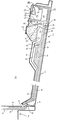
- the dishwasher comprises a casing 1 (only the bottom part of which is shown, for the sake of simplicity) housing a wash tub 2 which is accessible through a front door 3 hinged at the bottom on the machine, at 4.
- the door 3 is of the double-wall kind, with an outer wall 5 and an inner wall 6, the latter forming a portion of the wash tub 2 when the door is closed, in a substantially vertical position.
- the dishwasher is equipped with a water supply circuit of the type including a water softener 7 and a metering reservoir 8 for water suitable to cyclically regenerate the water softener 7 through a multi-dose salt container 9.
- a portion of the water supply circuit including not only the salt container 9, but also the metering reservoir 8, is housed inside the access door 3, in the hollow space between the walls 5 and 6.
- said portion of the water supply circuit additionally includes the water softener 7.
- the water supply circuit comprises a feeding conduit 10 connected with the water mains through at least a valve 11 which is controlled by the programmer (not shown) of the machine and is preferably arranged in correspondence of a non-movable part of the casing of the machine.
- the conduit 10 Downstream from the valve 11, the conduit 10 extends into the door 3 upwards (with respect to the vertical closed position of the door) to communicate with the inlet 12 of the water softener 7 through an air-break 13.
- a portion 14 of the conduit 10 extending between the air-break 13 and the water softener 7 has a labyrinth-shaped configuration.
- the outlet 15 of the water softener 7 is connected with a conduit 16 which preferably extends towards the bottom of the dishwasher, as shown in the figure, where it is intended to communicate with the wash tub 2.
- the portions of the conduits 10 and 16 which are housed inside the door 3 are connected with the portions of the conduits 10 and 16 which are housed in the non-movable part of the casing 1 through relevant break-away coupling means 17 and 18, respectively, which are arranged to break away when the door is opened as shown in the figure.
- the break-away coupling means 17, 18 are located in correspondence of the bottom of the access door 3 and are for example of the simple male-female fitting type, or of the kind including a flexible water-tight seal.
- the air-break 13 is provided in the conduit 10 between a nozzle 19 and a diffuser 20 capable of recovering hydraulic pressure.
- the inlet mouth of the diffuser 20 is formed at the bottom of a funnel-shaped collecting element 21 having an overflow device 22. When the door 3 is substantially closed the collecting element 21 lies above the water softener 7 and is in communication with the tub 2 through the overflow device 22 and a channel 23 provided in the access door.
- the conduit 10 Upstream of the air-break 13, the conduit 10 is provided with a branch pipe 24 having a calibrated cross-section and communicating with a first chamber 25 of the metering reservoir 8.
- the first chamber 25 is suitable to communicate with the tub 2 through an overflow wall 26 and an aperture 27 of the door 3.
- the overflow wall 26 determines the water volume which can be collected in the chamber 25 to regenerate the water softener 7, which is lying at a lower level, as it will be described hereinafter.
- Such a water volume is adjustable, in a per se known manner, by means of a mass 28 whose level in the chamber 25 can be changed by acting on a knob 29. This latter is arranged outside the door 3 and is sealingly connected to the mass 28; hence, the volume of the regeneration water can be readily adjusted after having opened the access door 3.
- the metering reservoir 8 also comprises a second chamber 30 which, when the door 3 is in a substantially horizontal open position, is laying below the first chamber 25 and is capable of communicating therewith through a siphon device 31.
- the latter is preferably arranged at the top of chamber 25 (with the door 3 in the closed position).
- the bottom of the second chamber 30 communicates with the subjacent salt container 9 (with the door 3 in the closed position) through a channel 32 that is preferably provided with a thermostatic valve 33.
- the valve 33 is responsive to the temperature of the environment adjacent to the inner wall 6 of the access door and is arranged to open and close, respectively, when such a temperature is respectively lower and higher than a predetermined value (40° C, for instance).
- the thermostatic valve 33 may be for example of the bimetal type, or the like.
- the salt container 9 has a loading aperture which is provided with a removable cap 34 and is accessible from the exterior of the door 3, preferably through the inner wall 6. Hence, even the periodical operations to refill the salt container 9 may be readily performed by opening the door of the dishwasher and removing the cap 34.
- the outlet 35 of the salt container 9 is preferably adjacent to to the inner wall 6 of the access door and is arranged to communicate with the water softener 7 through a pipe 36 having a calibrated cross-section and terminating with an outlet mouth adjacent to the collecting element 21.
- a pipe 36 having a calibrated cross-section and terminating with an outlet mouth adjacent to the collecting element 21.
- the outlet mouth of pipe 36 is laying over the collecting element 21, into which brine can be delivered therefrom.
- the coupling means 17, 18 are joined together and the tub 2 can be fed with tap water by opening the valve 11.
- the tap water flows along the conduit 10, passes through the air-break 13, is softened in the water softener 7 and enters the wash tub 2 through the conduit 16.
- Possible water leakages in correspondence of the air-break 13 are conveyed into the tub 2 via the overflow device 22 and channel 23.
- a proportion of the tap water enters through the branch pipe 24 into the chamber 25, where it is metered by means of the overflow wall 26; possible exceeding water falls into the wash tub through the aperture 27.
- valve 11 After termination of an operative cycle of the dishwasher, the valve 11 is closed and the access door 3 is completely opened (in a substantially horizontal position) to withdraw the support racks (not shown) out of the tub 2 and remove the crockery therefrom.
- the water contained in the chamber 25 of the metering reservoir 8 flows into the subjacent chamber 30 through the siphon device 31, which is properly sized to this aim.
- the opening of the door 3 also promotes cooling down of the temperature sensor of the thermostatic valve 33.
- the valve 33 is therefore open, or it opens within short, according to the different temperature conditions.
- the metered amount of water contained in the chamber 30 of the reservoir 8 flows by gravity along the channel 32 and enters the salt container 9, from which the so formed brine is delivered through the calibrated pipe 36 to fall with a reduced flow into the subjacent collecting element 21.
- the brine slowly enters the conduit 10 through the diffuser 20 and flows to the water softener 7, from which the water formerly contained is conveyed to the bottom of the tub 2 via the conduit 16.
- the active mass of resins of the water softener 7 is thereby regenerated and is successively "flushed" with freshwater, in a per se known manner.
- the structural simplicity of the dishwasher according to the invention should be apparent, bearing in mind that the water supply circuit is substantially housed in the door 3, that is, in a position to which access may easily be gained.
- the portion of such a water supply circuit which is housed within the door 3 does not need any electrically-controlled device, so the wirings of the machine are substantially reduced.
- the dishwasher according to the invention is remarkably reliable.
- attention is directed to the fact that an improper flow of brine from the salt container 9 towards the water softener 7 is prevented even if the door 3 is temporarily opened before termination of the operative cycle of the dishwasher.
- the door 3 is temporarily opened later, that is to say, during a phase of the operative cycle in which the temperature in the tub 2 is relatively high, the thermostatic valve 33 is closed and prevents the water possibly contained in the chamber 30 from flowing towards the salt container 9.
- the provision of the break-away coupling means 17, 18 in the conduits 10, 16 prevents the movements of the access door from causing any possible damage of the same conduits in the long run.
Applications Claiming Priority (2)
| Application Number | Priority Date | Filing Date | Title |
|---|---|---|---|
| ITPN910080 | 1991-12-05 | ||
| ITPN910080A IT1256275B (it) | 1991-12-05 | 1991-12-05 | Lavastoviglie con circuito idraulico di alimentazione |
Publications (2)
| Publication Number | Publication Date |
|---|---|
| EP0545127A1 true EP0545127A1 (fr) | 1993-06-09 |
| EP0545127B1 EP0545127B1 (fr) | 1995-01-18 |
Family
ID=11394600
Family Applications (1)
| Application Number | Title | Priority Date | Filing Date |
|---|---|---|---|
| EP92119523A Expired - Lifetime EP0545127B1 (fr) | 1991-12-05 | 1992-11-14 | Machine à laver la vaisselle avec circuit d'alimentation d'eau |
Country Status (4)
| Country | Link |
|---|---|
| EP (1) | EP0545127B1 (fr) |
| DE (1) | DE69201234T2 (fr) |
| ES (1) | ES2069957T3 (fr) |
| IT (1) | IT1256275B (fr) |
Cited By (9)
| Publication number | Priority date | Publication date | Assignee | Title |
|---|---|---|---|---|
| WO2001010284A1 (fr) * | 1999-08-05 | 2001-02-15 | Electrolux Zanussi S.P.A. | Lave-vaisselle a usage domestique possedant une porte de chargement fonctionnelle |
| EP1457153A2 (fr) * | 2003-03-12 | 2004-09-15 | Miele & Cie. KG | Lave-vaiselle avec adoucisseur d'eau, dont le récipient à sel est placé à la porte de l'appareil |
| DE10313500A1 (de) * | 2003-03-25 | 2004-10-14 | Aweco Appliance Systems Gmbh & Co. Kg | Haushaltsmaschine, wie Geschirrspüler oder dergleichen |
| WO2005060819A1 (fr) * | 2003-12-13 | 2005-07-07 | Whirlpool Corporation | Systeme de liberation de liquide pour lave-vaisselle |
| EP1584281A1 (fr) * | 2004-04-07 | 2005-10-12 | Miele & Cie. KG | Lave-vaiselle avec une cuve qui est fermée par une porte et avec un récipient à sel placé à la région de la porte |
| US7988790B2 (en) | 2002-04-10 | 2011-08-02 | Fisher & Paykel Appliances Limited | Washing appliance water softener |
| CN108478138A (zh) * | 2018-04-28 | 2018-09-04 | 佛山市顺德区海伦宝电器有限公司 | 一种洗碗机呼吸器的双水路结构 |
| WO2020233811A1 (fr) * | 2019-05-23 | 2020-11-26 | Electrolux Appliances Aktiebolag | Lave-vaisselle à distributeur de détergent amélioré |
| US11937756B2 (en) | 2018-12-21 | 2024-03-26 | Electrolux Appliances Aktiebolag | Dishwasher with detergent dispenser |
Families Citing this family (1)
| Publication number | Priority date | Publication date | Assignee | Title |
|---|---|---|---|---|
| DE102017207568B3 (de) | 2017-05-05 | 2018-09-06 | BSH Hausgeräte GmbH | Enthärtungsanlage und wasserführendes Haushaltsgerät |
Citations (4)
| Publication number | Priority date | Publication date | Assignee | Title |
|---|---|---|---|---|
| DE1800092A1 (de) * | 1968-01-26 | 1969-10-23 | Paul Dosch | Geschirrspuelmaschine mit Vorrichtungen zum Wasserenthaerten und zum Regenerieren |
| FR2335187A1 (fr) * | 1975-12-18 | 1977-07-15 | Bosch Siemens Hausgeraete | Dispositif adoucisseur pour appareils menagers, en particulier pour machines a laver la vaisselle |
| FR2336031A7 (fr) * | 1972-09-01 | 1977-07-15 | Bosch Hausgeraete Gmbh | Lave-vaisselle comportant une cuve de lavage et un echangeur d'ions |
| DE8511185U1 (de) * | 1985-04-16 | 1985-05-23 | Bosch-Siemens Hausgeräte GmbH, 7000 Stuttgart | Haushalt-Geschirrspülmaschine |
-
1991
- 1991-12-05 IT ITPN910080A patent/IT1256275B/it active IP Right Grant
-
1992
- 1992-11-14 ES ES92119523T patent/ES2069957T3/es not_active Expired - Lifetime
- 1992-11-14 EP EP92119523A patent/EP0545127B1/fr not_active Expired - Lifetime
- 1992-11-14 DE DE69201234T patent/DE69201234T2/de not_active Expired - Fee Related
Patent Citations (4)
| Publication number | Priority date | Publication date | Assignee | Title |
|---|---|---|---|---|
| DE1800092A1 (de) * | 1968-01-26 | 1969-10-23 | Paul Dosch | Geschirrspuelmaschine mit Vorrichtungen zum Wasserenthaerten und zum Regenerieren |
| FR2336031A7 (fr) * | 1972-09-01 | 1977-07-15 | Bosch Hausgeraete Gmbh | Lave-vaisselle comportant une cuve de lavage et un echangeur d'ions |
| FR2335187A1 (fr) * | 1975-12-18 | 1977-07-15 | Bosch Siemens Hausgeraete | Dispositif adoucisseur pour appareils menagers, en particulier pour machines a laver la vaisselle |
| DE8511185U1 (de) * | 1985-04-16 | 1985-05-23 | Bosch-Siemens Hausgeräte GmbH, 7000 Stuttgart | Haushalt-Geschirrspülmaschine |
Cited By (12)
| Publication number | Priority date | Publication date | Assignee | Title |
|---|---|---|---|---|
| WO2001010284A1 (fr) * | 1999-08-05 | 2001-02-15 | Electrolux Zanussi S.P.A. | Lave-vaisselle a usage domestique possedant une porte de chargement fonctionnelle |
| US6598611B1 (en) | 1999-08-05 | 2003-07-29 | Electrolux Zanussi S.P.A. | Dishwashing machine, in particular for home use, having a functional loading door |
| US7988790B2 (en) | 2002-04-10 | 2011-08-02 | Fisher & Paykel Appliances Limited | Washing appliance water softener |
| EP1457153A2 (fr) * | 2003-03-12 | 2004-09-15 | Miele & Cie. KG | Lave-vaiselle avec adoucisseur d'eau, dont le récipient à sel est placé à la porte de l'appareil |
| EP1457153A3 (fr) * | 2003-03-12 | 2007-06-27 | Miele & Cie. KG | Lave-vaiselle avec adoucisseur d'eau, dont le récipient à sel est placé à la porte de l'appareil |
| DE10313500A1 (de) * | 2003-03-25 | 2004-10-14 | Aweco Appliance Systems Gmbh & Co. Kg | Haushaltsmaschine, wie Geschirrspüler oder dergleichen |
| WO2005060819A1 (fr) * | 2003-12-13 | 2005-07-07 | Whirlpool Corporation | Systeme de liberation de liquide pour lave-vaisselle |
| EP1584281A1 (fr) * | 2004-04-07 | 2005-10-12 | Miele & Cie. KG | Lave-vaiselle avec une cuve qui est fermée par une porte et avec un récipient à sel placé à la région de la porte |
| US7506655B2 (en) | 2004-04-07 | 2009-03-24 | Miele & Cie. Kg | Dishwasher |
| CN108478138A (zh) * | 2018-04-28 | 2018-09-04 | 佛山市顺德区海伦宝电器有限公司 | 一种洗碗机呼吸器的双水路结构 |
| US11937756B2 (en) | 2018-12-21 | 2024-03-26 | Electrolux Appliances Aktiebolag | Dishwasher with detergent dispenser |
| WO2020233811A1 (fr) * | 2019-05-23 | 2020-11-26 | Electrolux Appliances Aktiebolag | Lave-vaisselle à distributeur de détergent amélioré |
Also Published As
| Publication number | Publication date |
|---|---|
| ITPN910080A0 (it) | 1991-12-05 |
| ITPN910080A1 (it) | 1993-06-05 |
| EP0545127B1 (fr) | 1995-01-18 |
| ES2069957T3 (es) | 1995-05-16 |
| DE69201234D1 (de) | 1995-03-02 |
| DE69201234T2 (de) | 1995-08-24 |
| IT1256275B (it) | 1995-11-29 |
Similar Documents
| Publication | Publication Date | Title |
|---|---|---|
| EP0545127B1 (fr) | Machine à laver la vaisselle avec circuit d'alimentation d'eau | |
| RU2604484C2 (ru) | Стиральная машина для белья | |
| EP1497491B1 (fr) | Systeme d'adoucisseur d'eau pour machines a laver | |
| US4467627A (en) | Pump for a dispensing system for an automatic washer | |
| EP1498065B1 (fr) | Lave-vaisselle avec moyens pour réduire la consommation d'eau et d'énergie | |
| EP0691099B1 (fr) | Lave-vaisselles ou machine à laver le linge apte à emmaganiser son eau de rinçage afin d'une réutilisation en tant qu'eau de lavage. | |
| BR112015030691B1 (pt) | Máquina de lavar | |
| EA018351B1 (ru) | Аппарат для сушки белья с подлежащим очистке компонентом в контуре циркуляции технологического воздуха и способ подачи очищающей жидкости на этот компонент | |
| CN107049192B (zh) | 洗碗机的水路系统和具有其的洗碗机 | |
| BR112014002509B1 (pt) | máquina de lavar roupas | |
| CN106725210B (zh) | 洗碗机 | |
| EP0771898A2 (fr) | Machine à laver avec réservoir pour récupérer l'eau de rinçage | |
| GB2210256A (en) | Dishwashing/washing machines | |
| GB2244209A (en) | Dishwasher machine for pieces of small size | |
| EP0496957B1 (fr) | Procédé pour la régénération d'un adoucisseur d'eau dans une machine à laver | |
| EP0678274B1 (fr) | Ensemble multifonctionnel intégré pour lave-vaisselle | |
| US3490486A (en) | Control means for an automatic dishwasher | |
| EP1199974A1 (fr) | Lave-vaisselle a usage domestique possedant une porte de chargement fonctionnelle | |
| CN106667404B (zh) | 洗碗机的供水系统和具有其的洗碗机 | |
| EP0685198B1 (fr) | Appareil de commande pour alimenter des volumes différents du liquide de lavage dans une machine à laver la vaisselle | |
| EP0669099B1 (fr) | Dispositif de contrôle de niveau de liquide laveur dans un lave-vaisselle | |
| SE457916B (sv) | Nivaareglerings- och saekerhetsanordning foer disk- och tvaettmaskiner | |
| US2771893A (en) | Dishwasher | |
| GB2063658A (en) | Adjustable-volume metering reservoir for automatic dishwashing machines | |
| ITTO950987A1 (it) | Sistema per il caricamento ed il dosaggio del liquido di lavaggio in una macchina lavastoviglie. |
Legal Events
| Date | Code | Title | Description |
|---|---|---|---|
| PUAI | Public reference made under article 153(3) epc to a published international application that has entered the european phase |
Free format text: ORIGINAL CODE: 0009012 |
|
| AK | Designated contracting states |
Kind code of ref document: A1 Designated state(s): DE ES FR GB IT |
|
| 17P | Request for examination filed |
Effective date: 19930708 |
|
| 17Q | First examination report despatched |
Effective date: 19940701 |
|
| ITF | It: translation for a ep patent filed |
Owner name: PROPRIA PROT. PROPRIETA' IND. |
|
| GRAA | (expected) grant |
Free format text: ORIGINAL CODE: 0009210 |
|
| AK | Designated contracting states |
Kind code of ref document: B1 Designated state(s): DE ES FR GB IT |
|
| REF | Corresponds to: |
Ref document number: 69201234 Country of ref document: DE Date of ref document: 19950302 |
|
| ET | Fr: translation filed | ||
| PLBE | No opposition filed within time limit |
Free format text: ORIGINAL CODE: 0009261 |
|
| STAA | Information on the status of an ep patent application or granted ep patent |
Free format text: STATUS: NO OPPOSITION FILED WITHIN TIME LIMIT |
|
| 26N | No opposition filed | ||
| REG | Reference to a national code |
Ref country code: ES Ref legal event code: PC2A Owner name: ELECTROLUX ZANUSSI ELETTRODOMESTICI, S.P.A. |
|
| REG | Reference to a national code |
Ref country code: ES Ref legal event code: PC2A |
|
| REG | Reference to a national code |
Ref country code: GB Ref legal event code: IF02 |
|
| PGFP | Annual fee paid to national office [announced via postgrant information from national office to epo] |
Ref country code: FR Payment date: 20021010 Year of fee payment: 11 |
|
| PGFP | Annual fee paid to national office [announced via postgrant information from national office to epo] |
Ref country code: GB Payment date: 20021016 Year of fee payment: 11 |
|
| PGFP | Annual fee paid to national office [announced via postgrant information from national office to epo] |
Ref country code: DE Payment date: 20021022 Year of fee payment: 11 |
|
| PGFP | Annual fee paid to national office [announced via postgrant information from national office to epo] |
Ref country code: ES Payment date: 20021107 Year of fee payment: 11 |
|
| PG25 | Lapsed in a contracting state [announced via postgrant information from national office to epo] |
Ref country code: GB Free format text: LAPSE BECAUSE OF NON-PAYMENT OF DUE FEES Effective date: 20031114 |
|
| PG25 | Lapsed in a contracting state [announced via postgrant information from national office to epo] |
Ref country code: ES Free format text: LAPSE BECAUSE OF NON-PAYMENT OF DUE FEES Effective date: 20031115 |
|
| PG25 | Lapsed in a contracting state [announced via postgrant information from national office to epo] |
Ref country code: DE Free format text: LAPSE BECAUSE OF NON-PAYMENT OF DUE FEES Effective date: 20040602 |
|
| GBPC | Gb: european patent ceased through non-payment of renewal fee |
Effective date: 20031114 |
|
| PG25 | Lapsed in a contracting state [announced via postgrant information from national office to epo] |
Ref country code: FR Free format text: LAPSE BECAUSE OF NON-PAYMENT OF DUE FEES Effective date: 20040730 |
|
| REG | Reference to a national code |
Ref country code: FR Ref legal event code: ST |
|
| REG | Reference to a national code |
Ref country code: ES Ref legal event code: FD2A Effective date: 20031115 |
|
| PG25 | Lapsed in a contracting state [announced via postgrant information from national office to epo] |
Ref country code: IT Free format text: LAPSE BECAUSE OF NON-PAYMENT OF DUE FEES;WARNING: LAPSES OF ITALIAN PATENTS WITH EFFECTIVE DATE BEFORE 2007 MAY HAVE OCCURRED AT ANY TIME BEFORE 2007. THE CORRECT EFFECTIVE DATE MAY BE DIFFERENT FROM THE ONE RECORDED. Effective date: 20051114 |