EP0542773B1 - Device for the motorised movement of a safety belt in a motor vehicle - Google Patents
Device for the motorised movement of a safety belt in a motor vehicle Download PDFInfo
- Publication number
- EP0542773B1 EP0542773B1 EP91913349A EP91913349A EP0542773B1 EP 0542773 B1 EP0542773 B1 EP 0542773B1 EP 91913349 A EP91913349 A EP 91913349A EP 91913349 A EP91913349 A EP 91913349A EP 0542773 B1 EP0542773 B1 EP 0542773B1
- Authority
- EP
- European Patent Office
- Prior art keywords
- rack
- guide
- component
- safety belt
- motor vehicle
- Prior art date
- Legal status (The legal status is an assumption and is not a legal conclusion. Google has not performed a legal analysis and makes no representation as to the accuracy of the status listed.)
- Expired - Lifetime
Links
Images
Classifications
-
- B—PERFORMING OPERATIONS; TRANSPORTING
- B60—VEHICLES IN GENERAL
- B60R—VEHICLES, VEHICLE FITTINGS, OR VEHICLE PARTS, NOT OTHERWISE PROVIDED FOR
- B60R22/00—Safety belts or body harnesses in vehicles
- B60R22/02—Semi-passive restraint systems, e.g. systems applied or removed automatically but not both ; Manual restraint systems
- B60R22/03—Means for presenting the belt or part thereof to the wearer, e.g. foot-operated
Abstract
Description
Die Erfindung geht aus von einer Vorrichtung nach der Gattung des Hauptanspruchs. Es ist schon eine solche Vorrichtung bekannt (FR-A-23 84 510), bei der das Bauteil von der Zahnstange getrennt wird, wenn dieses während seiner Rücklaufbewegung gegen einen Widerstand läuft. Vor der Wiederinbetriebnahme bedarf es zunächst eines Montageschrittes, der zur Wiederherstellung einer betriebsfähigen Vorrichtung führt.The invention relates to a device according to the preamble of the main claim. Such a device is already known (FR-
Ein anderer bekannter Gurtbringer (DE-A-36 33 902) ist in seiner Länge einstellbar, damit er auch für höhenverstellbare Umlenkbeschläge verwendet werden kann. Eine dazu erforderliche Sperrklinkeneinrichtung sichert jedoch die eingestellte Länge, so daß ein Ausweichen des Bauteils gegenüber der Stange während des Betriebs nicht möglich ist.Another known belt feeder (DE-A-36 33 902) is adjustable in length so that it can also be used for height-adjustable deflection fittings. A pawl device required for this, however, secures the set length, so that it is not possible for the component to evade the rod during operation.
Die erfindungsgemäße Vorrichtung mit den kennzeichnenden Merkmalen des Hauptanspruchs hat demgegenüber den Vorteil, daß das Bauteil während seiner Ausweichbewegung an die Zahnstange gefesselt bleibt und sich die vorschriftsmäßige Zuordnung selbsttätig wiedereinstellt, wenn das Bauteil zusammen mit der Zahnstange in die Anbieteposition bewegt wird.The device according to the invention with the characterizing features of the main claim has the advantage that the component remains tied to the rack during its evasive movement and the correct assignment is automatically reset when the component is moved together with the rack in the offer position.
Durch die in den Unteransprüche aufgeführten Maßnahmen sind vorteilhafte Weiterbildungen und Verbesserungen der im Hauptanspruch angegebenen Vorrichtung möglich.Advantageous further developments and improvements of the device specified in the main claim are possible through the measures listed in the subclaims.
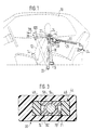
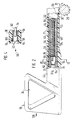
Ein Ausführungsbeispiel der Erfindung ist in der Zeichnung dargestellt und in der nachfolgenden Beschreibung näher erläutert. Es zeigen Figur 1 eine Prinzipdarstellung des Fahrgastraumes eines Kraftfahrzeuges, in welchen die erfindungsgemäße Vorrichtung eingezeichnet ist, Figur 2 ein zu der Vorrichtung gemäß Figur 1 gehörender Zahnstangenabschnitt im Schnitt sowie ein mit diesem verbundenes Haltebauteil für eine Sicherheitsgurt, in vergrößerter Darstellung, Figur 3 einen Querschnitt durch die Zahnstange gemäß Figur 2, entlang der Linie III-III in vergrößerter Darstellung und Figur 4 einen Teilschnitt entlang der Linie IV-IV in Figur 2, vergrößert dargestellt.An embodiment of the invention is shown in the drawing and explained in more detail in the following description. FIG. 1 shows a basic illustration of the passenger compartment of a motor vehicle, in which the device according to the invention is shown, FIG. 2 shows a section of a toothed rack section belonging to the device according to FIG by the rack according to Figure 2, along the line III-III in an enlarged view and Figure 4 shows a partial section along the line IV-IV in Figure 2, enlarged.
In Figur 1 ist mit gestrichelten Linien der Fahrgastzellenbereich 10 eines Kraftfahrzeuges dargestellt. Neben dem einen sichtbaren Fahrgastsitz 12 ist ein zu einem Sicherheitsgurtsystem gehörendes Gurtschloß 14 erkennbar, dem ein Sicherheitsgurt 16 zugeordnet ist. Der Sicherheitsgurt 16 führt von einer karosseriefesten Aufrollvorrichtung 18 über eine Umlenköse 20 zu einem pendelbar am Kraftfahrzeug angeordneten Endbeschlag 22. Diese Umlenköse ist als ringartiges Bauelement ausgebildet und nimmt in seiner Ausnehmung 24 den Sicherheitsgurt 16 lose auf. Die Umlenköse 20 gehört zu einem Sicherheitsgurt-Anbietesystem 26, welches fest mit der Karosserie des Kraftfahrzeuges verbunden ist. Beim Kraftfahrzeug gemäß dem Ausführungsbeispiel nach Figur 1 ist dieses System in der Seitenverkleidung im Bereich der hinteren Sitzbank angeordnet. Bei dem Kraftfahrzeug handelt es sich um ein Coupé, welches nur im Bereich der Vordersitze Türen aufweist, so daß die Karosserie des Fahrzeuges im Bereich der Hintersitze das System aufnehmen kann. Das Sicherheitsgurt-Anbietesystem 26 weist eine elektromotorische Antriebseinheit 28 auf, die als Abriebselement Zahnritzel 29 hat. Das Zahnritzel 29 kämmt mit einer Zahnstange 30, die in einer Führungshülse 32 längsverschiebbar ist. Weiter gehört zu dem Sicherheitsgurt-Anbietesystem 26 noch eine Steuerelektronik 34. Wie aus Figur 1 weiter ersichtlich ist, wird beim Betätigen der Antriebseinheit 23 die Zahnstange 30 zusammen mit der Umlenköse 20 in eine in Figur 1 strichpunktiert dargestellte Anbieteposition 120 überführt. In dieser Anbieteposition befindet sich die Umlenköse 20 vor der auf dem Sitz 12 sitzenden Person, so daß diese den Sicherheitsgurt mit der Einstecklasche 36 ohne Körperverrenkungen greifen und anlegen kann. Während dieser Anbietebewegung, die in Richtung des Pfeiles 38 erfolgt, rollt der Sicherheitsgurt 16 in der Aufrollvorrichtung 18 ab und der Beschlag 22 schwenkt so aus seiner gezeichneten Lage aus, daß eine ordnungsgemäße Gurtführung gewährleistet ist. Nach dem Anlegen des Gurts 16 wird der Umlenkbeschlag 20 wieder in seine in Figur 1 ausgezogen dargestellte Ablegeposition überführt, wobei der Gurtaufroller 18 für eine ordnungsgemäße Anlage des Sicherheitsgurts 16 an der zu sichernden Person sorgt. Die Umlenköse 20 befindet sich wieder neben der Schulter des zu sichernden Fahrgastes. Zu dieser Rückstellbewegung, welche gegen die Richtung des Pfeils 38 erfolgt, wird das Ritzel 29 in einer anderen Drehrichtung (Doppelpfeil 31) angetrieben als dies bei der Anbietebewegung (Pfeil 38) der Fall gewesen ist. Ein zur Antriebseinheit 28 gehörender elektrischer Antriebsmotor ist also drehrichtungsumkehrbar. Weiter ist noch bemerkenswert, daß das Gurt-Anbietesystem 26 so in der Seitenverkleidung des Kraftfahrzeuges untergebracht und angeordnet ist, daß sich die Umlenköse 20 in der Anbieteposition schräg vor der auf dem Sitz 12 sitzenden Person befinden. Die Zahnstange 30 schließt also in ausgefahrenem Zustand mit der Karosserie-Innenwand einen spitzen Winkel ein. An der Innenwand des Kraftfahrzeuges ist ein ganz spezieller Bereich vorbereitet und ausgebildet, an dem die Umlenköse 20 anliegen soll, wenn diese sich in ihrer Ablegeposition befindet, welche in Figur 1 ausgezogen dargestellt ist. Die Beendigung der Rückstellbewegung der Zahnstange 30 bzw. der Umlenköse 20 aus der Anbieteposition 120 entgegen dem Pfeil 38 in die in Figur 1 dargestellte Ablegeposition wird durch einen Schaltnocken bewirkt, der mit einem Endschalter zusammenarbeitet. Dabei ist die Abstimmung dieser beiden Bauteile aufeinander so getroffen, daß alle zulässigen Toleranzen, auch wenn diese auf die selben Seite gelegt werden, nicht die ordnungsgemäße Anlage der Umlenköse 20 an dem definierten Innenbereich 40 des Kraftfahrzeuges beeinträchtigen. Liegen die zulässigen Toleranzen jedoch auf der anderen Seite, wird dies dadurch ausgeglichen, daß die Umlenköse 20 gegenüber der Zahnstange 30 entgegen einer Federkraft in Richtung der Anbietebewegung 38 aus einer Ruhestellung heraus verschiebbar ist. Das Maß der möglichen Verschiebbarkeit ist also größer als das maximale Toleranzmaß, welches sich von dem definierten Innenbereich 40 zur endschalterbedingten Ablegestellung der Zahnstange 30 ergibt. Diese sogenannte Überfederung wird auf folgende Weise erreicht: Die Umlenköse 20 ist ein Bauteil, welches über einen Ansatz 42 mit einem langgestreckten Führungsschlitten 44 verbunden ist. Dieser Führungsschlitten 44 ist in einer Gleitführung 45 der Zahnstange 30 in seiner Längsrichtung verschiebbar geführt. Der Führungsschlitten 44 ist rahmenartig ausgebildet. Er weist somit zwei zueinander im wesentlichen parallele, langgestreckte Rahmenteile 46, 48 auf, die mit Abstand von dem Ansatz 42 über ein Querstück 50 miteinander verbunden sind. Dieses Querstück 50 nimmt ein Zapfenende 52 eines Bolzens 54 auf, der sich innerhalb des Rahmens von dem Querstück 50 zum Ansatz 42 erstreckt. Der Bolzen 54 wird von einer Schrauben-Druckfeder 56 umgeben, die sich mit ihrem einen Ende an der Innenseite des Rahmenteils 50 abstützt. Der Zapfenansatz 52 des Bolzens 54 ist im Durchmesser kleiner als der Durchmesser des Bolzens 54 zwischen den beiden Rahmenteilen 46 und 48, so daß sich der Bolzen 54 mit einem Ringbund an der Innenseite des Rahmenteils 50 abstützt. Der Bolzen 54 ist somit in Längsrichtung des Führungsschlittens festgelegt. Das von dem Zapfenende 52 abgewandte Ende des Führungsbolzens 54 ist in einem Bauelement 58 geführt, welches gegenüber der Zahnstange 30 festgelegt ist. Diese Anordnung ist insbesondere aus den Figuren 2 und 4 ersichtlich. Wie Figur 4 zeigt hat das Bauelement 58 eine Längsbohrung 60, in welcher der Bolzen 54 aufgenommen ist. Das aus einem federelastischen Kunststoff bestehende Bauelement 58 ist mit zwei einander gegenüberliegend angeordneten, über das Ende des Bolzens 54 hinausragenden Federlappen 62 versehen, an deren Außenseite Rastnocken 64 angebracht sind. Zur Montage des Bauteils 58 in der Zahnstange 30 kann das Bauteil 58 in Richtung des Pfeiles 66 in eine die Gleitführung 45 bildende Ausnehmung 69 hineingesteckt werden. Durch die besondere Ausbildung der Federlappen 62 gegenüber dem Bolzen 54 können die Federlappen 62 so weit auslenken, daß die Rastnocken 64 in die Führungsausnehmung 69 der Zahnstange 30 eingeführt werden können. Wenn die Rastnocken 64 in den Bereich von ihnen zugeordneten Rastaufnahmen 69 gelangen, federn diese in die in Figur 4 dargestellte Montageposition, so daß sich eine zahnstangenfeste Anordnung des Bauteils 58 ergibt. Dabei übernimmt die Bohrung 60 Funktion einer Gleitführung für den Bolzen 54. Eine dem Rahmenteil 50 zugewandte Endfläche 70 des Bauteils 58 dient zur Abstützung des anderen Endes der Schrauben-Druckfeder 56, die somit vorgespannt zwischen dem Rahmenteil 50 und dem Bauteil 58 positioniert ist. Die einander zugewandten Innenseiten der Rahmenteile 46 und 48 weisen je zwei miteinander fluchtende Führungsrippen 71, 72 bzw. 74, 76 auf, denen Führungsnuten 78, 80 des Bauteils 58 zugeordnet sind (Figur 3). Zwischen den jeweils miteinander fluchtenden Führungsrippen 70, 72 bzw. 74, 76 ist jeweils ein rippenloser Abstand 82, 84 vorgesehen, der ein problemloses Montieren des Bauteils 58 erlaubt.1 shows the
Wenn nun während des Rücklaufs der Umlenköse 20 in Richtung des Pfeiles 138 - also entgegen der Richtung Pfeil 38 der Anbietebewegung (Figur 1) - die Umlenköse 20 beispielsweise an einem hier mit 84 bezeichneten Bereich an dem definierten Innenbereich 40 des Kraftfahrzeuges zur Anlage kommt, der Endschalter jedoch noch keinen Abschaltimpuls an die Steuerelektronik 34 gibt, erfolgt eine Relativbewegung zwischen der Zahnstange 30 und der Umlenköse 20 mit ihrem Ansatz 42. Die Zahnstange 30 macht dabei eine Bewegung in Richtung des Pfeiles 138 (Figur 2), während die Umlenköse 20 mit ihrem Ansatz 42 am definierten Innenbereich 40 des Kraftfahrzeuges festgehalten wird. Dabei drückt das Bauteil 58, welches mit der Zahnstange 30 fest verbunden ist, die Schrauben-Druckfeder 56 mehr und mehr zusammen, wobei der Führungsschlitten 44 zunehmend aus der Gleitführung 45 herauswandert, bis der Endschalter im Zusammenwirken mit dem Schaltnocken die elektromotorische Antriebseinheit 28 stillsetzt. Zweckmäßigerweise ist noch eine gewisse Ausfederungsreserve mit berücksichtigt, so daß auch Verletzungen von auf den Rücksitzen des Kraftfahrzeugs sitzenden Personen ausgeschlossen werden können, wenn diese beispielsweise an den betreffenden Innenbereich 40 des Kraftfahrzeuges greifen, während die Umlenköse 20 in ihre Ablegeposition läuft. Wenn danach die Umlenköse 20 mit dem Gurt 16 wieder in die Anbietstellung gebracht werden soll, aber die Zahnstange 30 in Richtung des Pfeiles 38 verschoben wird, bleibt die Umlenköse 20 zunächst am Innenbereich 40 angelegt, bis die Druckfeder 56 die der Zahnstange 30 zugewandte Endfläche 88 des Ansatzes 42 an der Zahnstange 30 angelegt hält. Diese in Figur 2 gezeigte Stellung soll als Ruhestellung bezeichnet werden.If, during the return of the deflecting
Es ist klar, daß sich bei dem beschriebenen Ausführungsbeispiel um eine von vielen möglichen Versionen handelt. Beispielsweise ist es denkbar, die Umlenköse 20 direkt an der Zahnstange verschiebbar anzuordnen, ohne daß dabei ein Ansatz 42 vorgesehen sein muß.It is clear that the exemplary embodiment described is one of many possible versions. For example, it is conceivable to arrange the
Claims (5)
- Appliance for the motorized movement of a safety belt (16) in a motor vehicle (10) from a stored position into a proffered position (38), having a longitudinally displaceable rack (30) engaging with a pinion (29) whose drive can be reversed in direction, one end section of which rack (30) is provided with a component (20) loosely holding the safety belt (16), which component (20) runs against a stop configured as the internal region of the motor vehicle (10) during the return motion of the safety belt (16) into the stored position, the component (20) moving out relative to the rack (30) along a guide, characterized in that a frame-type longitudinally extended guide slide (44) is provided for guiding the component (20), which guide slide (44) is in connection with the component (20) and can be displaced against spring force along a sliding guide (45) of the rack (30), a guide pin (54) being arranged and fixed in the longitudinal direction of the guide slide (44) in the region of the latter surrounded by the frame parts (46, 48, 50).
- Appliance according to Claim 1, characterized in that the guide pin (54) is surrounded by a preloaded helical compression spring (56) which is supported at one end on one of the frame parts (50) and is in contact at the other end on a structural element (58) fixed relative to the rack.
- Appliance according to Claim 2, characterized in that the structural element (58) fixed relative to the rack is arranged within the frame parts (46, 48, 50), is connected to the rack (30), is preferably engaged and has a longitudinal hole (60) in which the guide pin (54) is displaceably guided.
- Appliance according to Claim 3, characterized in that the structural element (58) is provided with a guide groove (78, 80) on at least one of its two sides parallel with the axis of the guide pin (54) and in that this guide groove is associated with a guide rib (70, 74) of the guide slide (44).
- Appliance according to one of Claims 1 to 4, characterized in that the structural element (20) has a ring-type configuration and accommodates the safety belt (16) in its opening.
Applications Claiming Priority (5)
| Application Number | Priority Date | Filing Date | Title |
|---|---|---|---|
| DE4025217 | 1990-08-09 | ||
| DE4025217 | 1990-08-09 | ||
| DE4026637A DE4026637A1 (en) | 1990-08-09 | 1990-08-23 | DEVICE FOR MOTORALLY MOVING A BELT IN A MOTOR VEHICLE |
| DE4026637 | 1990-08-23 | ||
| PCT/DE1991/000630 WO1992002388A1 (en) | 1990-08-09 | 1991-08-06 | Device for the motorised movement of a safety belt in a motor vehicle |
Publications (2)
| Publication Number | Publication Date |
|---|---|
| EP0542773A1 EP0542773A1 (en) | 1993-05-26 |
| EP0542773B1 true EP0542773B1 (en) | 1994-11-17 |
Family
ID=25895771
Family Applications (1)
| Application Number | Title | Priority Date | Filing Date |
|---|---|---|---|
| EP91913349A Expired - Lifetime EP0542773B1 (en) | 1990-08-09 | 1991-08-06 | Device for the motorised movement of a safety belt in a motor vehicle |
Country Status (5)
| Country | Link |
|---|---|
| US (1) | US5346256A (en) |
| EP (1) | EP0542773B1 (en) |
| JP (1) | JPH05509271A (en) |
| DE (2) | DE4026637A1 (en) |
| WO (1) | WO1992002388A1 (en) |
Cited By (3)
| Publication number | Priority date | Publication date | Assignee | Title |
|---|---|---|---|---|
| EP1604875A1 (en) * | 2004-06-11 | 2005-12-14 | Robert Bosch Gmbh | Device for the motorized movement of a safety belt in a motor vehicle |
| WO2005120909A1 (en) | 2004-06-11 | 2005-12-22 | Robert Bosch Gmbh | Adjusting device for the motorized movement of a safety belt in a motor vehicle and fixing device and method for fixing the adjusting device |
| WO2006010484A1 (en) * | 2004-07-26 | 2006-02-02 | Autoliv Development Ab | Seat belt extender that extends toward the vehicle occupant |
Families Citing this family (17)
| Publication number | Priority date | Publication date | Assignee | Title |
|---|---|---|---|---|
| DE4223565C1 (en) * | 1992-07-17 | 1993-09-09 | Mercedes-Benz Aktiengesellschaft, 70327 Stuttgart, De | Top car-safety-belt guide-fixing system - has bracket fixed to vertical and horizontal portions of side-panel and protruding upwards alongside window |
| EP0908754A3 (en) | 1994-04-21 | 2000-04-12 | Sega Enterprises, Ltd. | Head mounted display |
| US6274236B1 (en) * | 1995-06-12 | 2001-08-14 | National Label Company | Labels and method of making same |
| DE19901276B4 (en) * | 1999-01-15 | 2007-11-08 | Bayerische Motoren Werke Ag | Bring device for the safety belt in a motor vehicle |
| US6308986B1 (en) * | 1999-04-16 | 2001-10-30 | Joalto Design, Inc. | Restraint belt presenter |
| WO2002009984A1 (en) * | 2000-08-01 | 2002-02-07 | Takata Seat Belts, Inc. | Method of and an apparatus for presenting a seat belt buckle |
| DE10314464B4 (en) * | 2003-03-28 | 2007-05-31 | C. Rob. Hammerstein Gmbh & Co. Kg | Gurtbringer for a safety belt of a motor vehicle |
| DE102004017457B4 (en) * | 2004-04-08 | 2015-01-15 | Trw Automotive Gmbh | Gurtschloßbringer |
| JP2006131090A (en) * | 2004-11-05 | 2006-05-25 | Takata Corp | Tang taking out auxiliary device and seat belt device using the same |
| DE102005029695A1 (en) * | 2005-06-24 | 2006-12-28 | Wilhelm Karmann Gmbh | Device for requesting a safety belt of a vehicle in a convenient position |
| FR2889140B1 (en) * | 2005-07-29 | 2007-10-12 | Daniel Nonat | ASSEMBLY DEVICE FOR ASSEMBLING A SEAT BELT, AND MOTOR VEHICLE EQUIPPED WITH SUCH A DEVICE |
| DE102006056532B4 (en) * | 2006-11-27 | 2014-02-13 | TAKATA Aktiengesellschaft | Vehicle with a belt guide element |
| CN203078469U (en) | 2012-01-20 | 2013-07-24 | 德昌电机(深圳)有限公司 | Safety belt tongue plate actuator |
| DE102012001283B4 (en) * | 2012-01-25 | 2023-08-10 | Zf Automotive Germany Gmbh | Positioning device for a vehicle belt presenter and buckle device |
| DE102014015344B4 (en) * | 2014-10-17 | 2020-01-23 | Trw Automotive Gmbh | Gurtschlossbringer |
| US10196033B2 (en) | 2016-07-18 | 2019-02-05 | Ford Global Technologies, Llc | Seat mounted adjustable seat belt webbing guide |
| DE102019216705B4 (en) * | 2019-10-30 | 2022-02-03 | Autoliv Development Ab | Seat belt presenter and vehicle seat with a seat belt presenter |
Family Cites Families (6)
| Publication number | Priority date | Publication date | Assignee | Title |
|---|---|---|---|---|
| DE2713172C2 (en) * | 1977-03-25 | 1986-08-21 | Daimler-Benz Ag, 7000 Stuttgart | Device for feeding the lock tongue and / or the belt strap of a belt system |
| DE3302163A1 (en) * | 1983-01-22 | 1984-08-02 | Bayerische Motoren Werke AG, 8000 München | DEVICE FOR MOVING A STRAP |
| DE3633902A1 (en) * | 1986-10-04 | 1988-04-07 | Bayerische Motoren Werke Ag | Belt positioning device |
| JPS63270264A (en) * | 1987-04-28 | 1988-11-08 | Mazda Motor Corp | Seat belt for car |
| DE3909360C1 (en) * | 1989-03-22 | 1990-09-20 | Daimler-Benz Aktiengesellschaft, 7000 Stuttgart, De | |
| DE3909361C1 (en) * | 1989-03-22 | 1990-06-28 | Daimler-Benz Aktiengesellschaft, 7000 Stuttgart, De | Device for changing the height of the upper deflection point |
-
1990
- 1990-08-23 DE DE4026637A patent/DE4026637A1/en not_active Withdrawn
-
1991
- 1991-08-06 US US07/977,423 patent/US5346256A/en not_active Expired - Fee Related
- 1991-08-06 WO PCT/DE1991/000630 patent/WO1992002388A1/en active IP Right Grant
- 1991-08-06 DE DE59103549T patent/DE59103549D1/en not_active Expired - Lifetime
- 1991-08-06 EP EP91913349A patent/EP0542773B1/en not_active Expired - Lifetime
- 1991-08-06 JP JP3512505A patent/JPH05509271A/en active Pending
Cited By (3)
| Publication number | Priority date | Publication date | Assignee | Title |
|---|---|---|---|---|
| EP1604875A1 (en) * | 2004-06-11 | 2005-12-14 | Robert Bosch Gmbh | Device for the motorized movement of a safety belt in a motor vehicle |
| WO2005120909A1 (en) | 2004-06-11 | 2005-12-22 | Robert Bosch Gmbh | Adjusting device for the motorized movement of a safety belt in a motor vehicle and fixing device and method for fixing the adjusting device |
| WO2006010484A1 (en) * | 2004-07-26 | 2006-02-02 | Autoliv Development Ab | Seat belt extender that extends toward the vehicle occupant |
Also Published As
| Publication number | Publication date |
|---|---|
| EP0542773A1 (en) | 1993-05-26 |
| WO1992002388A1 (en) | 1992-02-20 |
| JPH05509271A (en) | 1993-12-22 |
| DE4026637A1 (en) | 1992-02-13 |
| DE59103549D1 (en) | 1994-12-22 |
| US5346256A (en) | 1994-09-13 |
Similar Documents
| Publication | Publication Date | Title |
|---|---|---|
| EP0542773B1 (en) | Device for the motorised movement of a safety belt in a motor vehicle | |
| DE19632560C2 (en) | Headrest locking device | |
| DE19717666B4 (en) | Gurtintegralsitz a motor vehicle with a backrest, a headrest and a Gurtführungseinrichtung | |
| DE102009024292B4 (en) | Belt retractor for a safety belt of a motor vehicle | |
| DE102006001143B3 (en) | Headrest for vehicle, comprises manually operated mechanism for returning unit to prior position after crash | |
| EP1838561B1 (en) | Height-adjustable deflection device for a three-point seat-belt, vehicle seat comprising a three-point seat-belt and method for adjusting the height of the upper retaining point of a three-point seat-belt | |
| DE102009001308B4 (en) | Electrically height-adjustable headrest device for a motor vehicle seat | |
| EP3478533A1 (en) | Longitudinal adjuster and vehicle seat | |
| DE3415930A1 (en) | Roller blind for a motor vehicle window | |
| EP1871647B1 (en) | Seat-belt presenter for a motor vehicle | |
| EP1500564A1 (en) | Vehicle occupant restraint system | |
| EP0232483B1 (en) | Device for the incremental adjustment of the height of an anchorage or guide pulley for a seat belt or the like | |
| DE102018108829A1 (en) | retaining element | |
| EP3144177B1 (en) | Locking system for a seat assembly of a motor vehicle | |
| DE3002500A1 (en) | DEVICE FOR ADJUSTING THE POSITION OF A REPLACABLE ELEMENT IN A VEHICLE, EXAMPLE OF THE VEHICLE SEAT | |
| DE3541179C2 (en) | Device for the continuous adjustment of a seat belt anchor point | |
| EP1989083B1 (en) | Method for controlling a belt hand-over device and belt hand-over device for a motor vehicle | |
| EP1738942B1 (en) | Motor vehicle window blind with a stop rigidly fixed to the drive linkage | |
| EP1057696B1 (en) | Roll-over protection device for motor vehicles | |
| EP0802095B1 (en) | Safety belt system | |
| DE2023957C3 (en) | Anchoring fitting for seat belts | |
| DE102006041261A1 (en) | Rollover protection system for cabriolet vehicle, has tooth profile, which is formed as separate tooth sensing element, and is guided in channel that opens to tooth meshing side at rollover element | |
| EP1361325B1 (en) | Actuator for closures of vehicles | |
| DE102004057106B4 (en) | Predisplaceable motor vehicle seat | |
| DE19901276B4 (en) | Bring device for the safety belt in a motor vehicle |
Legal Events
| Date | Code | Title | Description |
|---|---|---|---|
| PUAI | Public reference made under article 153(3) epc to a published international application that has entered the european phase |
Free format text: ORIGINAL CODE: 0009012 |
|
| 17P | Request for examination filed |
Effective date: 19930203 |
|
| AK | Designated contracting states |
Kind code of ref document: A1 Designated state(s): DE FR IT |
|
| RAP1 | Party data changed (applicant data changed or rights of an application transferred) |
Owner name: MERCEDES-BENZ AG Owner name: ROBERT BOSCH GMBH |
|
| 17Q | First examination report despatched |
Effective date: 19931202 |
|
| GRAA | (expected) grant |
Free format text: ORIGINAL CODE: 0009210 |
|
| AK | Designated contracting states |
Kind code of ref document: B1 Designated state(s): DE FR IT |
|
| REF | Corresponds to: |
Ref document number: 59103549 Country of ref document: DE Date of ref document: 19941222 |
|
| ET | Fr: translation filed | ||
| ITF | It: translation for a ep patent filed |
Owner name: STUDIO JAUMANN |
|
| PGFP | Annual fee paid to national office [announced via postgrant information from national office to epo] |
Ref country code: FR Payment date: 19950816 Year of fee payment: 5 |
|
| PLBE | No opposition filed within time limit |
Free format text: ORIGINAL CODE: 0009261 |
|
| STAA | Information on the status of an ep patent application or granted ep patent |
Free format text: STATUS: NO OPPOSITION FILED WITHIN TIME LIMIT |
|
| 26N | No opposition filed | ||
| PG25 | Lapsed in a contracting state [announced via postgrant information from national office to epo] |
Ref country code: FR Effective date: 19970430 |
|
| PG25 | Lapsed in a contracting state [announced via postgrant information from national office to epo] |
Ref country code: IT Free format text: LAPSE BECAUSE OF NON-PAYMENT OF DUE FEES;WARNING: LAPSES OF ITALIAN PATENTS WITH EFFECTIVE DATE BEFORE 2007 MAY HAVE OCCURRED AT ANY TIME BEFORE 2007. THE CORRECT EFFECTIVE DATE MAY BE DIFFERENT FROM THE ONE RECORDED. Effective date: 20050806 |
|
| PGFP | Annual fee paid to national office [announced via postgrant information from national office to epo] |
Ref country code: DE Payment date: 20101025 Year of fee payment: 20 |
|
| REG | Reference to a national code |
Ref country code: DE Ref legal event code: R071 Ref document number: 59103549 Country of ref document: DE |
|
| REG | Reference to a national code |
Ref country code: DE Ref legal event code: R071 Ref document number: 59103549 Country of ref document: DE |
|
| PG25 | Lapsed in a contracting state [announced via postgrant information from national office to epo] |
Ref country code: DE Free format text: LAPSE BECAUSE OF EXPIRATION OF PROTECTION Effective date: 20110807 |