EP0542601B1 - Hooking system for handling-device for trapezoidal containers - Google Patents
Hooking system for handling-device for trapezoidal containers Download PDFInfo
- Publication number
- EP0542601B1 EP0542601B1 EP92402973A EP92402973A EP0542601B1 EP 0542601 B1 EP0542601 B1 EP 0542601B1 EP 92402973 A EP92402973 A EP 92402973A EP 92402973 A EP92402973 A EP 92402973A EP 0542601 B1 EP0542601 B1 EP 0542601B1
- Authority
- EP
- European Patent Office
- Prior art keywords
- hook
- spindle
- shaft
- pin
- central
- Prior art date
- Legal status (The legal status is an assumption and is not a legal conclusion. Google has not performed a legal analysis and makes no representation as to the accuracy of the status listed.)
- Expired - Lifetime
Links
Images


Classifications
-
- B—PERFORMING OPERATIONS; TRANSPORTING
- B60—VEHICLES IN GENERAL
- B60P—VEHICLES ADAPTED FOR LOAD TRANSPORTATION OR TO TRANSPORT, TO CARRY, OR TO COMPRISE SPECIAL LOADS OR OBJECTS
- B60P1/00—Vehicles predominantly for transporting loads and modified to facilitate loading, consolidating the load, or unloading
- B60P1/48—Vehicles predominantly for transporting loads and modified to facilitate loading, consolidating the load, or unloading using pivoted arms raisable above load-transporting element
Definitions
- the invention relates to the handling of trapezoidal skips which are provided in the upper part, on each lateral face, with two projecting lugs for hanging the end of a chain, and in the lower part on each transverse face, with a or two tilting axis (s) oriented horizontally and parallel to the transverse face.
- the handling device furthermore comprises a hooking system with one or two hook (s) disposed rearward and approximately at the level where the bucket rests when 'it is loaded on the vehicle. In the position cleared, each hook is lowered so that it is outside the path of the bucket when it is loaded or unloaded, while in the hooking position each hook is raised and arranged in the path of the axis corresponding to it.
- a hooking system with one or two hook (s) disposed rearward and approximately at the level where the bucket rests when 'it is loaded on the vehicle. In the position cleared, each hook is lowered so that it is outside the path of the bucket when it is loaded or unloaded, while in the hooking position each hook is raised and arranged in the path of the axis corresponding to it.
- the bucket If the arms, hooked by the chains to a bucket loaded on the vehicle, are then tilted back, the bucket describes the same movement as before until the tilt axis (s) located on the lower part of the rear transverse face of the bucket engages in the hook (s), the bucket then no longer remaining horizontal but tilting around the axis (s) so that it empties behind the vehicle.
- the movement On the return, when the arms are tilted forward, the movement is similar, that is to say that the bucket pivots around the axis (s) of grip until it (these) disengage (s) from the hook (s), the end of the movement being similar to loading.
- the invention relates to a fastening system which can be used both for tipping bodies with a centrally arranged tilting axis (German standard DIN 30720) and for tipping bodies with two tilting axes arranged laterally (French standard NF R 17-106 ).
- a fastening system for a trapezoidal skip handling device comprising at least one hook adapted to cooperate with a tilting axis of a said skip and hook mounting means comprising a shaft pivotally mounted on the handling device; characterized in that said shaft is suitable for mounting three hooks: a central hook adapted to cooperate with buckets of the type comprising a central tilting axis, and two lateral hooks adapted to cooperate with buckets of the type comprising two lateral tilting axes , each hook being able to be released in rotation with respect to the shaft.
- the system according to the invention offers the advantage of being particularly simple with respect to previous systems which included two concentric shafts controlled independently by two different jacks, one of these shafts carrying the two lateral hooks and the other shaft the central hook.
- each hook is blocked with respect to the shaft by means of a removable pin.
- the pin is indeed a particularly simple, convenient and economical means for coupling or releasing in rotation the hook opposite the shaft.
- said shaft is pivotally mounted by means of at least two vertical supports forming a bearing, it is axially blocked by means of a removable means cooperating with at least one said support, and it comprises a lever for control blocked with respect to the shaft by a removable means.
- the invention is particularly advantageous compared to previous systems where the hook (s) was (were) always welded (s) on the shaft, and where therefore it was necessary to largely rebuild the system d 'hooking when you wanted to go from a one hook system to a two hook system or vice versa.
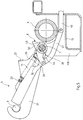
- the attachment system illustrated in Figures 1 to 8 is intended to cooperate as indicated above with trapezoidal buckets 1, the lower part of the transverse inclined pan 2 has a central tilting axis 3 disposed horizontally and parallel to the inclined pan 6).
- This system comprises a central hook 4 adapted to cooperate with the axis 3; hook mounting means 4 allowing it to pass from a hooking position where it is raised (see Figures 1 to 3) to a cleared position where it is lowered (see Figure 7) by turning in a lowering direction illustrated by arrow 5, and from the cleared position to the latching position by turning in the lifting direction illustrated by arrow 6; as well as means for opposing the lowering of the hook 4 when it is in the hooking position.
- the hook mounting means 4 comprise a shaft 7 pivotally mounted on the device handling, the hook itself being pivotally mounted on the shaft 7; a lifting stop 8 secured to the shaft 7 to stop lifting the hook when it has reached the hooking position, the stop 8 then being supported on the round transverse rear beam 9 of the handling device (see FIGS.
- a second stop 10 integral with the stop 8 (and therefore of the shaft 7) and arranged so that the hook is in the hooking position when it is in abutment on the abutment 10 while the abutment 8 is in abutment on the beam 9; and a tension spring 11 connected to the shaft 7 at a first end and to the hook 4 at a second end, which biases the hook 4 towards the stop 10 in the lowering direction 5 when the hook is in the position hanging (see figures 2 and 3).
- the shaft 7 is pivotally mounted on the handling device by means of three vertical supports 12A, 12B and 12C welded to the low rear beam 13 with an L-shaped section of the handling device, these supports forming a bearing for the shaft 7, that -this being axially blocked by a washer 14 disposed outside each external support 12A and 12C, and by a pin 15 fixed transversely in the shaft 7 and bearing on the external side of the washer 14.
- the hook 4 comprises a flange 20 pivotally mounted on the shaft 7 and a tab 21 with a curved end pivotally mounted on the flange 20, abutment means being provided so that the tab 21 is movable relative to the flange 20 between a first extreme position where the spout 22 formed by the curved end of the tab 21 is released from the flange 20 (see Figures 1 to 3) and a second extreme position where the flange 20 closes the spout 22 (see Figure 4).
- the spring 11 is fixed to the hook 4 by the tab 21, by virtue of a projecting rod 23 welded transversely to the tab 21.
- the different elements including the tree 7, the stop 10, the flange 20, the lug 21 and the spring 11 are adapted to cooperate, when the stop 8 is in abutment on the beam 9, so that the hook spontaneously adopts the attachment configuration illustrated in FIGS. 1 at 3, where the hook is in the first extreme position with the flange bearing on the stop 10; so that if the hook is biased in the lifting direction 6, then the flange 20 and the lug 21 rock against the spring 11 in the direction 6 (see FIG.
- the flange 20 is double and has a cheek 24 on each side of the lug 21, each cheek connecting to a ring 25 surrounding the shaft 7, the lug 21 being articulated on a pin 26 fixed on the cheeks 24.
- a trigger guard 27 connects the cheeks 24 and forms part of the own stop means for the hook, the latter being in the first extreme position when the tab 21 is in abutment on the trigger guard 27.
- the rod 23 also forms part of the stop means specific to the hook 4 , the latter being in the second extreme position when the rod 23 is in abutment on a cheek 24 (see FIGS. 4 and 5).
- the axis 28 of the shaft 7, which is also the pivot axis of the flange on the shaft 7, that the axis 29 of the pin 26, which is the pivot axis of the lug 21 on the flange 20, and that the geometric axis of the tilt axis 3 are substantially coplanar in the second extreme position (see Figures 4 and 5).
- the lifting stop 8 and the second stop 10 are joined on a common element 30 which comprises a ring 31 surrounding the shaft 7 and a member 32 in the shape of a T whose base corresponds to the stop 8 and the bottom of one of the sides of the horizontal branch at the second stop 10.
- the common element 30 is secured to the shaft 7 by means of a transverse pin 33 (see FIG. 8) which passes through a suitable hole 33 'in the shaft 7 (see figure 9).
- the hook 4 is blocked in translation on one side by the support 12B and on the other side by the common element 30, and it is by a small arch 34 fixed on the element 30 that the spring 11 is connected to tree 7.
- the means for opposing the lowering of the hook when it is in the hooking position comprise a control jack whose rod 40 is connected to the shaft 7 by means of a link 41 articulated on the rod 40 and on a lever 42 secured to the shaft, which comprises a ring 43 surrounding the shaft 7 and two cheeks 44 between which the link 41 is articulated.
- the lever 42 is secured to the shaft 7 by means of a pin 45 which passes through a appropriate shaft hole 7 (see figure 8).
- control jack When the control jack takes out its rod 40, then it rotates the shaft 7 and the hook 4 in the direction 6, the lifting stops when the stop 8 comes to bear on the beam 9. The jack then tends to keep its rod out position, that is to say that it opposes the lowering of the hook.
- FIGS. 1 to 8 To use the attachment system illustrated in FIGS. 1 to 8, one generally starts from the erased position shown in FIG. 7, where the hook is lowered.
- Figure 6 shows a case where the axis 3 has not cleared, so that the bucket pulled forward on the hook 4, and tilted it in the direction of lifting 6 to the against the spring 11. It will be noted that the hook has been able to tilt until the bucket rests on a loading support 51 of the handling device.
- the attachment system 60 is provided to cooperate with skips which have two lateral tilt axes rather than a central axis.
- the system 60 is similar to the system illustrated in FIGS. 1 to 8, but with two lateral hooks instead of a central hook.
- the elements used being identical: the hook 4 on the left is axially locked between the support 12A and the common element 30 pinned in the hole 61 (see FIG. 8), and the hook 4 on the right is axially blocked between the support 12C and the common element 30 pinned in the hole 62.
- the attachment system 70 is designed to cooperate either with skips which have a central tilting axis, or with skips which have two lateral tilting axes
- the system 70 is similar to the system illustrated in FIGS. 1 to 8, or in FIG. 9, but with a central hook mounted as in FIGS. 1 to 8 and two lateral hooks mounted as in FIG. 9.
- the hook 4 is replaced by a tab with a curved end articulated directly on the shaft 7 and returning directly in contact with the stop 10.
- each hook can be completely immobilized with a pin opposite the shaft 7, with a lifting stop secured to the hook.
- the lifting stop is not directly part of the hook, but is pinned on the axis independently of the hook: in the event of blocking, it can be provided that it is one of the pins of a hook or of the stop of lifting which breaks, using pins adapted to break under a predetermined torque.
Abstract
Description
L'invention a trait à la manutention des bennes de forme trapézoïdale qui sont munies en partie haute, sur chaque face latérale, de deux pattes en saillie pour accrocher le bout d'une chaîne, et en partie basse sur chaque face transversale, de un ou deux axe(s) de basculement orienté(s) horizontalement et parallèlement à la face transversale.The invention relates to the handling of trapezoidal skips which are provided in the upper part, on each lateral face, with two projecting lugs for hanging the end of a chain, and in the lower part on each transverse face, with a or two tilting axis (s) oriented horizontally and parallel to the transverse face.
On sait que ces bennes sont destinées à être manipulées par un dispositif, généralement monté sur un véhicule, qui comporte de chaque côté un bras articulé à sa base autour d'un axe horizontal tandis qu'à son sommet sont fixées à un point commun deux chaînes de même longueur dont l'extrémité libre de chacune est destinée à être accrochée sur l'une des pattes en saillie sur la partie haute de la face latérale correspondante de la benne. Pour charger ou décharger la benne, on fait pivoter simultanément les deux bras, les chaînes se tendent, la benne est soulevée et décrit un arc de cercle - centré sur l'axe commun de pivotement des bras - en restant horizontale, l'ensemble benne-chaînes pivotant sous l'effet de la gravité autour de l'axe passant par les deux points communs d'accrochage des chaînes. Pour permettre de vider le contenu de la benne derrière le véhicule, le dispositif de manutention comporte en outre un système d'accrochage avec un ou deux crochet(s) disposé(s) en arrière et à peu près au niveau où repose la benne lorsqu'elle est chargée sur le véhicule. Dans la position effacée, chaque crochet est abaissé de sorte qu'il est en dehors du trajet de la benne lorsque celle-ci est chargée ou déchargée, tandis qu'en position d'accrochage chaque crochet est relevé et disposé dans le trajet de l'axe de basculement qui lui correspond. Si les bras, accrochés par les chaînes à une benne chargée sur le véhicule, sont alors basculés en arrière, la benne décrit le même mouvement que précédemment jusqu'à ce que le ou les axe(s) de basculement situé(s) sur la partie basse de la face transversale arrière de la benne s'engage(nt) dans le(s) crochet(s), la benne ne restant alors plus horizontale mais basculant autour du ou des axe(s) de sorte qu'elle se vide derrière le véhicule. Au retour, lorsqu'on fait basculer les bras en avant, le mouvement est similaire, c'est-à-dire que la benne pivote autour de l'(des) axe(s) de préhension jusqu'à ce que celui-ci (ceux-ci) se dégage(nt) du (des) crochet(s), la fin du mouvement étant similaire au chargement.We know that these skips are intended to be handled by a device, generally mounted on a vehicle, which comprises on each side an arm articulated at its base around a horizontal axis while at its top are fixed at a common point two chains of the same length, the free end of each of which is intended to be hung on one of the projecting lugs on the upper part of the corresponding side face of the bucket. To load or unload the bucket, the two arms are pivoted simultaneously, the chains are tightened, the bucket is raised and describes an arc of a circle - centered on the common pivot axis of the arms - remaining horizontal, the bucket assembly -chains pivoting under the effect of gravity around the axis passing through the two common points of attachment of the chains. To allow the contents of the bucket to be emptied behind the vehicle, the handling device furthermore comprises a hooking system with one or two hook (s) disposed rearward and approximately at the level where the bucket rests when 'it is loaded on the vehicle. In the position cleared, each hook is lowered so that it is outside the path of the bucket when it is loaded or unloaded, while in the hooking position each hook is raised and arranged in the path of the axis corresponding to it. If the arms, hooked by the chains to a bucket loaded on the vehicle, are then tilted back, the bucket describes the same movement as before until the tilt axis (s) located on the lower part of the rear transverse face of the bucket engages in the hook (s), the bucket then no longer remaining horizontal but tilting around the axis (s) so that it empties behind the vehicle. On the return, when the arms are tilted forward, the movement is similar, that is to say that the bucket pivots around the axis (s) of grip until it (these) disengage (s) from the hook (s), the end of the movement being similar to loading.
L'invention vise un système d'accrochage qui puisse convenir aussi bien aux bennes à un axe de basculement disposé de façon centrale (norme allemande DIN 30720) qu'aux bennes à deux axes de basculement disposés latéralement (norme française NF R 17-106).The invention relates to a fastening system which can be used both for tipping bodies with a centrally arranged tilting axis (German standard DIN 30720) and for tipping bodies with two tilting axes arranged laterally (French standard NF R 17-106 ).
Elle propose à cet effet un système d'accrochage pour dispositif de manutention de bennes trapézoïdales, comportant au moins un crochet adapté à coopérer avec un axe de basculement d'une dite benne et des moyens de montage du crochet comportant un arbre monté à pivotement sur le dispositif de manutention ; caractérisé en ce que ledit arbre est adapté au montage de trois crochets : un crochet central adapté à coopérer avec des bennes du type comportant un axe de basculement central, et deux crochets latéraux adaptés à coopérer avec des bennes du type comportant deux axes de basculement latéraux, chaque crochet pouvant être libéré en rotation vis à vis de l'arbre.To this end, it offers a fastening system for a trapezoidal skip handling device, comprising at least one hook adapted to cooperate with a tilting axis of a said skip and hook mounting means comprising a shaft pivotally mounted on the handling device; characterized in that said shaft is suitable for mounting three hooks: a central hook adapted to cooperate with buckets of the type comprising a central tilting axis, and two lateral hooks adapted to cooperate with buckets of the type comprising two lateral tilting axes , each hook being able to be released in rotation with respect to the shaft.
Ainsi, en supposant que l'on ait monté les trois crochets sur l'arbre, il suffit de libérer le crochet central tout en laissant les crochets latéraux attelés en rotation, pour pouvoir utiliser le système avec une benne à deux axes de basculement, ou alors de libérer les deux crochets latéraux tout en gardant l'attelage du crochet central pour l'utilisation avec une benne à un axe de basculement : seul le ou les crochet(s) qui continue(nt) à être attelé(s) est (sont) opérationnel(s), on évite la configuration interdite où les trois crochets seraient opérationnels en même temps.Thus, assuming that the three hooks have been mounted on the shaft, it suffices to release the central hook while leaving the lateral hooks coupled in rotation, in order to be able to use the system with a bucket with two tilting axes, or then release the two lateral hooks while keeping the central hook coupling for use with a bucket with a tilting axis: only the hook (s) which continue to be coupled is ( are) operational, avoid the prohibited configuration where the three hooks would be operational at the same time.
Le système selon l'invention offre l'avantage d'être particulièrement simple vis à vis des systèmes antérieurs qui comportaient deux arbres concentriques commandés indépendamment par deux vérins différents, l'un de ces arbres portant les deux crochets latéraux et l'autre arbre le crochet central.The system according to the invention offers the advantage of being particularly simple with respect to previous systems which included two concentric shafts controlled independently by two different jacks, one of these shafts carrying the two lateral hooks and the other shaft the central hook.
Selon des caractéristiques préférées de l'invention, chaque crochet est bloqué vis à vis de l'arbre grâce à une goupille démontable.According to preferred features of the invention, each hook is blocked with respect to the shaft by means of a removable pin.
La goupille est en effet un moyen particulièrement simple, commode et économique pour atteler ou libérer en rotation le crochet vis à vis de l'arbre.The pin is indeed a particularly simple, convenient and economical means for coupling or releasing in rotation the hook opposite the shaft.
Selon d'autres caractéristiques préférées de l'invention, ledit arbre est monté à pivotement grâce à au moins deux supports verticaux formant palier, il est bloqué axialement grâce à un moyen démontable coopérant avec au moins un dit support, et il comporte un levier de commande bloqué vis à vis de l'arbre grâce à un moyen démontable.According to other preferred characteristics of the invention, said shaft is pivotally mounted by means of at least two vertical supports forming a bearing, it is axially blocked by means of a removable means cooperating with at least one said support, and it comprises a lever for control blocked with respect to the shaft by a removable means.
Avec ces caractéristiques, lorsqu'on libère tous les blocages, il est possible de démonter l'arbre en le faisant coulisser axialement. Par conséquent, si le véhicule est initialement prévu pour être utilisé avec des bennes à un axe de basculement central, on peut très bien monter uniquement le crochet central, et si par la suite le véhicule doit pouvoir travailler également avec des bennes à deux axes de basculement ou uniquement avec des bennes à deux axes de basculement, il est particulièrement aisé de rajouter les deux crochets latéraux, en gardant ou non le crochet central.With these characteristics, when all blockages are released, it is possible to disassemble the shaft by sliding it axially. Consequently, if the vehicle is initially intended to be used with skips with a central tilting axis, it is very possible to mount only the central hook, and if the vehicle must subsequently be able to work also with skips with two tilting axes or only with skips with two tilting axes, it is particularly easy to add the two lateral hooks, keeping or not the central hook.
On voit que l'invention est particulièrement avantageuse par rapport aux systèmes antérieurs où le ou les crochet(s) étai(en)t toujours soudé(s) sur l'arbre, et où par conséquent il fallait reconstruire en grande partie le système d'accrochage quand on voulait passer d'un système à un crochet à un système à deux crochets ou inversement.We see that the invention is particularly advantageous compared to previous systems where the hook (s) was (were) always welded (s) on the shaft, and where therefore it was necessary to largely rebuild the system d 'hooking when you wanted to go from a one hook system to a two hook system or vice versa.
L'exposé de l'invention sera maintenant poursuivi par la description d'exemples de réalisation, donnée ci-après à titre illustratif et non limitatif, en référence aux dessins annexés. Sur ceux-ci :
- la figure 1 est une perspective partielle simplifiée d'un système conforme à l'invention, prise depuis l'arrière et la gauche d'un véhicule équipé d'un dispositif de manutention de bennes trapézoïdales, le système d'accrochage illustré comportant un crochet central et étant montré en position d'accrochage ;
- la figure 2 est une perspective partielle schématique de ce système dans la même position, prise depuis le côté droit du véhicule et en avant de la partie du système représenté ;
- la figure 3 est une vue de droite en coupe, correspondant à la figure 2 ;
- la figure 4 est une perspective similaire à la figure 2 mais montrant le crochet dans la position de verrouillage d'un axe de basculement de benne qu'il adopte après que la patte à bout recourbé ait été entraînée vers l'arrière par cet axe de basculement ;
- la figure 5 est une vue similaire à la figure 3, mais montrant le système en cours de basculement de la benne ;
- la figure 6 est une vue similaire à la figure 3, mais montrant le crochet dans une position basculée sur l'avant qu'il a adoptée après avoir été entraîné lors du retour de basculement au delà de la position d'accrochage par la benne qui ne s'est pas décrochée ;
- la figure 7 est une vue similaire à la figure 3, mais montrant le système avec le crochet en position effacée ;
- la figure 8 est une vue de derrière partielle du système, correspondant aux figures 2, 3 ou 4, la patte à bout recourbé du crochet et le ressort n'étant pas représentés ;
- la figure 9 est une vue similaire à la figure 8, dans une variante à deux crochets latéraux plutôt qu'un crochet central ; et
- la figure 10 est une vue similaire à la figure 9, dans une variante à trois crochets avec les deux crochets latéraux goupillés et le crochet central dégoupillé.
- Figure 1 is a simplified partial perspective of a system according to the invention, taken from the rear and the left of a vehicle equipped with a device for handling trapezoidal bins, the attachment system illustrated comprising a hook central and being shown in the hanging position;
- Figure 2 is a partial schematic perspective of this system in the same position, taken from the right side of the vehicle and in front of the part of the system shown;
- Figure 3 is a sectional right view, corresponding to Figure 2;
- Figure 4 is a perspective similar to Figure 2 but showing the hook in the locking position of a skip tilting axis that it adopts after the tab with curved end has been driven rearward by this axis of tilting;
- Figure 5 is a view similar to Figure 3, but showing the system during tipping of the bucket;
- Figure 6 is a view similar to Figure 3, but showing the hook in a tilted position on the front which it adopted after having been driven during the tilting return beyond the position for hooking by the bucket which has not come off;
- Figure 7 is a view similar to Figure 3, but showing the system with the hook in the erased position;
- Figure 8 is a partial rear view of the system, corresponding to Figures 2, 3 or 4, the tab with curved end of the hook and the spring not being shown;
- Figure 9 is a view similar to Figure 8, in a variant with two side hooks rather than a central hook; and
- Figure 10 is a view similar to Figure 9, in a variant with three hooks with the two side hooks pinned and the central hook unlocked.
Le système d'accrochage illustré sur les figures 1 à 8 est prévu pour coopérer comme indiqué précédemment avec des bennes trapézoïdales 1 dont la partie basse du pan incliné transversal 2 comporte un axe central de basculement 3 disposé horizontalement et parallèlement au pan incliné (voir figure 6).The attachment system illustrated in Figures 1 to 8 is intended to cooperate as indicated above with trapezoidal buckets 1, the lower part of the transverse
Ce système comporte un crochet central 4 adapté à coopérer avec l'axe 3 ; des moyens de montage du crochet 4 lui permettant de passer d'une position d'accrochage où il est relevé (voir figures 1 à 3) à une position effacée où il est abaissé (voir figure 7) en tournant dans un sens d'abaissement illustré par la flèche 5, et de la position effacée à la position d'accrochage en tournant dans le sens de relevage illustré par la flèche 6 ; ainsi que des moyens pour s'opposer à l'abaissement du crochet 4 quand il est en position d'accrochage.This system comprises a
Les moyens de montage du crochet 4 comportent un arbre 7 monté à pivotement sur le dispositif de manutention, le crochet étant lui-même monté à pivotement sur l'abre 7 ; une butée de relevage 8 solidarisée à l'arbre 7 pour arrêter le relevage du crochet quand il est parvenu en position d'accrochage, la butée 8 étant alors en appui sur la poutre arrière transversale ronde 9 du dispositif de manutention (voir figures 2 et 3) ; une deuxième butée 10 solidaire de la butée 8 (et donc de l'arbre 7) et disposée de sorte que le crochet est en position d'accrochage quand il est en appui sur la butée 10 alors que la butée 8 est en appui sur la poutre 9 ; et un ressort de traction 11 connecté à l'arbre 7 à une première extrémité et au crochet 4 à une deuxième extrémité, qui sollicite le crochet 4 vers la butée 10 dans le sens d'abaissement 5 quand le crochet est dans la position d'accrochage (voir figures 2 et 3).The hook mounting means 4 comprise a
L'arbre 7 est monté à pivotement sur le dispositif de manutention grâce à trois supports verticaux 12A, 12B et 12C soudés sur la poutre arrière basse 13 à section en L du dispositif de manutention, ces supports formant palier pour l'arbre 7, celui-ci étant bloqué axialement grâce à une rondelle 14 disposée à l'extérieur de chaque support externe 12A et 12C, et à une goupille 15 fixée transversalement dans l'arbre 7 et portant sur le coté externe de la rondelle 14.The
Le crochet 4 comporte un flasque 20 monté à pivotement sur l'abre 7 et une patte 21 à bout recourbé montée à pivotement sur le flasque 20, des moyens de butée étant prévus pour que la patte 21 soit mobile par rapport au flasque 20 entre une première position extrême où le bec 22 formé par le bout recourbé de la patte 21 est dégagé du flasque 20 (voir figures 1 à 3) et une deuxième position extrême où le flasque 20 ferme le bec 22 (voir figure 4).The
Le ressort 11 est fixé au crochet 4 par la patte 21, grâce à une tige en saillie 23 soudée transversalement sur la patte 21.The
Les différents éléments, et notamment l'arbre 7, la butée 10, le flasque 20, la patte 21 et le ressort 11 sont adaptés à coopérer, lorsque la butée 8 est en appui sur la poutre 9, pour que le crochet adopte spontanément la configuration d'accrochage illustrée sur les figures 1 à 3, où le crochet est dans la première position extrême avec le flasque en appui sur la butée 10 ; pour que si le crochet est sollicité dans le sens de relevage 6, alors le flasque 20 et la patte 21 basculent à l'encontre du ressort 11 dans le sens 6 (voir figure 6) ; et pour que si la patte 21 est sollicitée à partir de la configuration d'accrochage dans le sens d'abaissement 5, alors la patte 21 pivote par rapport au flasque 20 dans le sens 5, jusqu'à la deuxième position extrême (voir figure 4), de sorte que quand le crochet 4 retient une benne en cours de basculement, son bec est fermé par le flasque 20 (voir figure 5).The different elements, including the
Le flasque 20 est double et comporte une joue 24 de chaque côté de la patte 21, chaque joue se raccordant à une bague 25 entourant l'arbre 7, la patte 21 étant articulée sur un tourillon 26 fixé sur les joues 24. Un pontet 27 relie les joues 24 et fait partie des moyens de butée propres au crochet, celui-ci étant dans la première position extrême quand la patte 21 est en appui sur le pontet 27. La tige 23 fait également partie des moyens de butée propres au crochet 4, celui-ci étant dans la deuxième position extrême quand la tige 23 est en appui sur une joue 24 (voir figures 4 et 5).The
On notera que l'axe 28 de l'arbre 7, qui est également l'axe de pivotement du flasque sur l'arbre 7, que l'axe 29 du tourillon 26, qui est l'axe de pivotement de la patte 21 sur le flasque 20, et que l'axe géométrique de l'axe de basculement 3 sont sensiblement coplanaires dans la deuxième position extrême (voir figures 4 et 5).Note that the
La butée de relevage 8 et la deuxième butée 10 sont réunies sur un élément commun 30 qui comporte une bague 31 entourant l'arbre 7 et un membre 32 en forme de T dont la base correspond à la butée 8 et le dessous d'un des côtés de la branche horizontale à la deuxième butée 10. La solidarisation de l'élément commun 30 à l'arbre 7 est obtenue grâce à une goupille transversale 33 (voir figure 8) qui passe dans un trou approprié 33' de l'arbre 7 (voir figure 9).The
Le crochet 4 est bloqué en translation d'un côté par le support 12B et de l'autre côté par l'élément commun 30, et c'est par un petit arceau 34 fixé sur l'élément 30 que le ressort 11 est connecté à l'arbre 7.The
Les moyens pour s'opposer à l'abaissement du crochet quand il est en position d'accrochage, comportent un vérin de commande dont la tige 40 est reliée à l'arbre 7 grâce à une biellette 41 articulée sur la tige 40 et sur un levier 42 solidarisé à l'arbre, qui comporte une bague 43 entourant l'arbre 7 et deux joues 44 entre lesquelles s'articule la biellette 41. Le levier 42 est solidarisé à l'arbre 7 grâce à une goupille 45 qui passe dans un trou approprié de l'arbre 7 (voir figure 8).The means for opposing the lowering of the hook when it is in the hooking position, comprise a control jack whose
Lorsque le vérin de commande sort sa tige 40, alors il fait pivoter l'arbre 7 et le crochet 4 dans le sens 6, le relevage s'arrêtant quand la butée 8 vient en appui sur la poutre 9. Le vérin tend alors à garder sa position tige sortie, c'est-à-dire qu'il s'oppose à l'abaissement du crochet.When the control jack takes out its
Pour utiliser le système d'accrochage illustré sur les figures 1 à 8, on part généralement de la position effacée montrée sur la figure 7, où le crochet est abaissé.To use the attachment system illustrated in FIGS. 1 to 8, one generally starts from the erased position shown in FIG. 7, where the hook is lowered.
On fait alors sortir la tige du vérin de commande, ce qui amène le système à la position d'accrochage montrée sur les figures 1 à 3. Le système est ainsi prêt à intercepter, par le crochet 4, l'axe de basculement 3 de la benne 1 lorsqu'on fera basculer en arrière les bras du dispositif de manutention : l'axe 3 va rencontrer la rampe 50 de la patte 21 et va glisser sur celle-ci jusqu'à venir en appui au fond du bec 22, la patte 21 est alors sollicitée dans le sens d'abaissement 5, ce qui la fait passer à la deuxième position extrême (figure 4) où l'axe 3 est verrouillé dans le crochet 4 grâce au flasque 20 qui ferme le bec 22, le crochet 4 retient alors la benne, celle-ci tire donc fortement sur le crochet en le sollicitant dans le sens d'abaissement 5, le vérin de commande s'oppose élastiquement à cet abaissement, c'est-à-dire sans interdire totalement une certaine rotation du crochet dans ce sens (voir figure 5) : ce vérin est un vérin à air comprimé, dans lequel la tige rentre sous l'effet des sollicitations en comprimant l'air contenu dans la chambre à grande section.The rod is then taken out of the control jack, which brings the system to the hooking position shown in FIGS. 1 to 3. The system is thus ready to intercept, by the
En autorisant cette rotation, on permet que le crochet s'oriente suivant la direction des efforts exercés sur le crochet par la benne, de sorte que le crochet subit essentiellement des efforts de traction. On notera d'ailleurs que le fait d'avoir les axes 28, 29 et l'axe géométrique de l'axe 3 sensiblement coplanaires a pour effet que la tige 23 ne subit pratiquement aucun effort.By authorizing this rotation, it is possible for the hook to orient itself in the direction of the forces exerted on the hook by the bucket, so that the hook essentially undergoes tensile forces. Note also that having the
Lorsque la benne 1 s'est vidée derrière le véhicule, on fait basculer les bras du dispositif de manutention vers l'avant, et on suit en principe la séquence inverse, c'est-à-dire que le système accompagne la benne jusqu'à être en position d'accrochage (figures 1 à 3), l'axe 3 de la benne 1 se dégageant alors du crochet 4.When the container 1 is emptied behind the vehicle, the arms of the handling device are tilted forward, and the reverse sequence is in principle followed, that is to say that the system accompanies the container until to be in the hooking position (Figures 1 to 3), the
La figure 6 montre un cas où l'axe 3 ne s'est pas dégagé, de sorte que la benne a tiré vers l'avant sur le crochet 4, et a fait basculer celui-ci dans le sens du relevage 6 à l'encontre du ressort 11. On notera que le crochet a pu basculer jusqu'à ce que la benne repose sur un support de chargement 51 du dispositif de manutention.Figure 6 shows a case where the
Si l'on dégage alors le crochet de l'axe 3, il reprendra spontanément la position d'accrochage.If the hook is then released from
Pour ramener le crochet à la position effacée, on agit sur le vérin de commande, dont on fait rentrer la tige 40.To return the hook to the erased position, action is taken on the control jack, the
Dans la variante illustrée sur la figure 9, le système d'accrochage 60 est prévu pour coopérer avec des bennes qui ont deux axes de basculement latéraux plutôt qu'un axe central.In the variant illustrated in FIG. 9, the
Le système 60 est similaire au système illustré sur les figures 1 à 8, mais avec deux crochets latéraux au lieu d'un crochet central. On a gardé les mêmes références numériques, les éléments utilisés étant identiques : le crochet 4 de gauche est bloqué axialement entre le support 12A et l'élément commun 30 goupillé dans le trou 61 (voir figure 8), et le crochet 4 de droite est bloqué axialement entre le support 12C et l'élément commun 30 goupillé dans le trou 62.The
A ce propos, on notera l'intérêt du membre en forme de T de l'élément commun 30, qui permet de fournir la deuxième butée 10 à la fois quand il est disposé à droite et quand il est disposé à gauche du crochet 4.In this regard, note the interest of the T-shaped member of the
Dans la variante illustrée sur la figure 10, le système d'accrochage 70 est prévu pour coopérer soit avec des bennes qui ont un axe de basculement central, soit avec des bennes qui ont deux axes de basculement latérauxIn the variant illustrated in FIG. 10, the
Le système 70 est similaire au système illustré sur les figures 1 à 8, ou sur la figure 9, mais avec un crochet central monté comme sur les figures 1 à 8 et deux crochets latéraux montés comme sur la figure 9.The
Lorsque le système 70 doit être utilisé avec des bennes à deux axes de basculement latéraux, on enlève la goupille 33 qui solidarise l'élément commun 30 associé au crochet central de sorte que ce crochet restera en position effacée quand on fera sortir la tige du vérin de commande (configuration illustrée sur la figure 10).When the
Lorsque le système doit être utilisé avec des bennes à un axe de basculement central, ce sont les goupilles des éléments communs des crochets externes qu'on enlève.When the system is to be used with skips with a central tilting axis, it is the pins of the common elements of the external hooks that are removed.
Dans des variantes simplifiées, destinées à des applications où il n'est pas utile que le crochet verrouille l'axe de basculement de la benne, on remplace le crochet 4 par une patte à bout recourbé articulée directement sur l'arbre 7 et rentrant directement en contact avec la butée 10.In simplified variants, intended for applications where it is not useful for the hook to lock the tilting axis of the bucket, the
On notera que le système d'accrochage où le ou les crochet(s) est ou sont capable(s) de basculer vers l'avant en position d'accrochage, fait l'objet d'une demande de brevet déposée en même temps que la présente demande.It will be noted that the attachment system where the hook (s) is or are capable of tilting forward in the attachment position, is the subject of a patent application filed at the same time as this application.
Dans des variantes encore plus simplifiées de la présente invention, chaque crochet peut être totalement immobilisé avec une goupille vis à vis de l'arbre 7, avec une butée de relevage solidaire du crochet. De préférence, la butée de relevage ne fait pas directement partie du crochet, mais est goupillée sur l'axe indépendamment du crochet : en cas de blocage, on peut prévoir que ce soit l'une des goupilles d'un crochet ou de la butée de relevage qui casse, en utilisant des goupilles adaptées à rompre sous un couple prédéterminé.In still more simplified variants of the present invention, each hook can be completely immobilized with a pin opposite the
Claims (7)
- Attachment system for a device for handling trapezoidal grabs, including at least one hook (4) adapted to cooperate with a pivot shaft on a said grab (1) and means for mounting the hook (4) including a spindle (7) pivotally mounted on the handling device; characterised in that the said spindle (7) is adapted to the mounting of three hooks: a central hook (4) adapted to cooperate with grabs of the type having a central pivot shaft (3), and two lateral hooks (4) adapted to cooperate with grabs of the type having two lateral pivot shafts, each hook being able to be released with respect to rotation vis-a-vis the spindle (7).
- System according to Claim 1, characterised in that each hook is locked with respect to the spindle (7) by means of a removable pin (33).
- System according to either one of Claims 1 or 2, characterised in that the said spindle (7) is pivotally mounted by means of at least two vertical supports (12A, 12B, 12C) forming a bearing, in that it is axially locked by means of a removable means (15) cooperating with at least one said support, and in that it has a control lever (42) locked with respect to the spindle (7) by means of a removable means (45).
- System according to Claim 3, characterised in that said removable means are pins (15, 45).
- System according to any one of Claims 2 to 4, characterised in that it includes a raising stop (8) locked with respect to the said spindle (7) by means of a pin which is independent of a pin for the total locking of the hook with respect to the spindle (7).
- System according to Claim 5, characterised in that each pin for the total locking of a hook is adapted to rupture under a predetermined torque.
- System according to either one of Claims 5 or 6, characterised in that the pin for fixing the raising stop on the spindle is adapted to rupture under a predetermined torque.
Applications Claiming Priority (2)
| Application Number | Priority Date | Filing Date | Title |
|---|---|---|---|
| FR9114107 | 1991-11-15 | ||
| FR9114107A FR2683808B1 (en) | 1991-11-15 | 1991-11-15 | HANGING SYSTEM FOR A TRAPEZOUID BUCKET HANDLING DEVICE. |
Publications (2)
| Publication Number | Publication Date |
|---|---|
| EP0542601A1 EP0542601A1 (en) | 1993-05-19 |
| EP0542601B1 true EP0542601B1 (en) | 1996-08-21 |
Family
ID=9418989
Family Applications (1)
| Application Number | Title | Priority Date | Filing Date |
|---|---|---|---|
| EP92402973A Expired - Lifetime EP0542601B1 (en) | 1991-11-15 | 1992-11-03 | Hooking system for handling-device for trapezoidal containers |
Country Status (4)
| Country | Link |
|---|---|
| EP (1) | EP0542601B1 (en) |
| AT (1) | ATE141556T1 (en) |
| DE (1) | DE69212955T2 (en) |
| FR (1) | FR2683808B1 (en) |
Families Citing this family (2)
| Publication number | Priority date | Publication date | Assignee | Title |
|---|---|---|---|---|
| ATE396889T1 (en) * | 2003-05-26 | 2008-06-15 | Wirz Ag Ernst | TRANSPORT VEHICLE WITH LOADING BRIDGE AND SWIVEL LIFTING ARMS, ASSOCIATED LOADING BRIDGE UNIT, METHOD FOR LOADING AND TRANSPORT SYSTEM FOR CARRYING OUT THE PROCESS |
| GB0427279D0 (en) * | 2004-12-11 | 2005-01-12 | Trio Design & Engineering Ltd | Tipping apparatus |
Family Cites Families (5)
| Publication number | Priority date | Publication date | Assignee | Title |
|---|---|---|---|---|
| FI75120C (en) * | 1982-09-27 | 1988-05-09 | Multilift Ltd | ANORDINATION FOR LASTNING AV UTBYTESFLAK ELLER CONTAINER. |
| DE3426310C2 (en) * | 1984-07-17 | 1986-06-12 | Johann 8035 Oberbrunn Penzl jun. | Trucks, in particular single-axle trailers for agricultural use, for picking up, setting down, transporting and tipping swap bodies |
| CH664329A5 (en) * | 1984-12-20 | 1988-02-29 | Wirz Ag Kipper Maschf | ROAD VEHICLE, WITH A SWIVEL CHARGER FOR LOADING AND UNLOADING A LOAD. |
| JPS63154442A (en) * | 1986-12-18 | 1988-06-27 | Kyokuto Kaihatsu Kogyo Co Ltd | Confirming device for engagement of posture keeping member for container mounted on loading vehicle |
| FR2648769B1 (en) * | 1989-06-23 | 1991-10-18 | Bennes Marrel | TOWING ARM WITH ARTICULATED LOCKING HOOK AND VEHICLE EQUIPPED WITH THIS ARM |
-
1991
- 1991-11-15 FR FR9114107A patent/FR2683808B1/en not_active Expired - Fee Related
-
1992
- 1992-11-03 EP EP92402973A patent/EP0542601B1/en not_active Expired - Lifetime
- 1992-11-03 AT AT92402973T patent/ATE141556T1/en not_active IP Right Cessation
- 1992-11-03 DE DE69212955T patent/DE69212955T2/en not_active Expired - Fee Related
Also Published As
| Publication number | Publication date |
|---|---|
| FR2683808A1 (en) | 1993-05-21 |
| DE69212955D1 (en) | 1996-09-26 |
| DE69212955T2 (en) | 1997-03-27 |
| FR2683808B1 (en) | 1994-02-25 |
| EP0542601A1 (en) | 1993-05-19 |
| ATE141556T1 (en) | 1996-09-15 |
Similar Documents
| Publication | Publication Date | Title |
|---|---|---|
| EP0803268B1 (en) | Pulley with pivoting side plate and integral clamp | |
| FR2774639A1 (en) | Lorry mounted skip handling frame | |
| EP0542601B1 (en) | Hooking system for handling-device for trapezoidal containers | |
| FR2492747A1 (en) | BEARING ARM LOAD TRANSDUCER APPARATUS | |
| FR2822421A1 (en) | LOAD HANDLING APPARATUS AND VEHICLE COMPRISING SAME | |
| EP0542600B1 (en) | Hooking system for handling device of trapezoidal containers | |
| EP0064925B1 (en) | Locking device for a spare wheel holder mounted under a vehicle floor | |
| FR3010989A1 (en) | INSTALLATION FOR AUTOMATIC UNLOADING OF OBJECTS OF A CONTAINER | |
| FR2753387A1 (en) | MOBILE SUPPORT DEVICE FOR HOSE REEL | |
| FR2684341A1 (en) | Device for raising or withdrawing a ladder or the like onto or from a roof rack of a vehicle | |
| FR2924399A1 (en) | Waste loading and unloading system for trailer, has rake connected to winch by cable/pulley system, where cable/pulley system has cable passing through pulleys one of which is fixed to front lower part of tilting skip | |
| EP0623502B1 (en) | Control system for the tailboard or sideboard of a lorry, articulated at the lower side | |
| FR2648769A1 (en) | TOWING ARM WITH ARTICULATED LOCKING HOOK AND VEHICLE EQUIPPED WITH THIS ARM | |
| FR2534201A1 (en) | Device for handling a generally elongated container, in particular a silo, and vehicle equipped with such a device. | |
| EP0591028B1 (en) | Hinge device for drop-down sideboards of loading platforms for vehicles | |
| EP0363240B1 (en) | Raising tail gate platforms | |
| FR2512130A1 (en) | LOCKING DEVICE FOR CONVEYING A CONTAINER | |
| FR2491901A3 (en) | Safety lifting hook for use with block and tackle - has pivoted closing link pivoted to part of main hooking body to lock it shut | |
| WO1986006146A1 (en) | Coupler-decoupler with safety locking and jack-assisted opening | |
| FR2781383A1 (en) | Fire hose reel support for fire engine has reel mounted in arms pivoting between use and rest positions | |
| WO1993015016A1 (en) | Load handling device using a gripping tool controlled by a single cable | |
| FR2469334A1 (en) | Heavy block handling trolley - has platform tilted for transport after gripping block between pads on platform and on gripping arm | |
| FR2539178A1 (en) | Door with control by double-safety chain | |
| FR2725964A1 (en) | Waste skip which is emptied by tipping | |
| FR2471347A1 (en) | Remote releasing crane hook - has spring loaded stop remotely operated by cable to tilt hook and release sling |
Legal Events
| Date | Code | Title | Description |
|---|---|---|---|
| PUAI | Public reference made under article 153(3) epc to a published international application that has entered the european phase |
Free format text: ORIGINAL CODE: 0009012 |
|
| AK | Designated contracting states |
Kind code of ref document: A1 Designated state(s): AT BE CH DE DK ES FR GB GR IT LI LU NL SE |
|
| 17P | Request for examination filed |
Effective date: 19931026 |
|
| 17Q | First examination report despatched |
Effective date: 19950630 |
|
| GRAG | Despatch of communication of intention to grant |
Free format text: ORIGINAL CODE: EPIDOS AGRA |
|
| GRAH | Despatch of communication of intention to grant a patent |
Free format text: ORIGINAL CODE: EPIDOS IGRA |
|
| GRAH | Despatch of communication of intention to grant a patent |
Free format text: ORIGINAL CODE: EPIDOS IGRA |
|
| GRAA | (expected) grant |
Free format text: ORIGINAL CODE: 0009210 |
|
| AK | Designated contracting states |
Kind code of ref document: B1 Designated state(s): AT BE CH DE DK ES FR GB GR IT LI LU NL SE |
|
| PG25 | Lapsed in a contracting state [announced via postgrant information from national office to epo] |
Ref country code: NL Free format text: LAPSE BECAUSE OF FAILURE TO SUBMIT A TRANSLATION OF THE DESCRIPTION OR TO PAY THE FEE WITHIN THE PRESCRIBED TIME-LIMIT Effective date: 19960821 Ref country code: IT Free format text: LAPSE BECAUSE OF FAILURE TO SUBMIT A TRANSLATION OF THE DESCRIPTION OR TO PAY THE FEE WITHIN THE PRE;WARNING: LAPSES OF ITALIAN PATENTS WITH EFFECTIVE DATE BEFORE 2007 MAY HAVE OCCURRED AT ANY TIME BEFORE 2007. THE CORRECT EFFECTIVE DATE MAY BE DIFFERENT FROM THE ONE RECORDED.SCRIBED TIME-LIMIT Effective date: 19960821 Ref country code: GR Free format text: LAPSE BECAUSE OF FAILURE TO SUBMIT A TRANSLATION OF THE DESCRIPTION OR TO PAY THE FEE WITHIN THE PRESCRIBED TIME-LIMIT Effective date: 19960821 Ref country code: GB Effective date: 19960821 Ref country code: ES Free format text: THE PATENT HAS BEEN ANNULLED BY A DECISION OF A NATIONAL AUTHORITY Effective date: 19960821 Ref country code: DK Effective date: 19960821 Ref country code: AT Effective date: 19960821 |
|
| REF | Corresponds to: |
Ref document number: 141556 Country of ref document: AT Date of ref document: 19960915 Kind code of ref document: T |
|
| REG | Reference to a national code |
Ref country code: CH Ref legal event code: NV Representative=s name: KIRKER & CIE SA |
|
| REF | Corresponds to: |
Ref document number: 69212955 Country of ref document: DE Date of ref document: 19960926 |
|
| PG25 | Lapsed in a contracting state [announced via postgrant information from national office to epo] |
Ref country code: SE Effective date: 19961121 |
|
| PG25 | Lapsed in a contracting state [announced via postgrant information from national office to epo] |
Ref country code: LU Free format text: LAPSE BECAUSE OF NON-PAYMENT OF DUE FEES Effective date: 19961130 Ref country code: LI Effective date: 19961130 Ref country code: CH Effective date: 19961130 Ref country code: BE Effective date: 19961130 |
|
| PGFP | Annual fee paid to national office [announced via postgrant information from national office to epo] |
Ref country code: DE Payment date: 19961216 Year of fee payment: 5 |
|
| NLV1 | Nl: lapsed or annulled due to failure to fulfill the requirements of art. 29p and 29m of the patents act | ||
| GBV | Gb: ep patent (uk) treated as always having been void in accordance with gb section 77(7)/1977 [no translation filed] |
Effective date: 19960821 |
|
| BERE | Be: lapsed |
Owner name: MARREL Effective date: 19961130 |
|
| PLBE | No opposition filed within time limit |
Free format text: ORIGINAL CODE: 0009261 |
|
| STAA | Information on the status of an ep patent application or granted ep patent |
Free format text: STATUS: NO OPPOSITION FILED WITHIN TIME LIMIT |
|
| REG | Reference to a national code |
Ref country code: CH Ref legal event code: PL |
|
| 26N | No opposition filed | ||
| PGFP | Annual fee paid to national office [announced via postgrant information from national office to epo] |
Ref country code: FR Payment date: 19971128 Year of fee payment: 6 |
|
| PG25 | Lapsed in a contracting state [announced via postgrant information from national office to epo] |
Ref country code: DE Free format text: LAPSE BECAUSE OF NON-PAYMENT OF DUE FEES Effective date: 19980801 |
|
| PG25 | Lapsed in a contracting state [announced via postgrant information from national office to epo] |
Ref country code: FR Free format text: LAPSE BECAUSE OF NON-PAYMENT OF DUE FEES Effective date: 19990730 |
|
| REG | Reference to a national code |
Ref country code: FR Ref legal event code: ST |