EP0541128A1 - Farbiges Anzeigegerät - Google Patents
Farbiges Anzeigegerät Download PDFInfo
- Publication number
- EP0541128A1 EP0541128A1 EP92119147A EP92119147A EP0541128A1 EP 0541128 A1 EP0541128 A1 EP 0541128A1 EP 92119147 A EP92119147 A EP 92119147A EP 92119147 A EP92119147 A EP 92119147A EP 0541128 A1 EP0541128 A1 EP 0541128A1
- Authority
- EP
- European Patent Office
- Prior art keywords
- liquid crystal
- crystal cell
- light
- color
- display
- Prior art date
- Legal status (The legal status is an assumption and is not a legal conclusion. Google has not performed a legal analysis and makes no representation as to the accuracy of the status listed.)
- Withdrawn
Links
Images


Classifications
-
- G—PHYSICS
- G02—OPTICS
- G02F—OPTICAL DEVICES OR ARRANGEMENTS FOR THE CONTROL OF LIGHT BY MODIFICATION OF THE OPTICAL PROPERTIES OF THE MEDIA OF THE ELEMENTS INVOLVED THEREIN; NON-LINEAR OPTICS; FREQUENCY-CHANGING OF LIGHT; OPTICAL LOGIC ELEMENTS; OPTICAL ANALOGUE/DIGITAL CONVERTERS
- G02F1/00—Devices or arrangements for the control of the intensity, colour, phase, polarisation or direction of light arriving from an independent light source, e.g. switching, gating or modulating; Non-linear optics
- G02F1/01—Devices or arrangements for the control of the intensity, colour, phase, polarisation or direction of light arriving from an independent light source, e.g. switching, gating or modulating; Non-linear optics for the control of the intensity, phase, polarisation or colour
- G02F1/13—Devices or arrangements for the control of the intensity, colour, phase, polarisation or direction of light arriving from an independent light source, e.g. switching, gating or modulating; Non-linear optics for the control of the intensity, phase, polarisation or colour based on liquid crystals, e.g. single liquid crystal display cells
- G02F1/133—Constructional arrangements; Operation of liquid crystal cells; Circuit arrangements
- G02F1/1333—Constructional arrangements; Manufacturing methods
- G02F1/1347—Arrangement of liquid crystal layers or cells in which the final condition of one light beam is achieved by the addition of the effects of two or more layers or cells
- G02F1/13471—Arrangement of liquid crystal layers or cells in which the final condition of one light beam is achieved by the addition of the effects of two or more layers or cells in which all the liquid crystal cells or layers remain transparent, e.g. FLC, ECB, DAP, HAN, TN, STN, SBE-LC cells
- G02F1/13473—Arrangement of liquid crystal layers or cells in which the final condition of one light beam is achieved by the addition of the effects of two or more layers or cells in which all the liquid crystal cells or layers remain transparent, e.g. FLC, ECB, DAP, HAN, TN, STN, SBE-LC cells for wavelength filtering or for colour display without the use of colour mosaic filters
-
- G—PHYSICS
- G02—OPTICS
- G02F—OPTICAL DEVICES OR ARRANGEMENTS FOR THE CONTROL OF LIGHT BY MODIFICATION OF THE OPTICAL PROPERTIES OF THE MEDIA OF THE ELEMENTS INVOLVED THEREIN; NON-LINEAR OPTICS; FREQUENCY-CHANGING OF LIGHT; OPTICAL LOGIC ELEMENTS; OPTICAL ANALOGUE/DIGITAL CONVERTERS
- G02F1/00—Devices or arrangements for the control of the intensity, colour, phase, polarisation or direction of light arriving from an independent light source, e.g. switching, gating or modulating; Non-linear optics
- G02F1/01—Devices or arrangements for the control of the intensity, colour, phase, polarisation or direction of light arriving from an independent light source, e.g. switching, gating or modulating; Non-linear optics for the control of the intensity, phase, polarisation or colour
- G02F1/13—Devices or arrangements for the control of the intensity, colour, phase, polarisation or direction of light arriving from an independent light source, e.g. switching, gating or modulating; Non-linear optics for the control of the intensity, phase, polarisation or colour based on liquid crystals, e.g. single liquid crystal display cells
- G02F1/133—Constructional arrangements; Operation of liquid crystal cells; Circuit arrangements
- G02F1/1333—Constructional arrangements; Manufacturing methods
- G02F1/1335—Structural association of cells with optical devices, e.g. polarisers or reflectors
- G02F1/133528—Polarisers
- G02F1/133533—Colour selective polarisers
-
- G—PHYSICS
- G02—OPTICS
- G02F—OPTICAL DEVICES OR ARRANGEMENTS FOR THE CONTROL OF LIGHT BY MODIFICATION OF THE OPTICAL PROPERTIES OF THE MEDIA OF THE ELEMENTS INVOLVED THEREIN; NON-LINEAR OPTICS; FREQUENCY-CHANGING OF LIGHT; OPTICAL LOGIC ELEMENTS; OPTICAL ANALOGUE/DIGITAL CONVERTERS
- G02F1/00—Devices or arrangements for the control of the intensity, colour, phase, polarisation or direction of light arriving from an independent light source, e.g. switching, gating or modulating; Non-linear optics
- G02F1/01—Devices or arrangements for the control of the intensity, colour, phase, polarisation or direction of light arriving from an independent light source, e.g. switching, gating or modulating; Non-linear optics for the control of the intensity, phase, polarisation or colour
- G02F1/13—Devices or arrangements for the control of the intensity, colour, phase, polarisation or direction of light arriving from an independent light source, e.g. switching, gating or modulating; Non-linear optics for the control of the intensity, phase, polarisation or colour based on liquid crystals, e.g. single liquid crystal display cells
- G02F1/137—Devices or arrangements for the control of the intensity, colour, phase, polarisation or direction of light arriving from an independent light source, e.g. switching, gating or modulating; Non-linear optics for the control of the intensity, phase, polarisation or colour based on liquid crystals, e.g. single liquid crystal display cells characterised by the electro-optical or magneto-optical effect, e.g. field-induced phase transition, orientation effect, guest-host interaction or dynamic scattering
- G02F1/139—Devices or arrangements for the control of the intensity, colour, phase, polarisation or direction of light arriving from an independent light source, e.g. switching, gating or modulating; Non-linear optics for the control of the intensity, phase, polarisation or colour based on liquid crystals, e.g. single liquid crystal display cells characterised by the electro-optical or magneto-optical effect, e.g. field-induced phase transition, orientation effect, guest-host interaction or dynamic scattering based on orientation effects in which the liquid crystal remains transparent
- G02F1/1393—Devices or arrangements for the control of the intensity, colour, phase, polarisation or direction of light arriving from an independent light source, e.g. switching, gating or modulating; Non-linear optics for the control of the intensity, phase, polarisation or colour based on liquid crystals, e.g. single liquid crystal display cells characterised by the electro-optical or magneto-optical effect, e.g. field-induced phase transition, orientation effect, guest-host interaction or dynamic scattering based on orientation effects in which the liquid crystal remains transparent the birefringence of the liquid crystal being electrically controlled, e.g. ECB-, DAP-, HAN-, PI-LC cells
-
- G—PHYSICS
- G02—OPTICS
- G02F—OPTICAL DEVICES OR ARRANGEMENTS FOR THE CONTROL OF LIGHT BY MODIFICATION OF THE OPTICAL PROPERTIES OF THE MEDIA OF THE ELEMENTS INVOLVED THEREIN; NON-LINEAR OPTICS; FREQUENCY-CHANGING OF LIGHT; OPTICAL LOGIC ELEMENTS; OPTICAL ANALOGUE/DIGITAL CONVERTERS
- G02F1/00—Devices or arrangements for the control of the intensity, colour, phase, polarisation or direction of light arriving from an independent light source, e.g. switching, gating or modulating; Non-linear optics
- G02F1/01—Devices or arrangements for the control of the intensity, colour, phase, polarisation or direction of light arriving from an independent light source, e.g. switching, gating or modulating; Non-linear optics for the control of the intensity, phase, polarisation or colour
- G02F1/13—Devices or arrangements for the control of the intensity, colour, phase, polarisation or direction of light arriving from an independent light source, e.g. switching, gating or modulating; Non-linear optics for the control of the intensity, phase, polarisation or colour based on liquid crystals, e.g. single liquid crystal display cells
- G02F1/137—Devices or arrangements for the control of the intensity, colour, phase, polarisation or direction of light arriving from an independent light source, e.g. switching, gating or modulating; Non-linear optics for the control of the intensity, phase, polarisation or colour based on liquid crystals, e.g. single liquid crystal display cells characterised by the electro-optical or magneto-optical effect, e.g. field-induced phase transition, orientation effect, guest-host interaction or dynamic scattering
- G02F1/139—Devices or arrangements for the control of the intensity, colour, phase, polarisation or direction of light arriving from an independent light source, e.g. switching, gating or modulating; Non-linear optics for the control of the intensity, phase, polarisation or colour based on liquid crystals, e.g. single liquid crystal display cells characterised by the electro-optical or magneto-optical effect, e.g. field-induced phase transition, orientation effect, guest-host interaction or dynamic scattering based on orientation effects in which the liquid crystal remains transparent
- G02F1/1396—Devices or arrangements for the control of the intensity, colour, phase, polarisation or direction of light arriving from an independent light source, e.g. switching, gating or modulating; Non-linear optics for the control of the intensity, phase, polarisation or colour based on liquid crystals, e.g. single liquid crystal display cells characterised by the electro-optical or magneto-optical effect, e.g. field-induced phase transition, orientation effect, guest-host interaction or dynamic scattering based on orientation effects in which the liquid crystal remains transparent the liquid crystal being selectively controlled between a twisted state and a non-twisted state, e.g. TN-LC cell
-
- G—PHYSICS
- G02—OPTICS
- G02F—OPTICAL DEVICES OR ARRANGEMENTS FOR THE CONTROL OF LIGHT BY MODIFICATION OF THE OPTICAL PROPERTIES OF THE MEDIA OF THE ELEMENTS INVOLVED THEREIN; NON-LINEAR OPTICS; FREQUENCY-CHANGING OF LIGHT; OPTICAL LOGIC ELEMENTS; OPTICAL ANALOGUE/DIGITAL CONVERTERS
- G02F1/00—Devices or arrangements for the control of the intensity, colour, phase, polarisation or direction of light arriving from an independent light source, e.g. switching, gating or modulating; Non-linear optics
- G02F1/01—Devices or arrangements for the control of the intensity, colour, phase, polarisation or direction of light arriving from an independent light source, e.g. switching, gating or modulating; Non-linear optics for the control of the intensity, phase, polarisation or colour
- G02F1/13—Devices or arrangements for the control of the intensity, colour, phase, polarisation or direction of light arriving from an independent light source, e.g. switching, gating or modulating; Non-linear optics for the control of the intensity, phase, polarisation or colour based on liquid crystals, e.g. single liquid crystal display cells
- G02F1/137—Devices or arrangements for the control of the intensity, colour, phase, polarisation or direction of light arriving from an independent light source, e.g. switching, gating or modulating; Non-linear optics for the control of the intensity, phase, polarisation or colour based on liquid crystals, e.g. single liquid crystal display cells characterised by the electro-optical or magneto-optical effect, e.g. field-induced phase transition, orientation effect, guest-host interaction or dynamic scattering
- G02F1/139—Devices or arrangements for the control of the intensity, colour, phase, polarisation or direction of light arriving from an independent light source, e.g. switching, gating or modulating; Non-linear optics for the control of the intensity, phase, polarisation or colour based on liquid crystals, e.g. single liquid crystal display cells characterised by the electro-optical or magneto-optical effect, e.g. field-induced phase transition, orientation effect, guest-host interaction or dynamic scattering based on orientation effects in which the liquid crystal remains transparent
- G02F1/141—Devices or arrangements for the control of the intensity, colour, phase, polarisation or direction of light arriving from an independent light source, e.g. switching, gating or modulating; Non-linear optics for the control of the intensity, phase, polarisation or colour based on liquid crystals, e.g. single liquid crystal display cells characterised by the electro-optical or magneto-optical effect, e.g. field-induced phase transition, orientation effect, guest-host interaction or dynamic scattering based on orientation effects in which the liquid crystal remains transparent using ferroelectric liquid crystals
Definitions
- the present invention relates to a color display device utilizing liquid crystal, in particular, it relates to liquid crystal displays for use, for example in business equipment in office or TVs.
- Liquid crystal displays are now widely used in many fields of applications, for example, as business machines in office such as personal computers, word processors, as portable business machines such as calculators, electronic notebooks, or as portable TVs and the like.
- the demands in the market, however, are toward larger information capacity, higher resolution, and for multi color displays, thereby advanced display methods and their equipment are greatly desired to be developed.
- Main liquid crystal displays now in a wide use include a combination of a TN mode display (Twisted Nematic) and a drive method for driving liquid crystals by active-matrix addressing with TFTs (Thin Film Transistors) or MIM (Metal-Insulator-Metal) elements formed into a matrix as a drive circuit, and a combination of an STN display mode (Super Twisted Nematic; see Japanese Patent Laid-Open No.60-107020) and a drive method by the simple matrix addressing (see Flat Panel Displays '90, Nikkei BP, 1990).
- TFTs Thin Film Transistors
- MIM Metal-Insulator-Metal
- the above first type TN mode assumes as its initial state of orientation a twisted structure of liquid crystals with a twisted molecule arrangement by approximately 90° within its display cell.
- the light that incidents the liquid crystal changes its polarization state due to this twisted structure and the birefringence of the liquid crystal, and so is emitted therefrom.
- an electrical field is applied across the liquid crystal layer, the liquid crystals are rearranged in the direction of the electrical field, thereby untwisting the twisted structure. At this time, an incident light is permitted to pass therethrough without being changed of its polarization state and to be emitted therefrom.
- a sandwich arrangement interposing the above liquid crystals between two polarizers cause that a difference in the polarization states of light emitted transforms a difference in the intensity of light transmitted therethrough, thereby producing contrast between bright and dark.
- I-V characteristic the light transmission intensity versus applied voltage characteristics
- the cell thereof has a twisted structure extremely greater than that of the TN type. That is, it has a twist angle of from 240° to -260° which is approximately three times greater than that of by the TN type, as a result, its I-V characteristic becomes steeper so as to enable for the simple matrix drive method to realize a hundred lines or more for display.
- an experimental model with about eight hundred lines for display is being developed, which, however, is almost near to the limit in terms of performance, and will not be able to meet the demands for further improvements in resolution.
- gray scale is required in principle to implement a multi color display, it is difficult for this type of display to meet such requirement.
- Japanese Patent Laid-Open No.60-100120 (1985) discloses an electro-optical device comprising a pair of variable optical retarders sandwiched between a pair of polarizing filters, which enables a high speed switching of the device between two states of optical transmission.
- U.S. Patent No.4,583,825 (1986) discloses an optical switching system which is almost same as Japanese Patent Laid-Open No.60-100120.
- Japanese Patent Laid-Open No.63-170614 (1988) discloses a liquid crystal projector which comprises a light source, a light modutor for emitting a polarized light, means for enlarging a picture image, a plurality of twisted nematic liquid crystal cells each having a different color characteristic, and a plurality of guest-host liquid crystal cells, wherein the twisted nematic liquid crystal cells and guest-host liquid crystal cells are aligned in the same optical axis, whereby the projector displays color images by means of addition-color mixting method.
- Japanese Patent Laid-Open No.2-67893 (1990) discloses a color display device comprising a monochrome CRT, means for applying image signals to the CRT, a matrix color liquid crystal shutter disposed in front of the CRT, and means for applying color signals constituting the image signals to the color liquid crystal shutter.
- Japanese Patent Laid-Open No.2-28623 (1990) discloses a color filter for controlling transmittance of incident light so as to supply outputting color signals and a method for supplying outputting signals having determined color spectrum.
- U.S. Patent No.4,770,500 (1988) and U.S. Patent No.4,867,536 (1989) disclose multi-color display device comprising liquid crystal cells, which are capable of displaying two colors and mixed colors thereof.
- the primary object of the invention is to provide a color liquid crystal display suitable for use in many types of displays including office automation equipment, and in particular such a color display that is capable of displaying high resolution images, and which is capable of being fabricated by extending the prior art method.
- a color display comprising a white light source, a first color polarizer, an active matrix-addressed liquid crystal cell, a second color polarizer, a second liquid crystal cell, a third color polarizer, and a third liquid crystal cell, disposed in the sequential order thereabove, wherein said first, second, and third color polarizers have a function to change, responding to a polarization direction of an incident light, the spectra of the light passing therethrough, wherein said active matrix elements in the active matrix liquid crystal cell generates a drive signal corresponding to information to be displayed, said second liquid crystal cell changes the state of polarization of light passing therethrough, and has a drive system for controlling an amount of said variation, said third liquid crystal cell switches the directions of polarization of the light transmitting therethrough and has a drive system for controlling said switching, and wherein said first, second and third liquid crystal cells are driven synchronizing one another so as to sequentially display images corresponding
- the liquid crystal cell of the active matrix addressing hereinabove described is preferably, in terms of display quality, a liquid crystal cell comprising a thin film transistor and a transparent electrode both in combination constitute a unit component of a picture element or pixel.
- Said second liquid crystal element has a function to rotate the polarization direction of an incident light by ⁇ /2 when no electrical field is applied, and to cause it to be emitted receiving little change when an electrical field is applied.
- the liquid crystal cells suitable for use in the above active matrix type liquid crystals and said second liquid crystal include: (1) those interposing nematic liquid crystals having a twisted structure as its initial orientation state, (2) those comprising; interposing nematic liquid crystals having an untwisted structure as its initial orientation state; incorporating a phase shifter; and applying an electrical field such that the phase retardation of light passing through the cell changes approximately between ⁇ and zero, (3) those interposing a ferroelectric liquid crystal which causes the retardation of approximately ⁇ in light passing therethrough, and which has an optical molecular tilt angle of approximately ⁇ /8, and (4) those interposing a ferroelectric liquid crystal which contains a dichroic dye, and has a molecular tilt angle of approximately ⁇ /4.
- liquid crystals suitable for use as the third liquid crystal include: (1) those interposing nematic liquid crystals which has a twisted structure as its initial orientation state, and disposing a polarizer at the light emission side, (2) those comprising interposing nematic liquid crystals which has an untwisted structure as its initial orientation state, a phase plate shifter, applying an electrical field such that the retardation in light passing through the cell changes approximately between ⁇ and zero, and disposing a polarizer at the light emission side, and (4) those interposing ferroelectric liquid crystal containing a dichroic dye, and a molecular tilt angle of the ferroelectric liquid crystal is approximately ⁇ /4.
- the first, the second and the third color polarizers mentioned above need not be of a monolayer structure, but may be a combination of a plurality of color polarizers each of which provides a different spectrum for light passing therethrough.
- a selection interval for one frame of picture is preferably less than 10 ms in consideration of the after image in human eyes, and flickering.
- a color display for sequentially displaying images corresponding to the three primary colors of light wherein the same comprises a white light source, an image forming element, and two optical switches, wherein said image forming element comprises electrooptical material whose optical property changes responding to an electrical field applied, and a means formed thereon for applying electrical signals corresponding to image information to be displayed to said electrooptical material, wherein said two optical switching elements have a function selectively to transmit the three primary colors of light according to a combination of ON and OFF states of respective switching elements, and which are driven in synchronization with the above image forming elements to sequentially display images corresponding to the three primary colors of light.
- the above image forming element comprises forming an electrooptical material whose optical property changes responding to an electrical field applied and a means for applying electrical signals to the electrooptical material corresponding to image information to be displayed
- the above two optical switching elements comprises having a function to selectively transmit the three primary colors of light according to a combination of ON and OFF states of respective switching elements, being driven in synchronization with the above image forming element, and sequentially displaying images corresponding to the three primary colors of light.
- a color display for sequentially displaying images corresponding to the three primary colors of light comprises sequentially disposing an active matrix liquid crystal cell, the first color polarizer, the second liquid crystal cell, the second color polarizer, and the third liquid crystal cell, wherein the first, the second, and the third color polarizers cause the spectra (hues) of light passing therethrough to change depending on the polarization directions at its incidence, wherein said active matrix liquid crystal cell is provided with a control system which generates a drive signal to be applied to the liquid crystal corresponding to image information to be displayed, wherein said second liquid crystal cell is provided with a drive system which causes the light having passed the above second color polarizer to change its polarization states, and controls the amount of changes in the polarization states, wherein the third liquid crystal cell is provided with a switching function to switch for the light passing therethrough between its polarization directions, and a drive system to control the switching operation, and wherein the above first, second, and third liquid crystal cell
- the above active matrix liquid crystal cell generates image information to be displayed
- the above second liquid crystal cell has a function to change the polarization states of light having passed through the above second color polarizer
- the above third liquid crystal cell has a function to switch the directions of polarization of light passing therethrough and is further provided with a drive system for controlling the above switching operation, and images corresponding to the three primary colors of light are sequentially displayed.
- the first liquid crystal of the active matrix drive scheme is preferably chosen from the liquid crystals of (1) through (3) referred to in the above active matrix liquid crystal cells.
- a color display for sequentially displaying images corresponding to the three primary colors of light comprises sequentially disposing an active matrix liquid crystal cell, a first color polarizer, a second liquid crystal cell, a second color polarizer, and a third liquid crystal cell, wherein the above first, second, and third color polarizers change the spectra (hues) of light passing therethrough responding to the directions of polarization at its incidence, wherein the active matrix liquid crystal cell is provided with a control system which causes to generate a drive signal to be applied to the liquid crystal cell corresponding to image information to be displayed, wherein the above second liquid crystal is provided with a drive system which causes the light having passed through the above second color polarizer to change its polarization state, to be emitted as changed, and which controls the amount of such changes, wherein the above third liquid crystal cell has a switching function to switch for the light passing therethrough between its directions of polarization and is provided with a drive system for controlling the above switching
- the method of operation of the above first, second, and third liquid crystal cell is such that they are driven in synchronization with one another so as to sequentially display images corresponding to the three primary colors of light.
- Liquid crystals suitable for use as the first liquid crystal in the active-matrix method must have a function to change transmissivity of light under application of electrical fields, thereby it is preferable to utilize, for example, nematic liquid crystals which are dispersed in a polymer matrix.
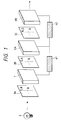
- Fig.1 is a schematic diagram showing the first basic optical system of the invention.
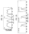
- Fig.2a and Fig.2b are schematic diagrams of transmission spectra for illustrating the principle of operation of the invention.
- Fig.3a and Fig.3b are schematic diagrams showing arrangements in the liquid crystal element for use in the first embodiment of the invention.
- Fig.4a and Fig.4b are schematic diagrams showing arrangements in the liquid crystal element for use in the second embodiment of the invention.
- Fig.5a and Fig.5b are schematic diagrams showing arrangement in the liquid crystal element for use in the third embodiment of the invention.
- Fig.6a and Fig.6b are schematic diagrams showing arrangement in the liquid crystal element for use in the fourth embodiment of the invention.
- Fig.7a and Fig.7b are schematic diagrams showing arrangement in the liquid crystal element for use in the fifth embodiment of the invention.
- Fig.8 is a schematic diagram illustrating the second basic optical system of the invention.
- Fig.9 is a schematic diagram illustrating the third basic optical system of the invention.
- Fig.1 shows the first basic constitution of one embodiment of the invention.
- the light emitted from white light source 5 is filtered by color polarizer 3A such that only green G and blue B which are polarization components in the vertical direction and only red R which is a polarization component in the horizontal direction are permitted to pass therethrough.
- each polarization component is modulated in response to an imaging signal sent from controller 41.
- the direction of linear polarization is rotated 90° ( ⁇ /2)
- a sufficient electrical field is applied, that is, at ON-state, each component is presumed to pass through without being changed of its polarization states.
- second color polarizer 3B has the same function as the first color polarizer 3A and is disposed in the same direction (normally black).
- the picture elements of the above active matrix-addressed liquid crystal element 1 are at OFF-state, the light cannot pass through the second color polarizer 3B as it is absorbed therein.
- the second color polarizer 3B when at ON-state, the light can pass therethrough, thus providing contrast between bright and dark. That is, images are displayed reflecting the intensity of light transmitted in response to an image signal from control unit 41.
- the second color polarizer 3B may be disposed by rotating 90° (normally white). In this case, the relations among bright, dark states and ON, OFF-states are reversed.
- the second and the third liquid crystals 2A and 2B finally select the spectra (hues) of light permitted to pass through this optical system. That is, the second liquid crystal cell basically over the whole surface of which electrodes have been formed, determines whether to transmit the light without changing the direction of polarization or rotate it by 90° by selecting whether to apply electric fields or not (i.e., ON or OFF).
- the third liquid crystal cell 2B has a function to select the direction of polarization of light passing therethrough according to its ON or OFF-states. For example, at OFF-state, only the polarized components in the vertical direction are permitted to pass through, and at ON-state, only the polarized components in the horizontal direction are permitted to pass through.
- third color polarizer 3C which has the same function, in principle, as the second and third color polarizers 3A and 3B, but imparts a combination of hues different from the above two to the light passing therethrough is disposed between the second and the third liquid crystal cells 2A and 2B. That is, only green G and red R, polarization components in the vertical direction are permitted to pass, while only blue B, polarization component in the horizontal direction is permitted to pass. At this time, combinations of ON and OFF-states for the second and the third liquid crystal elements 2A and 2B will impart different hues to light passing therethrough as shown in Table 1. Table 1 Second LC Element 2A Third LC Element 2B Hues of Light Transmitted OFF OFF Red(R) OFF ON Blue(B) ON OFF Green(G) ON ON --
- Fig.2a(a) and Fig.2a(b) diagrammatically show spectra of transmission light passing through two different color polarizers
- Fig.2b(c) to Fig.2b(e) diagrammatically show spectra of transmission light obtained when the liquid crystal cells 2A and 2B are operated.
- the modulation function by the second liquid crystal cell 2A, and the selection function of the third liquid crystal cell 2B there may be contemplated other combinations to the same effect as above, thereby it is to be understood that the present invention is not limited to the above-mentioned examples of the combination.
- TFT cells As an active-matrix cell can meet the requirement.
- TN liquid crystal cells or STN liquid crystal cells now in practical use, however, cannot meet the response time required for implementing the present invention.
- the first method to eliminate this problem it is proposed, when using the same TN display element as above, to make its twist angle relatively smaller (for example, about 60°), and also to make the thickness of a liquid crystal cell (i.e., the thickness of a liquid crystal layer) extremely thinner than the previous, for example, to be 3 ⁇ m which is about a half of the ordinary cell thickness.
- Fig.3 shows a schematic diagrammatical constitution of the same. Since the response time of liquid crystal cells is proportional to square of a cell's thickness d, the response time for the above is reduced to about one fourth, which is very advantageous for implementing the invention.
- the second method it is proposed to utilize a nematic liquid crystal which has an untwisted structure in its molecular orientation, and to make product of refractive index anisotropy ⁇ n of the liquid crystal and the cell's thickness d, i.e., ⁇ n x d to become 0.28 ⁇ m (Fig.4). If ⁇ n of a liquid crystal to be utilized is given by 0.1, d becomes 2.8 ⁇ m, which meets the requirements for the response time of the invention.
- the third method attempts to realize fast response while utilizing a nematic liquid crystal having the same orientation as the second method, and with a cell thickness comparable to those of the prior art cells.
- ferroelectric liquid crystals respond in less than 1 ms, thus they are most suitable to be used as the elements for the invention, in particular, as the second and the third liquid crystal elements.
- a display mode making use of birefringence (the fourth method, see Fig.6), or a guest-host mode utilizing a dichroic dye dispersion (the fifth method, see Fig.7) have been conceived.
- an antiferroelectric liquid crystal may be employed as the sixth method.
- the above-mentioned elements operating in the modes of the first through the six methods, except for the guest-host cell of the fifth method, may be provided with a so-called phase plate which causes the polarization states of transmission light to be changed. This is done to obtain a maximum contrast at an electrical field available in practice, because an electric field strength at which transmissivity becomes minimum can be shifted by incorporating the phase plate, as against a case, for example, of the second method where a very high voltage must be applied across the element to obtain a sufficient contrast for a display. Further, in the case of a ferroelectric liquid crystal cell corresponding to the above fourth method, the thickness of a cell can be controlled within a structure of ordinary ones.
- the first and the second liquid crystals have almost the same function. That is, they select by switching whether to rotate or not rotate the direction of polarization of an incident light by ⁇ /2.
- a difference between the above two liquid crystal cells lies simply in whether drive elements associated with picture elements of the display are formed in a matrix or not. Rotating the direction of polarization by ⁇ /2 can be attained through the use of the twisted structure, birefringence, or through a combined action of both.
- the third liquid crystal cell it is indispensable for the third liquid crystal cell, however, to have a function to select one from the two polarization states.
- a polarizer is necessary to be attached in its implementation.
- the fifth method as in this mode of operation, light is selectively absorbed with respect to the directions of polarization, no polarizer is required.
- this element is used as the second liquid crystal cell, it is necessary to provide a phase plate ( ⁇ /4 plate) at the emission side to obtain a nearly circular polarization of light.
- Fig.8 shows the second basic constitution of the invention.
- the first color polarizer 3A in the first basic constitution is replaced by linear polarizer 6.
- a display image at active-matrix liquid crystal cell 1 is reversed in contrast of bright and dark, associated with green (G) and blue (B), and red(R), with respect to ON and OFF-states in comparison with those in the first basic constitution.
- image signals from controller unit 41 must take into account the above reversion.
- Fig.9 shows the third basic constitution of another embodiment of the invention.
- the first liquid crystal cell 1 for image forming is a type which changes transmissivity of light itself (intensity modulation method) other than the incident light polarization state modulation method which has been described hereinabove
- color display is capable of being realized by such an arrangement as shown in Fig.9.
- liquid crystal cells suitable for the intensity modulation method there are, for example, polymer dispersed liquid crystals (PDLC). In an off-state where no electric field is applied, light is dispersed due to mismatching between refractive indexes of the liquid crystals and polymer matrices, whereas in an on-state, matching between them is attained thus inducing a transparent state therein.
- PDLC polymer dispersed liquid crystals
- Dichroic dye mixtures may be added into nematic liquid crystals to induce an enhanced contrast.
- nematic liquid crystal cells are partitioned in the polymer matrix in micron meter order, which enables obtaining a response speed of ms order suitable for realizing a preferred mode of display according to the invention.
- the functions assigned to two color polarizers, 3B and 3C, and those assigned to the second and the third liquid crystal elements 2A and 2B are the same with those assigned to in the foregoing first basic constitution.
- a color display is capable of being realized without the need of forming color filters in matrices corresponding to active matrix drive elements on the substrate. Furthermore, its display capacity can be enhanced threefold in principle as compared with prior arts, thus a high resolution display is capable of being realized.
- amorphous silicon transistors (hereinafter referred to as a-Si TFTs) were formed on a glass substrate as an active drive substrate in such a manner that upon completion of forming gate electrodes on a polished quartz glass substrate, an insulation layer (silicon nitride) and an a-Si layer were formed by the plasma CVD, then picture element electrodes (ITO electrodes), and finally source-drain electrodes were formed to complete the a-Si TFT.
- a glass substrate having ITO electrodes formed over the whole display area thereof was utilized.
- nematic liquid crystals of BDH Co. make E7 were mixed with a polyvinyl alcohol (about 500 degrees of polymerization) 10% water solution, and they were homogeneously mixed by rotation in a homogeneous mixer into emulsion which was taken out in a syringe onto the TFT substrates where it was applied thinly with a squeeger, then interposed between two opposing substrates to produce liquid crystal cells.
- liquid crystal cells Five different kinds were fabricated as the second and the third liquid crystal cells. In any of these cells, two glass substrates the whole display area of which was covered by ITO electrodes were utilized. The TN cell and the new ECB cell were arranged to have completely the same structure as the first liquid crystal cell except for the substrate. As the ECB cell, Merck Co. make MLC-1341 was used, the refractive index anisotropy of which was smaller than that of the liquid crystals used in the first liquid crystal cell. For its spacer, glass fiber with a 3 ⁇ m diameter was used.
- the Chisso Petro Chemical KK make CS-1026 was utilized for the former, while for the latter, a ferroelectric liquid crystal having the following composition was utilized mixed with about a 3 total weight percent of a dichroic pigment including appropriate amounts of Mitsubishi Kasei KK make LSY-116, LSR-401 and LSB-335.
- silica beads of a 1.8 ⁇ m diameter were used in the former, and glass fibers of 6 ⁇ m diameter were used in the latter case.
- a chromaticity diagram showed that each display performance of liquid crystal display devices having structures of No.1 through No.20 had a preferred color display capable of being realized by adopting the constitution of the invention.
Landscapes
- Physics & Mathematics (AREA)
- Nonlinear Science (AREA)
- Mathematical Physics (AREA)
- Chemical & Material Sciences (AREA)
- Crystallography & Structural Chemistry (AREA)
- General Physics & Mathematics (AREA)
- Optics & Photonics (AREA)
- Liquid Crystal (AREA)
Applications Claiming Priority (2)
| Application Number | Priority Date | Filing Date | Title |
|---|---|---|---|
| JP291213/91 | 1991-11-07 | ||
| JP3291213A JPH05127189A (ja) | 1991-11-07 | 1991-11-07 | カラー表示装置 |
Publications (1)
| Publication Number | Publication Date |
|---|---|
| EP0541128A1 true EP0541128A1 (de) | 1993-05-12 |
Family
ID=17765932
Family Applications (1)
| Application Number | Title | Priority Date | Filing Date |
|---|---|---|---|
| EP92119147A Withdrawn EP0541128A1 (de) | 1991-11-07 | 1992-11-09 | Farbiges Anzeigegerät |
Country Status (4)
| Country | Link |
|---|---|
| EP (1) | EP0541128A1 (de) |
| JP (1) | JPH05127189A (de) |
| KR (1) | KR930010587A (de) |
| CN (1) | CN1073267A (de) |
Cited By (4)
| Publication number | Priority date | Publication date | Assignee | Title |
|---|---|---|---|---|
| EP0638833A2 (de) * | 1993-08-14 | 1995-02-15 | Gec-Marconi Limited | Anzeigeanordnungen |
| EP0642150A1 (de) * | 1993-09-07 | 1995-03-08 | Sextant Avionique | Optimierte Farbanzeigevorrichtung |
| GB2308202A (en) * | 1995-12-15 | 1997-06-18 | Samsung Display Devices Co Ltd | Subtractive colour liquid crystal device |
| US5751483A (en) * | 1992-12-25 | 1998-05-12 | Mitsui Toatsu Chemicals, Inc. | Color filter having polarizability |
Families Citing this family (3)
| Publication number | Priority date | Publication date | Assignee | Title |
|---|---|---|---|---|
| KR100751191B1 (ko) * | 2000-12-29 | 2007-08-22 | 엘지.필립스 엘시디 주식회사 | 강유전성 액정표시장치및 그의 구동방법 |
| EP2273481A3 (de) * | 2001-06-11 | 2012-02-22 | Genoa Color Technologies Ltd. | Einrichtung, System und Verfahren für eine Farbanzeige |
| CN113448119A (zh) * | 2021-07-13 | 2021-09-28 | 深圳市兔高科技有限公司 | 液晶调光膜 |
Citations (4)
| Publication number | Priority date | Publication date | Assignee | Title |
|---|---|---|---|---|
| EP0237163A1 (de) * | 1986-02-05 | 1987-09-16 | Ford Motor Company Limited | Farbwählbares Flüssigkristall-Anzeigesystem |
| EP0274391A2 (de) * | 1987-01-09 | 1988-07-13 | Hitachi, Ltd. | Projektor mit Flüssigkristallzellen |
| EP0422687A1 (de) * | 1983-09-26 | 1991-04-17 | Tektronix, Inc. | Schaltbares Farbfilter |
| EP0451621A2 (de) * | 1990-04-12 | 1991-10-16 | Liesegang, Ed. | Flüssigkristallzellenanordnung |
-
1991
- 1991-11-07 JP JP3291213A patent/JPH05127189A/ja active Pending
-
1992
- 1992-11-06 CN CN92113770A patent/CN1073267A/zh active Pending
- 1992-11-07 KR KR1019920020862A patent/KR930010587A/ko not_active Application Discontinuation
- 1992-11-09 EP EP92119147A patent/EP0541128A1/de not_active Withdrawn
Patent Citations (4)
| Publication number | Priority date | Publication date | Assignee | Title |
|---|---|---|---|---|
| EP0422687A1 (de) * | 1983-09-26 | 1991-04-17 | Tektronix, Inc. | Schaltbares Farbfilter |
| EP0237163A1 (de) * | 1986-02-05 | 1987-09-16 | Ford Motor Company Limited | Farbwählbares Flüssigkristall-Anzeigesystem |
| EP0274391A2 (de) * | 1987-01-09 | 1988-07-13 | Hitachi, Ltd. | Projektor mit Flüssigkristallzellen |
| EP0451621A2 (de) * | 1990-04-12 | 1991-10-16 | Liesegang, Ed. | Flüssigkristallzellenanordnung |
Non-Patent Citations (2)
| Title |
|---|
| IBM TECHNICAL DISCLOSURE BULLETIN vol. 22, no. 5, October 1979, ARMONK, USA pages 1769 - 1772 A.N. BRINSON ET AL. 'Liquid Crystal Apparatus for Converting Black and White CRT Display into Colored Display' * |
| PATENT ABSTRACTS OF JAPAN vol. 15, no. 335 (P-1242)26 August 1991 & JP-A-31 25 121 ( STANLEY ELECTRIC ) 28 May 1991 * |
Cited By (8)
| Publication number | Priority date | Publication date | Assignee | Title |
|---|---|---|---|---|
| US5751483A (en) * | 1992-12-25 | 1998-05-12 | Mitsui Toatsu Chemicals, Inc. | Color filter having polarizability |
| EP0638833A2 (de) * | 1993-08-14 | 1995-02-15 | Gec-Marconi Limited | Anzeigeanordnungen |
| EP0638833A3 (de) * | 1993-08-14 | 1995-07-12 | Marconi Gec Ltd | Anzeigeanordnungen. |
| US5583674A (en) * | 1993-08-14 | 1996-12-10 | Gec-Marconi Ltd. | Multilayered display having two displays in series and a switchable optical retarder |
| EP0642150A1 (de) * | 1993-09-07 | 1995-03-08 | Sextant Avionique | Optimierte Farbanzeigevorrichtung |
| FR2709854A1 (fr) * | 1993-09-07 | 1995-03-17 | Sextant Avionique | Dispositif de visualisation à couleurs optimisées. |
| US5479279A (en) * | 1993-09-07 | 1995-12-26 | Sextant Avionique | Optimized color display device which uses a matrix to control the hue and uses a matrix to control color saturation |
| GB2308202A (en) * | 1995-12-15 | 1997-06-18 | Samsung Display Devices Co Ltd | Subtractive colour liquid crystal device |
Also Published As
| Publication number | Publication date |
|---|---|
| JPH05127189A (ja) | 1993-05-25 |
| KR930010587A (ko) | 1993-06-22 |
| CN1073267A (zh) | 1993-06-16 |
Similar Documents
| Publication | Publication Date | Title |
|---|---|---|
| JP3162210B2 (ja) | 液晶表示装置 | |
| JP2829149B2 (ja) | 液晶表示装置 | |
| KR100467819B1 (ko) | 액정표시장치 및 그 제조방법 | |
| US5986733A (en) | Negative optical compensator tilted in respect to liquid crystal cell for liquid crystal display | |
| US6184951B1 (en) | Liquid crystal display wherein each pixels of first layer is optically aligned with respective group of pixels of second layer | |
| JPH0572529A (ja) | 液晶表示素子及びそれを用いた装置とシステム | |
| JP2607741B2 (ja) | 液晶表示装置 | |
| JPH02176625A (ja) | 液晶表示装置 | |
| JPH0220A (ja) | カラー表示装置 | |
| EP0541128A1 (de) | Farbiges Anzeigegerät | |
| JP3683637B2 (ja) | 液晶表示装置 | |
| US6646710B2 (en) | Light modulator | |
| EP1151346B1 (de) | Anzeige mit achromatische verbundverzögerungsplatte | |
| Macknick et al. | High resolution displays using NCAP liquid crystals | |
| JP2767790B2 (ja) | 液晶電気光学装置の駆動方法 | |
| JPH1195206A (ja) | 偏光変換素子、液晶カラーシャッタ、カラー画像表示装置、および液晶セルの駆動方法 | |
| JP3449829B2 (ja) | 液晶表示素子 | |
| KR20080009818A (ko) | 액정 디스플레이 | |
| JPH04319914A (ja) | カラー液晶表示素子 | |
| JP2819670B2 (ja) | 液晶表示素子 | |
| JP3378038B2 (ja) | 電気光学装置の駆動方法 | |
| JPH08271934A (ja) | 液晶装置 | |
| JP2001142071A (ja) | 液晶表示装置 | |
| JPH03197923A (ja) | カラー液晶表示装置 | |
| KANEKO | Directly Addressed Matrix Liquid Crystal Display Panels with High Information Content |
Legal Events
| Date | Code | Title | Description |
|---|---|---|---|
| PUAI | Public reference made under article 153(3) epc to a published international application that has entered the european phase |
Free format text: ORIGINAL CODE: 0009012 |
|
| AK | Designated contracting states |
Kind code of ref document: A1 Designated state(s): CH DE FR GB LI |
|
| 17P | Request for examination filed |
Effective date: 19930517 |
|
| 17Q | First examination report despatched |
Effective date: 19941227 |
|
| STAA | Information on the status of an ep patent application or granted ep patent |
Free format text: STATUS: THE APPLICATION IS DEEMED TO BE WITHDRAWN |
|
| 18D | Application deemed to be withdrawn |
Effective date: 19950509 |