EP0540982A1 - Corner joint for hollow profiles of a window, door, facade or the like - Google Patents
Corner joint for hollow profiles of a window, door, facade or the like Download PDFInfo
- Publication number
- EP0540982A1 EP0540982A1 EP92118323A EP92118323A EP0540982A1 EP 0540982 A1 EP0540982 A1 EP 0540982A1 EP 92118323 A EP92118323 A EP 92118323A EP 92118323 A EP92118323 A EP 92118323A EP 0540982 A1 EP0540982 A1 EP 0540982A1
- Authority
- EP
- European Patent Office
- Prior art keywords
- corner connector
- profile
- extruded
- extruded profile
- connector according
- Prior art date
- Legal status (The legal status is an assumption and is not a legal conclusion. Google has not performed a legal analysis and makes no representation as to the accuracy of the status listed.)
- Granted
Links
Images

Classifications
-
- E—FIXED CONSTRUCTIONS
- E04—BUILDING
- E04B—GENERAL BUILDING CONSTRUCTIONS; WALLS, e.g. PARTITIONS; ROOFS; FLOORS; CEILINGS; INSULATION OR OTHER PROTECTION OF BUILDINGS
- E04B1/00—Constructions in general; Structures which are not restricted either to walls, e.g. partitions, or floors or ceilings or roofs
- E04B1/0046—Loggias
-
- E—FIXED CONSTRUCTIONS
- E04—BUILDING
- E04C—STRUCTURAL ELEMENTS; BUILDING MATERIALS
- E04C3/00—Structural elongated elements designed for load-supporting
- E04C3/02—Joists; Girders, trusses, or trusslike structures, e.g. prefabricated; Lintels; Transoms; Braces
- E04C3/04—Joists; Girders, trusses, or trusslike structures, e.g. prefabricated; Lintels; Transoms; Braces of metal
- E04C3/06—Joists; Girders, trusses, or trusslike structures, e.g. prefabricated; Lintels; Transoms; Braces of metal with substantially solid, i.e. unapertured, web
-
- E—FIXED CONSTRUCTIONS
- E04—BUILDING
- E04C—STRUCTURAL ELEMENTS; BUILDING MATERIALS
- E04C3/00—Structural elongated elements designed for load-supporting
- E04C3/38—Arched girders or portal frames
- E04C3/40—Arched girders or portal frames of metal
-
- E—FIXED CONSTRUCTIONS
- E06—DOORS, WINDOWS, SHUTTERS, OR ROLLER BLINDS IN GENERAL; LADDERS
- E06B—FIXED OR MOVABLE CLOSURES FOR OPENINGS IN BUILDINGS, VEHICLES, FENCES OR LIKE ENCLOSURES IN GENERAL, e.g. DOORS, WINDOWS, BLINDS, GATES
- E06B3/00—Window sashes, door leaves, or like elements for closing wall or like openings; Layout of fixed or moving closures, e.g. windows in wall or like openings; Features of rigidly-mounted outer frames relating to the mounting of wing frames
- E06B3/96—Corner joints or edge joints for windows, doors, or the like frames or wings
- E06B3/964—Corner joints or edge joints for windows, doors, or the like frames or wings using separate connection pieces, e.g. T-connection pieces
- E06B3/9644—L-shaped corner pieces having two articulated or flexible joined legs; Corner joints with variable angle
-
- E—FIXED CONSTRUCTIONS
- E06—DOORS, WINDOWS, SHUTTERS, OR ROLLER BLINDS IN GENERAL; LADDERS
- E06B—FIXED OR MOVABLE CLOSURES FOR OPENINGS IN BUILDINGS, VEHICLES, FENCES OR LIKE ENCLOSURES IN GENERAL, e.g. DOORS, WINDOWS, BLINDS, GATES
- E06B3/00—Window sashes, door leaves, or like elements for closing wall or like openings; Layout of fixed or moving closures, e.g. windows in wall or like openings; Features of rigidly-mounted outer frames relating to the mounting of wing frames
- E06B3/96—Corner joints or edge joints for windows, doors, or the like frames or wings
- E06B3/964—Corner joints or edge joints for windows, doors, or the like frames or wings using separate connection pieces, e.g. T-connection pieces
- E06B3/9645—Mitre joints
- E06B3/9646—Mitre joints using two similar connecting pieces each connected with one or the frame members and drawn together at the joint
-
- E—FIXED CONSTRUCTIONS
- E04—BUILDING
- E04C—STRUCTURAL ELEMENTS; BUILDING MATERIALS
- E04C3/00—Structural elongated elements designed for load-supporting
- E04C3/02—Joists; Girders, trusses, or trusslike structures, e.g. prefabricated; Lintels; Transoms; Braces
- E04C3/04—Joists; Girders, trusses, or trusslike structures, e.g. prefabricated; Lintels; Transoms; Braces of metal
- E04C2003/0404—Joists; Girders, trusses, or trusslike structures, e.g. prefabricated; Lintels; Transoms; Braces of metal beams, girders, or joists characterised by cross-sectional aspects
- E04C2003/0408—Joists; Girders, trusses, or trusslike structures, e.g. prefabricated; Lintels; Transoms; Braces of metal beams, girders, or joists characterised by cross-sectional aspects characterised by assembly or the cross-section
- E04C2003/0413—Joists; Girders, trusses, or trusslike structures, e.g. prefabricated; Lintels; Transoms; Braces of metal beams, girders, or joists characterised by cross-sectional aspects characterised by assembly or the cross-section being built up from several parts
- E04C2003/0417—Joists; Girders, trusses, or trusslike structures, e.g. prefabricated; Lintels; Transoms; Braces of metal beams, girders, or joists characterised by cross-sectional aspects characterised by assembly or the cross-section being built up from several parts demountable
-
- E—FIXED CONSTRUCTIONS
- E04—BUILDING
- E04C—STRUCTURAL ELEMENTS; BUILDING MATERIALS
- E04C3/00—Structural elongated elements designed for load-supporting
- E04C3/02—Joists; Girders, trusses, or trusslike structures, e.g. prefabricated; Lintels; Transoms; Braces
- E04C3/04—Joists; Girders, trusses, or trusslike structures, e.g. prefabricated; Lintels; Transoms; Braces of metal
- E04C2003/0404—Joists; Girders, trusses, or trusslike structures, e.g. prefabricated; Lintels; Transoms; Braces of metal beams, girders, or joists characterised by cross-sectional aspects
- E04C2003/0426—Joists; Girders, trusses, or trusslike structures, e.g. prefabricated; Lintels; Transoms; Braces of metal beams, girders, or joists characterised by cross-sectional aspects characterised by material distribution in cross section
- E04C2003/043—Joists; Girders, trusses, or trusslike structures, e.g. prefabricated; Lintels; Transoms; Braces of metal beams, girders, or joists characterised by cross-sectional aspects characterised by material distribution in cross section the hollow cross-section comprising at least one enclosed cavity
-
- E—FIXED CONSTRUCTIONS
- E04—BUILDING
- E04C—STRUCTURAL ELEMENTS; BUILDING MATERIALS
- E04C3/00—Structural elongated elements designed for load-supporting
- E04C3/02—Joists; Girders, trusses, or trusslike structures, e.g. prefabricated; Lintels; Transoms; Braces
- E04C3/04—Joists; Girders, trusses, or trusslike structures, e.g. prefabricated; Lintels; Transoms; Braces of metal
- E04C2003/0404—Joists; Girders, trusses, or trusslike structures, e.g. prefabricated; Lintels; Transoms; Braces of metal beams, girders, or joists characterised by cross-sectional aspects
- E04C2003/0443—Joists; Girders, trusses, or trusslike structures, e.g. prefabricated; Lintels; Transoms; Braces of metal beams, girders, or joists characterised by cross-sectional aspects characterised by substantial shape of the cross-section
- E04C2003/0465—Joists; Girders, trusses, or trusslike structures, e.g. prefabricated; Lintels; Transoms; Braces of metal beams, girders, or joists characterised by cross-sectional aspects characterised by substantial shape of the cross-section square- or rectangular-shaped
-
- E—FIXED CONSTRUCTIONS
- E04—BUILDING
- E04D—ROOF COVERINGS; SKY-LIGHTS; GUTTERS; ROOF-WORKING TOOLS
- E04D3/00—Roof covering by making use of flat or curved slabs or stiff sheets
- E04D3/02—Roof covering by making use of flat or curved slabs or stiff sheets of plane slabs, slates, or sheets, or in which the cross-section is unimportant
- E04D3/06—Roof covering by making use of flat or curved slabs or stiff sheets of plane slabs, slates, or sheets, or in which the cross-section is unimportant of glass or other translucent material; Fixing means therefor
- E04D3/08—Roof covering by making use of flat or curved slabs or stiff sheets of plane slabs, slates, or sheets, or in which the cross-section is unimportant of glass or other translucent material; Fixing means therefor with metal glazing bars
- E04D2003/0806—Roof covering by making use of flat or curved slabs or stiff sheets of plane slabs, slates, or sheets, or in which the cross-section is unimportant of glass or other translucent material; Fixing means therefor with metal glazing bars the supporting section of the glazing bar consisting of one single extruded or rolled metal part
-
- E—FIXED CONSTRUCTIONS
- E04—BUILDING
- E04D—ROOF COVERINGS; SKY-LIGHTS; GUTTERS; ROOF-WORKING TOOLS
- E04D3/00—Roof covering by making use of flat or curved slabs or stiff sheets
- E04D3/02—Roof covering by making use of flat or curved slabs or stiff sheets of plane slabs, slates, or sheets, or in which the cross-section is unimportant
- E04D3/06—Roof covering by making use of flat or curved slabs or stiff sheets of plane slabs, slates, or sheets, or in which the cross-section is unimportant of glass or other translucent material; Fixing means therefor
- E04D3/08—Roof covering by making use of flat or curved slabs or stiff sheets of plane slabs, slates, or sheets, or in which the cross-section is unimportant of glass or other translucent material; Fixing means therefor with metal glazing bars
- E04D2003/0868—Mutual connections and details of glazing bars
Definitions
- the invention relates to a corner connector with two at an angle to each other, insertable into hollow profiles with a rectangle circumscribed legs, which are designed as extruded sections with the same cross-section and the extruded sections have two parallel end faces produced by flat separating cuts, which under run at an angle ⁇ to the longitudinal axis of the profile and the extruded sections are inserted into one another "at the turn” and the end faces of both extruded sections intersect at an angle 2 ⁇ in pairs in a plane, in the area of which the contacting connecting surfaces of the two extruded sections lie.
- corner connectors are used for hollow profiles of a window, a door, a facade or a glass roof and veranda construction or the like. used.
- Corner connectors of this type are known (DE 36 32 154 C2), the two legs of which are cut from an extruded profile.
- This extruded profile has a profile forming the connecting surfaces on both narrow sides running parallel to the longitudinal axis of the profile.
- the profile of one narrow side is designed as a groove and that of the opposite narrow side as a tongue.
- the extruded profile is complex in construction due to the opposing profiling contours, which later have to ensure the required functions in terms of dimensions.
- the invention has for its object to design a corner connector of the type mentioned in such a way that the extruded profile from which the connector legs are cut is simpler in construction, the interlocking profiles are not influenced differently by the profile manufacturing conditions during the assembly of the corner connector, and that for the assembly of two extruded profile sections cut at the same angle, which form the corner connector legs, there is only one defined association with one another.
- This object is achieved in that a profile forming the connecting surfaces is provided only on a narrow side of the extruded profile running parallel to the longitudinal axis of the profile and the two extruded profile sections forming the legs of the corner connector can be positively assembled with the profiled narrow sides.
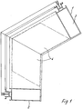
- the profile corner shown in FIG. 1 is composed of the hollow profiles 1, 2, which have a cavity 3 circumscribed by a rectangle, into which the legs 4 of a corner connector are inserted.
- the extruded profile 5 is shown in cross section, which has a profile 8 forming the connecting surfaces exclusively on a narrow side 7 running parallel to the longitudinal axis 6 of the profile, which in the embodiment according to FIG. 2 by two hook-shaped webs 9 and 10 and in which 5 is formed by hook-shaped webs 11 and 12.
- the profiling 8 is designed in such a way that a profile section can be inserted into this profiling when turned, i.e. turned by 180 ° about the longitudinal axis 6 of the profile.
- the hook-shaped webs 9 and 10 which run parallel to one another, delimit an inner groove 13.
- the other hook-shaped web 10 is designed as an edge web, the outer surface of which is aligned with the associated outer surface 15 of the extruded profile 5.
- the outer contour of the hook-shaped web 10 corresponds to the contour of an external groove 16 of the profiling, which is indicated in dash-dotted lines in FIG. 2 and is delimited inwards by the hook-shaped web 9.
- the extruded profile 5 shown in FIG. 4 is cut into several sections 17, 18 and 19 by several parallel cuts at an angle ⁇ to the longitudinal axis 6 of the profile.
- the profiles of these two extruded profile sections 18, 19 interlock and can be fixed using appropriate lanyards.
- the corner angle of the resulting corner connector is 2 ⁇ .
- the extruded profile 5 has a bore-shaped groove 22 which is open to the inner groove 13 and which extends in the longitudinal direction of the extruded profile 5 in the region of a hook strip 23 of the web 9.
- a further groove 24 is provided, which is also open to the inner groove 13 and is flat and circular in shape.
- the extruded profile 5 has welding bevels 26, 27 which, when plugged together, form two extruded profile sections forming a corner connector in the connecting joint, a welding groove 28 for welding the corner connector.
- shear-resistant connection of the two corner connector legs can alternatively take place by shear bolts 29 which are driven into corresponding bores 30 in the area of the profile hooking.
- the number of Shear bolts depend on the respective leg height of the corner connector.
- a bolt extending over the entire profile width can also be used, so that three shear planes result in terms of load.
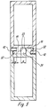
- FIG. 5 shows a further exemplary embodiment in which the profiling provided on a narrow side of the extruded profile is designed differently from the embodiment according to FIG. 2.
- the profiling has hook-shaped webs 11 and 12 which are not pushed into one another but are used against one another. This results in the assembled state of the two extruded sections between the internally arranged webs 11, a space 31 for receiving a bolt-shaped fastener for shear fixation of the connection.
- the space 31 has a width a, which thus corresponds to the distance between the webs 11 and is greater than the hooking incidence b of the web nose 32.
- the hook-shaped webs 11 have, on the side facing away from the web nose 32, circular-arc-shaped grooves 33 which form the guide of a screw bolt for fixing the connection.
- the web lugs 32 can have a slightly conical contour in order to ensure a play-free interlocking in the end position.
Abstract
Description
Die Erfindung bezieht sich auf einen Eckverbinder mit zwei unter einem Winkel zueinander stehenden, in Hohlprofile mit von einem Rechteck umschriebenen Hohlraum passend einschiebbaren Schenkeln, die als Strangprofilabschnitte mit gleichem Querschnitt ausgebildet sind und die Strangprofilabschnitte zwei parallele, durch ebene Trennschnitte erzeugte Endflächen aufweisen, die unter einem Winkel β zur Profillängsachse verlaufen und die Strangprofilabschnitte "auf Umschlag" ineinander eingesetzt sind und die Endflächen beider Strangprofilabschnitte sich unter einem Winkel 2 β paarweise in einer Ebene schneiden, in deren Bereich die sich berührenden Verbindungsflächen der beiden Strangprofilabschnitte liegen.The invention relates to a corner connector with two at an angle to each other, insertable into hollow profiles with a rectangle circumscribed legs, which are designed as extruded sections with the same cross-section and the extruded sections have two parallel end faces produced by flat separating cuts, which under run at an angle β to the longitudinal axis of the profile and the extruded sections are inserted into one another "at the turn" and the end faces of both extruded sections intersect at an
Diese Eckverbinder werden für Hohlprofile eines Fensters, einer Tür, einer Fassade oder einer Glasdach- sowie Verandakonstruktion o.dgl. eingesetzt.These corner connectors are used for hollow profiles of a window, a door, a facade or a glass roof and veranda construction or the like. used.
Es sind Eckverbinder dieser Art bekannt (DE 36 32 154 C2), deren beide Schenkel aus einem Strangpreßprofil geschnitten werden. Dieses Strangpreßprofil weist an beiden parallel zur Profillängsachse verlaufenden Schmalseiten eine die Verbindungsflächen bildende Profilierung auf. Die Profilierung der einen Schmalseite ist als Nut und die der gegenüberliegenden Schmalseite als Feder gestaltet. Durch Zusammenfügen von Nut und Feder der Strangprofilabschnitte, die die Schenkel des Eckverbinders bilden, wird der Eckverbinder hergestellt.Corner connectors of this type are known (DE 36 32 154 C2), the two legs of which are cut from an extruded profile. This extruded profile has a profile forming the connecting surfaces on both narrow sides running parallel to the longitudinal axis of the profile. The profile of one narrow side is designed as a groove and that of the opposite narrow side as a tongue. By merging The tongue and groove of the extruded sections that form the legs of the corner connector, the corner connector is made.
Das Strangpreßprofil ist durch die gegenüberliegenden Profilierungskonturen, die im späteren Zusammenwirken maßlich die erforderlichen Funktionen sicherstellen müssen, im Aufbau aufwendig.The extruded profile is complex in construction due to the opposing profiling contours, which later have to ensure the required functions in terms of dimensions.
Auch beim Pressen des Strangprofils können sich unterschiedliche Toleranzeinflüsse an der Nut- oder an der Federseite des Strangprofils ergeben, die das spätere Zusammenwirken der beiden Profilierungen beeinträchtigen können.Even when pressing the extruded profile, different tolerance influences can arise on the tongue or tongue side of the extruded profile, which can impair the later interaction of the two profiles.
Ein weiterer Nachteil ergibt sich daraus, daß nach dem Zuschneiden der Strangprofilabschnitte die Möglichkeit des unterschiedlichen Zusammenschiebens der beiden Bauteile gegeben ist.Another disadvantage arises from the fact that after the extruded sections have been cut to size, the two components can be pushed together differently.
Der Erfindung liegt die Aufgabe zugrunde, einen Eckverbinder der eingangs genannten Art so zu gestalten, daß das Strangpreßprofil, aus dem die Verbinderschenkel geschnitten werden, einfacher in der Konstruktion ist, die bei der Montage des Eckverbinders ineinandergreifenden Profilierungen durch die Profilherstellbedingungen nicht unterschiedlich beeinflußt sind, und daß es für das Zusammensetzen zweier, unter gleichem Winkel geschnittener Strangprofilabschnitte, die die Eckverbinderschenkel bilden, nur eine definierte Zuordnung zueinander gibt.The invention has for its object to design a corner connector of the type mentioned in such a way that the extruded profile from which the connector legs are cut is simpler in construction, the interlocking profiles are not influenced differently by the profile manufacturing conditions during the assembly of the corner connector, and that for the assembly of two extruded profile sections cut at the same angle, which form the corner connector legs, there is only one defined association with one another.
Diese Aufgabe wird erfindungsgemäß dadurch gelöst, daß ausschließlich an einer parallel zur Profillängsachse verlaufenden Schmalseite des Strangprofils eine die Verbindungsflächen bildende Profilierung vorgesehen ist und die beiden die Schenkel des Eckverbinders bildenden Strangprofilabschnitte mit den profilierten Schmalseiten formschlüssig zusammensetzbar sind.This object is achieved in that a profile forming the connecting surfaces is provided only on a narrow side of the extruded profile running parallel to the longitudinal axis of the profile and the two extruded profile sections forming the legs of the corner connector can be positively assembled with the profiled narrow sides.
Da das Strangpreßprofil, aus dem die Eckverbinderschenkel geschnitten werden, ausschließlich an einer parallel zur Profillängsachse verlaufenden Schmalseite eine die Verbindungsflächen zweier Eckverbinderschenkel bildende Profilierung aufweist, ergeben sich ein einfacher Gesamtaufbau des Strangpreßprofils sowie übereinstimmende Herstellbedingungen für die Profilierungen.Since the extruded profile from which the corner connector legs are cut, only on a parallel to the longitudinal axis of the profile Narrow side has a profile forming the connecting surfaces of two corner connector legs, there is a simple overall structure of the extruded profile and matching manufacturing conditions for the profiles.
Weitere Merkmale der Erfindung ergeben sich aus den Unteransprüchen.Further features of the invention emerge from the subclaims.
Ausführungsbeispiele der Erfindung sind in den Zeichnungen dargestellt und werden im folgenden beschrieben.Embodiments of the invention are shown in the drawings and are described below.
Es zeigen:
- Fig. 1
- eine Profilecke, die einen beliebigen Winkel haben kann, mit eingesetztem Eckverbinder,
- Fig. 2
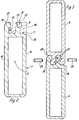
- das Strangpreßprofil im Querschnitt, aus dem die die Verbinderschenkel bildenden Strangprofilabschnitte geschnitten werden,
- Fig. 3
- die formschlüssige Verbindung zweier Profilabschnitte im Schnitt,
- Fig. 4
- das Strangprofil, das mittels paralleler Schnitte unter einem Winkel, der dem späteren halben Eckwinkel entspricht, in mehrere Abschnitte geschnitten ist sowie die Montage eines Eckverbinders und
- Fig. 5
- eine Abwandlungsform einer formschlüssigen Verbindung zweier Profilabschnitte.
- Fig. 1
- a profile corner, which can have any angle, with inserted corner connector,
- Fig. 2
- the extruded profile in cross section from which the extruded profile sections forming the connector legs are cut,
- Fig. 3
- the positive connection of two profile sections in the cut,
- Fig. 4
- the extruded profile, which is cut into several sections by means of parallel cuts at an angle which corresponds to the later half corner angle, and the assembly of a corner connector and
- Fig. 5
- a modification of a positive connection between two profile sections.
Die in der Fig. 1 aufgezeigte Profilecke setzt sich aus den Hohlprofilen 1,2 zusammen, die einen von einem Rechteck umschriebenen Hohlraum 3 aufweisen, in den die Schenkel 4 eines Eckverbinders eingeschoben werden. Die Schenkel 4, die als Strangprofilabschnitte mit gleichem Querschnitt ausgebildet sind, füllen in ihrem Bereich den Hohlraum 3 aus.The profile corner shown in FIG. 1 is composed of the
In der Fig. 2 ist das Strangprofil 5 im Querschnitt dargestellt, das ausschließlich an einer parallel zur Profillängsachse 6 verlaufenden Schmalseite 7 eine die Verbindungsflächen bildende Profilierung 8 aufweist, die beim Ausführungsbeispiel nach der Fig. 2 durch zwei hakenförmige Stege 9 und 10 und bei dem Ausführungsbeispiel nach der Fig. 5 durch hakenförmige Stege 11 und 12 gebildet wird.2, the
Bei dem Strangprofil 5 nach der Fig. 2 ist die Profilierung 8 so ausgebildet, daß ein Profilabschnitt auf Umschlag, d.h., um 180° um die Profillängsachse 6 gedreht in diese Profilierung eingeschoben werden kann.In the
Die Kombination zweier Profilabschnitte 4 zu einem Eckverbinder ist in der Fig. 3 aufgezeigt.The combination of two profile sections 4 to form a corner connector is shown in FIG. 3.
Bei der Profilierung 8 nach der Fig. 2 begrenzen die hakenförmigen Stege 9 und 10, die zueinander parallel verlaufen, eine Innennut 13. Der gegenüber der Außenfläche 14 des Strangprofils 5 nach innen versetzte hakenförmige Steg 9 entspricht in seiner äußeren Kontur der Kontur der Innennut 13. Der andere hakenförmige Steg 10 ist als Randsteg ausgebildet, dessen Außenfläche mit der zugeordneten Außenfläche 15 des Strangprofils 5 fluchtet.2, the hook-
Der hakenförmige Steg 10 entspricht in seiner äußeren Kontur der Kontur einer Außennut 16 der Profilierung, die in der Fig. 2 in strichpunktierten Linien angegeben ist und nach innen durch den hakenförmigen Steg 9 begrenzt wird.The outer contour of the hook-
Das in der Fig. 4 dargestellte Strangprofil 5 ist durch mehrere parallele Schnitte unter einem Winkel β zur Profillängsachse 6 in mehrere Abschnitte 17,18 und 19 geschnitten. Durch Schwenken des Strangprofilabschnittes 18 in die Position 18.1 und durch Verschieben in Richtung der Profillängsachse 6 bzw. des Pfeiles 20 in die Position 18.2 greifen die Profilierungen dieser beiden Strangprofilabschnitte 18,19 ineinander und können durch entsprechende Verbindungsmittel fixiert werden.The
Der Eckwinkel des entstandenen Eckverbinders beträgt 2 β .The corner angle of the resulting corner connector is 2 β.
Durch das Zusammenschieben der beiden Strangprofilabschnitte 19 und 18.2 ergibt sich ein Überstand 21 eines Strangprofilabschnittes, der anschließend nachzuarbeiten ist.By pushing the two
Nach dem Zuschneiden zweier Strangprofilabschnitte gibt es nur eine einzige Position, in der beide Strangprofilabschnitte ineinandergefügt werden können.After cutting two extruded sections, there is only one position in which both extruded sections can be joined together.
Das Strangprofil 5 verfügt über eine zur Innennut 13 geöffnete, bohrungsförmige Nut 22, die sich in Längsrichtung des Strangprofils 5 im Bereich einer Hakenleiste 23 des Stegs 9 erstreckt. Im Fußbereich des Steges 9 ist eine weitere Nut 24 vorgesehen, die ebenfalls zur Innennut 13 geöffnet ist und flach und kreisbogenförmig ausgebildet ist.The
Sofern zwei zugeschnittene Strangprofilabschnitte ineinandergeschoben werden, um einen Eckverbinder zu bilden, fluchten die Nuten 22 und 24 der benachbart liegenden hakenförmigen Stege 9 miteinander, so daß sich zwei Schraubkanäle 25 ergeben, die je nach den Erfordernissen der Belastung des jeweiligen Eckverbinders mit Sicherungsschrauben versehen werden können, um den Verschub in der Trennebene zu unterbinden.If two cut extruded profile sections are pushed together to form a corner connector, the
Ferner verfügt das Strangprofil 5 über Schweißfasen 26,27, die in zusammengestecktem Zustand von zwei einen Eckverbinder bildenden Strangprofilabschnitten in der Verbindungsfuge eine Schweißkehle 28 zum Verschweißen des Eckverbinders bilden.Furthermore, the
Die schubfeste Verbindung der beiden Eckverbinderschenkel kann alternativ durch Scherbolzen 29 erfolgen, die in entsprechende Bohrungen 30 im Bereich der Profilverhakung eingeschlagen werden. Die Anzahl der Scherbolzen richtet sich nach der jeweiligen Schenkelhöhe des Eckverbinders.The shear-resistant connection of the two corner connector legs can alternatively take place by
Anstelle zweier Scherbolzen kann auch ein sich über die gesamte Profilbreite erstreckender Bolzen verwendet werden, so daß sich belastungsmäßig drei Scherebenen ergeben.Instead of two shear bolts, a bolt extending over the entire profile width can also be used, so that three shear planes result in terms of load.
Die Fig. 5 zeigt ein weiteres Ausführungsbeispiel, bei dem die an einer Schmalseite des Strangprofils vorgesehene Profilierung abweichend gegenüber der Ausführung nach der Fig. 2 gestaltet ist.FIG. 5 shows a further exemplary embodiment in which the profiling provided on a narrow side of the extruded profile is designed differently from the embodiment according to FIG. 2.
Die Profilierung weist hakenförmige Stege 11 und 12 auf, die nicht ineinandergeschoben sondern gegeneinander eingesetzt werden. Hierbei ergibt sich in zusammengesetztem Zustand der beiden Strangprofilabschnitte zwischen den innen angeordneten Stegen 11 ein Raum 31 zur Aufnahme eines bolzenförmigen Befestigungsmittels zur Schubfixierung der Verbindung. Der Raum 31 weist eine Breite a auf, die somit dem Abstand der Stege 11 entspricht und größer ist als der Verhakungseinstand b der Stegnase 32.The profiling has hook-
Die hakenförmigen Stege 11 weisen an der der Stegnase 32 abgewandten Seite kreisbogenabschnittsförmige Nuten 33 auf, die die Führung eines Schraubbolzens zur Fixierung der Verbindung bilden.The hook-
Die Stegnasen 32 können eine leicht konische Kontur aufweisen, um in der Endposition eine spielfreie Verhakung zu sichern.The
Bei dieser Ausführungsform ist sichergestellt, daß die maßliche Zuordnung der Verhakungsprofilierung immer gegeben ist, daß das Extrusionswerkzeug und die Herstellung des Strangprofils vereinfacht wird und daß eine eindeutige Handhabung der Strangprofilabschnitte beim Zusammenstecken zu einem Eckverbinder vorgegeben ist.In this embodiment it is ensured that the dimensional assignment of the interlocking profile is always given, that the extrusion tool and the production of the extruded profile is simplified and that the extruded profile sections are clearly handled when they are plugged together to form a corner connector.
- 11
- HohlprofilHollow profile
- 22nd
- HohlprofilHollow profile
- 33rd
- Hohlraumcavity
- 44th
- Schenkelleg
- 55
- StrangprofilExtruded profile
- 66
- ProfillängsachseProfile longitudinal axis
- 77
- SchmalseiteNarrow side
- 88th
- ProfilierungProfiling
- 99
- Stegweb
- 1010th
- Stegweb
- 1111
- Stegweb
- 1212
- Stegweb
- 1313
- InnennutInner groove
- 1414
- AußenflächeOutside surface
- 1515
- AußenflächeOutside surface
- 1616
- AußennutExternal groove
- 1717th
- Abschnittsection
- 1818th
- Abschnittsection
- 1919th
- Abschnittsection
- 2020th
- Pfeilarrow
- 2121
- ÜberstandGot over
- 2222
- NutGroove
- 2323
- HakenleisteHook bar
- 2424th
- NutGroove
- 2525th
- SchraubkanalScrew channel
- 2626
- SchweißfaseWelding bevel
- 2727
- SchweißfaseWelding bevel
- 2828
- SchweißkehleWeld throat
- 2929
- ScherbolzenShear bolt
- 3030th
- Bohrungdrilling
- 3131
- Raumroom
- 3232
- StegnaseBridge nose
- 3333
- NutGroove
Claims (12)
Applications Claiming Priority (2)
| Application Number | Priority Date | Filing Date | Title |
|---|---|---|---|
| DE4136499 | 1991-11-06 | ||
| DE4136499A DE4136499A1 (en) | 1991-11-06 | 1991-11-06 | CORNER CONNECTOR FOR HOLLOW PROFILES OF A WINDOW, DOOR, FACADE OR THE LIKE |
Publications (2)
| Publication Number | Publication Date |
|---|---|
| EP0540982A1 true EP0540982A1 (en) | 1993-05-12 |
| EP0540982B1 EP0540982B1 (en) | 1994-09-07 |
Family
ID=6444180
Family Applications (1)
| Application Number | Title | Priority Date | Filing Date |
|---|---|---|---|
| EP92118323A Expired - Lifetime EP0540982B1 (en) | 1991-11-06 | 1992-10-27 | Corner joint for hollow profiles of a window, door, facade or the like |
Country Status (6)
| Country | Link |
|---|---|
| EP (1) | EP0540982B1 (en) |
| AT (1) | ATE111184T1 (en) |
| DE (2) | DE4136499A1 (en) |
| DK (1) | DK0540982T3 (en) |
| ES (1) | ES2059186T3 (en) |
| FI (1) | FI98648C (en) |
Cited By (2)
| Publication number | Priority date | Publication date | Assignee | Title |
|---|---|---|---|---|
| WO1999046456A1 (en) * | 1998-03-12 | 1999-09-16 | Ultraframe (Uk) Limited | Portals |
| WO2008128507A1 (en) * | 2007-04-19 | 2008-10-30 | Conergy Ag | Connectable profiled mounting rail (base rail) |
Families Citing this family (1)
| Publication number | Priority date | Publication date | Assignee | Title |
|---|---|---|---|---|
| CN104234585A (en) * | 2014-08-01 | 2014-12-24 | 浙江瑞明节能科技股份有限公司 | Door and window integrated type 90-degree corner structure |
Citations (1)
| Publication number | Priority date | Publication date | Assignee | Title |
|---|---|---|---|---|
| DE3632154C2 (en) * | 1986-09-22 | 1990-02-08 | Siegfried 6074 Roedermark De Kraus |
-
1991
- 1991-11-06 DE DE4136499A patent/DE4136499A1/en not_active Withdrawn
-
1992
- 1992-10-27 ES ES92118323T patent/ES2059186T3/en not_active Expired - Lifetime
- 1992-10-27 DK DK92118323.2T patent/DK0540982T3/en active
- 1992-10-27 AT AT92118323T patent/ATE111184T1/en not_active IP Right Cessation
- 1992-10-27 EP EP92118323A patent/EP0540982B1/en not_active Expired - Lifetime
- 1992-10-27 DE DE59200470T patent/DE59200470D1/en not_active Expired - Fee Related
- 1992-11-05 FI FI925014A patent/FI98648C/en active
Patent Citations (1)
| Publication number | Priority date | Publication date | Assignee | Title |
|---|---|---|---|---|
| DE3632154C2 (en) * | 1986-09-22 | 1990-02-08 | Siegfried 6074 Roedermark De Kraus |
Cited By (4)
| Publication number | Priority date | Publication date | Assignee | Title |
|---|---|---|---|---|
| WO1999046456A1 (en) * | 1998-03-12 | 1999-09-16 | Ultraframe (Uk) Limited | Portals |
| WO2008128507A1 (en) * | 2007-04-19 | 2008-10-30 | Conergy Ag | Connectable profiled mounting rail (base rail) |
| US8091847B2 (en) | 2007-04-19 | 2012-01-10 | Mounting Systems Gmbh | Connectable profiled mounting rail (base rail) |
| CN101711331B (en) * | 2007-04-19 | 2012-08-01 | 安装系统有限公司 | Connectable profiled mounting rail (base rail) |
Also Published As
| Publication number | Publication date |
|---|---|
| FI98648B (en) | 1997-04-15 |
| ES2059186T3 (en) | 1994-11-01 |
| EP0540982B1 (en) | 1994-09-07 |
| FI925014A (en) | 1993-05-07 |
| DK0540982T3 (en) | 1994-10-17 |
| FI925014A0 (en) | 1992-11-05 |
| DE59200470D1 (en) | 1994-10-13 |
| ATE111184T1 (en) | 1994-09-15 |
| DE4136499A1 (en) | 1993-05-13 |
| FI98648C (en) | 1997-07-25 |
Similar Documents
| Publication | Publication Date | Title |
|---|---|---|
| EP0006431B1 (en) | Hollow building panel of extruded plastics | |
| EP0652332B1 (en) | Heat insulating panel made of fibrous insulating material or cork | |
| EP0220389B1 (en) | Panel to cover walls or ceilings | |
| EP1352134B1 (en) | Transom-mullion structure | |
| EP0452256A1 (en) | Angular connection of two profiles with a C-shaped prolongation using a connector and an angular element for assembling the connection | |
| DE1927040A1 (en) | Link for assembling aluminum or the like extruded profiles | |
| DE2147623A1 (en) | Flat surface formed from metal planks | |
| WO1995033901A1 (en) | Façade construction for buildings | |
| DE2800811A1 (en) | Extruded transparent plastics window effect box panel - has end protrusion and groove section with filling for sealed interlocking | |
| EP1596022A2 (en) | Pressure bar for a building facade or a roof | |
| DE2610466C2 (en) | Isolation profile for a heat-insulating aluminum profile | |
| DE4331963A1 (en) | Arrangement for the detachable fastening of preferably flat elements in a system formed by posts and transoms | |
| EP0540982B1 (en) | Corner joint for hollow profiles of a window, door, facade or the like | |
| EP2186959B1 (en) | T-connection between a profiled post and profiled transom | |
| DE2235392A1 (en) | PROFILE BAR SYSTEM FOR METAL WINDOWS AND DOORS | |
| EP0799945A1 (en) | Construction of mullions and transoms | |
| EP0960985A2 (en) | I-section girder for building constructions | |
| EP0261532A1 (en) | Corner joining device for hollow-profile members | |
| DE3809988C2 (en) | Structural bar-shaped component | |
| EP0111185A2 (en) | Frame, in particular for a partition wall of a shower | |
| DE19740461C2 (en) | Method and connection system for the permanent connection of profiles or profile elements | |
| EP1491696A2 (en) | System for joining profiles | |
| DE3301324A1 (en) | IMPROVEMENTS OF FRAME PARTS FOR WINDOWS, DOORS AND OTHER FRAME CONSTRUCTIONS | |
| EP0125473A2 (en) | Insulating bar for heat-insulated composite frame members for windows, doors or façades and method of inserting said insulating bar | |
| DE2440794A1 (en) | Sectional metal or synthetic material bar - components, groove and spring connection via wedges and counter wedges |
Legal Events
| Date | Code | Title | Description |
|---|---|---|---|
| PUAI | Public reference made under article 153(3) epc to a published international application that has entered the european phase |
Free format text: ORIGINAL CODE: 0009012 |
|
| AK | Designated contracting states |
Kind code of ref document: A1 Designated state(s): AT CH DE DK ES FR GB IT LI NL |
|
| 17P | Request for examination filed |
Effective date: 19930407 |
|
| 17Q | First examination report despatched |
Effective date: 19931102 |
|
| ITF | It: translation for a ep patent filed |
Owner name: STUDIO INGG. FISCHETTI & WEBER |
|
| GRAA | (expected) grant |
Free format text: ORIGINAL CODE: 0009210 |
|
| AK | Designated contracting states |
Kind code of ref document: B1 Designated state(s): AT CH DE DK ES FR GB IT LI NL |
|
| REF | Corresponds to: |
Ref document number: 111184 Country of ref document: AT Date of ref document: 19940915 Kind code of ref document: T |
|
| GBT | Gb: translation of ep patent filed (gb section 77(6)(a)/1977) |
Effective date: 19940913 |
|
| REF | Corresponds to: |
Ref document number: 59200470 Country of ref document: DE Date of ref document: 19941013 |
|
| REG | Reference to a national code |
Ref country code: DK Ref legal event code: T3 |
|
| ET | Fr: translation filed | ||
| REG | Reference to a national code |
Ref country code: ES Ref legal event code: FG2A Ref document number: 2059186 Country of ref document: ES Kind code of ref document: T3 |
|
| PLBE | No opposition filed within time limit |
Free format text: ORIGINAL CODE: 0009261 |
|
| STAA | Information on the status of an ep patent application or granted ep patent |
Free format text: STATUS: NO OPPOSITION FILED WITHIN TIME LIMIT |
|
| 26N | No opposition filed | ||
| REG | Reference to a national code |
Ref country code: GB Ref legal event code: IF02 |
|
| PGFP | Annual fee paid to national office [announced via postgrant information from national office to epo] |
Ref country code: ES Payment date: 20051014 Year of fee payment: 14 |
|
| PGFP | Annual fee paid to national office [announced via postgrant information from national office to epo] |
Ref country code: DK Payment date: 20051026 Year of fee payment: 14 |
|
| PG25 | Lapsed in a contracting state [announced via postgrant information from national office to epo] |
Ref country code: DK Free format text: LAPSE BECAUSE OF NON-PAYMENT OF DUE FEES Effective date: 20061031 |
|
| PGFP | Annual fee paid to national office [announced via postgrant information from national office to epo] |
Ref country code: IT Payment date: 20061031 Year of fee payment: 15 |
|
| REG | Reference to a national code |
Ref country code: CH Ref legal event code: PCAR Free format text: ISLER & PEDRAZZINI AG;POSTFACH 1772;8027 ZUERICH (CH) |
|
| REG | Reference to a national code |
Ref country code: ES Ref legal event code: FD2A Effective date: 20061028 |
|
| PG25 | Lapsed in a contracting state [announced via postgrant information from national office to epo] |
Ref country code: ES Free format text: LAPSE BECAUSE OF NON-PAYMENT OF DUE FEES Effective date: 20061028 |
|
| PGFP | Annual fee paid to national office [announced via postgrant information from national office to epo] |
Ref country code: NL Payment date: 20081023 Year of fee payment: 17 |
|
| PGFP | Annual fee paid to national office [announced via postgrant information from national office to epo] |
Ref country code: CH Payment date: 20081027 Year of fee payment: 17 Ref country code: DE Payment date: 20081024 Year of fee payment: 17 |
|
| PGFP | Annual fee paid to national office [announced via postgrant information from national office to epo] |
Ref country code: AT Payment date: 20081023 Year of fee payment: 17 |
|
| PGFP | Annual fee paid to national office [announced via postgrant information from national office to epo] |
Ref country code: FR Payment date: 20081021 Year of fee payment: 17 |
|
| PGFP | Annual fee paid to national office [announced via postgrant information from national office to epo] |
Ref country code: GB Payment date: 20081024 Year of fee payment: 17 |
|
| PG25 | Lapsed in a contracting state [announced via postgrant information from national office to epo] |
Ref country code: IT Free format text: LAPSE BECAUSE OF NON-PAYMENT OF DUE FEES Effective date: 20071027 |
|
| REG | Reference to a national code |
Ref country code: NL Ref legal event code: V1 Effective date: 20100501 |
|
| REG | Reference to a national code |
Ref country code: CH Ref legal event code: PL |
|
| REG | Reference to a national code |
Ref country code: FR Ref legal event code: ST Effective date: 20100630 |
|
| PG25 | Lapsed in a contracting state [announced via postgrant information from national office to epo] |
Ref country code: DE Free format text: LAPSE BECAUSE OF NON-PAYMENT OF DUE FEES Effective date: 20100501 Ref country code: FR Free format text: LAPSE BECAUSE OF NON-PAYMENT OF DUE FEES Effective date: 20091102 Ref country code: NL Free format text: LAPSE BECAUSE OF NON-PAYMENT OF DUE FEES Effective date: 20100501 |
|
| PG25 | Lapsed in a contracting state [announced via postgrant information from national office to epo] |
Ref country code: AT Free format text: LAPSE BECAUSE OF NON-PAYMENT OF DUE FEES Effective date: 20091027 |
|
| PG25 | Lapsed in a contracting state [announced via postgrant information from national office to epo] |
Ref country code: CH Free format text: LAPSE BECAUSE OF NON-PAYMENT OF DUE FEES Effective date: 20091031 Ref country code: LI Free format text: LAPSE BECAUSE OF NON-PAYMENT OF DUE FEES Effective date: 20091031 |
|
| PG25 | Lapsed in a contracting state [announced via postgrant information from national office to epo] |
Ref country code: GB Free format text: LAPSE BECAUSE OF NON-PAYMENT OF DUE FEES Effective date: 20091027 |