EP0540316B1 - Procédé de codage - Google Patents
Procédé de codage Download PDFInfo
- Publication number
- EP0540316B1 EP0540316B1 EP92309882A EP92309882A EP0540316B1 EP 0540316 B1 EP0540316 B1 EP 0540316B1 EP 92309882 A EP92309882 A EP 92309882A EP 92309882 A EP92309882 A EP 92309882A EP 0540316 B1 EP0540316 B1 EP 0540316B1
- Authority
- EP
- European Patent Office
- Prior art keywords
- group
- status
- tape
- symbol
- units
- Prior art date
- Legal status (The legal status is an assumption and is not a legal conclusion. Google has not performed a legal analysis and makes no representation as to the accuracy of the status listed.)
- Expired - Lifetime
Links
Images


Classifications
-
- G—PHYSICS
- G11—INFORMATION STORAGE
- G11B—INFORMATION STORAGE BASED ON RELATIVE MOVEMENT BETWEEN RECORD CARRIER AND TRANSDUCER
- G11B20/00—Signal processing not specific to the method of recording or reproducing; Circuits therefor
- G11B20/10—Digital recording or reproducing
- G11B20/18—Error detection or correction; Testing, e.g. of drop-outs
- G11B20/1833—Error detection or correction; Testing, e.g. of drop-outs by adding special lists or symbols to the coded information
-
- G—PHYSICS
- G11—INFORMATION STORAGE
- G11B—INFORMATION STORAGE BASED ON RELATIVE MOVEMENT BETWEEN RECORD CARRIER AND TRANSDUCER
- G11B20/00—Signal processing not specific to the method of recording or reproducing; Circuits therefor
- G11B20/10—Digital recording or reproducing
- G11B20/12—Formatting, e.g. arrangement of data block or words on the record carriers
- G11B20/1201—Formatting, e.g. arrangement of data block or words on the record carriers on tapes
- G11B20/1202—Formatting, e.g. arrangement of data block or words on the record carriers on tapes with longitudinal tracks only
- G11B20/1205—Formatting, e.g. arrangement of data block or words on the record carriers on tapes with longitudinal tracks only for discontinuous data, e.g. digital information signals, computer programme data
-
- G—PHYSICS
- G11—INFORMATION STORAGE
- G11B—INFORMATION STORAGE BASED ON RELATIVE MOVEMENT BETWEEN RECORD CARRIER AND TRANSDUCER
- G11B27/00—Editing; Indexing; Addressing; Timing or synchronising; Monitoring; Measuring tape travel
- G11B27/10—Indexing; Addressing; Timing or synchronising; Measuring tape travel
- G11B27/19—Indexing; Addressing; Timing or synchronising; Measuring tape travel by using information detectable on the record carrier
- G11B27/28—Indexing; Addressing; Timing or synchronising; Measuring tape travel by using information detectable on the record carrier by using information signals recorded by the same method as the main recording
- G11B27/32—Indexing; Addressing; Timing or synchronising; Measuring tape travel by using information detectable on the record carrier by using information signals recorded by the same method as the main recording on separate auxiliary tracks of the same or an auxiliary record carrier
-
- G—PHYSICS
- G11—INFORMATION STORAGE
- G11B—INFORMATION STORAGE BASED ON RELATIVE MOVEMENT BETWEEN RECORD CARRIER AND TRANSDUCER
- G11B2220/00—Record carriers by type
- G11B2220/90—Tape-like record carriers
Definitions
- This invention relates generally to dynamic storage devices and more particularly to a format for encoding, sensing and correcting data representing an identifier for a volume of data information and to a process for controlling a data processing system to accomplish same to permit the reliable sensing of encoded data encoded on media having different track densities.
- Modern tape drive systems use a reel-to-reel drive to move a tape back and forth in close proximity to one or more read and/or write transducing heads.
- a leader block attached to the longitudinal end of the tape is automatically threaded through the tape path and the tape is spooled upon the take-up reel.
- the length of tape wound upon the supply reel is determined using tachometers on the supply and take-up reels. The tachometers are used to measure the amount of rotation of such reels during a specified period.
- the amount of rotation of the supply reel during one or more rotations of the take-up reel is inversely related to the length of tape on the supply reel.
- the length of tape wound upon the supply reel can be determined using well known mathematics.
- the length of tape measurement is used to properly adjust the tape velocity and tape tension for the most reliable system operation, and for rejecting out of specification tape cartridges.
- a step is formed in the tape as it wraps upon itself on the take-up reel.
- the step may become embossed in the tape. Reliable reading and/or writing may not be possible at or near such a step.
- the IBM 3480 and 3490 tape systems record user data in 18 parallel tracks, as is known, including two 8-bit bytes and two parity bits (one parity bit for each byte) across the tape width. Because each bit is recorded at a single tape location, the lack of a smooth recording surface at the head-tape interface can result in the irreparable loss of one or more bits. Fortunately, the step decreases with each successive wrap of the tape upon the take-up reel.
- the amount of tape required to be wrapped upon the take-up reel to decrease the step to a size small enough to permit reliable read/write activity can be determined experimentally. Thus, enough tape is spooled upon the take-up reel to ensure that the recording of data does not begin until such can occur reliably.
- the point on a tape at which the recording of user data is first permitted is referred to as the logical beginning of tape (LBOT).
- the LBOT is defined in the tape system control unit as a specified distance from the tape leader block.
- the first user data recorded after a physical beginning of tape (PBOT) is a format identifier (FID).
- a volume is a physical data unit for convenient handling. In a tape system, the data recorded on a single tape cartridge is considered to be a volume as it can be conveniently mounted in a tape drive.
- the format identifier is a pattern recorded on a tape prior to the LBOT.
- the specific pattern used also referred to as the "type" of FID, is indicative of the format of data recorded (or to be recorded) after the LBOT.
- the point on a tape where the FID begins is referred to in the IBM 3480 and 3490 tape systems as the physical beginning of tape (PBOT).
- the PBOT is defined in the tape device, not the tape system control unit, as a specified distance from the tape leader block.
- a FID is a form of recorded data, it is not user data, and can be reliably written to and read from the tape prior to the LBOT, even in proximity to a step, because of the uniqueness of the recorded pattern.
- the type of FID is therefore determined by the tape system, upon tape cartridge mounting, prior to the LBOT being positioned in proximity to the transducing head.
- a tape system can signal an operator to remove a tape cartridge therefrom if the format of data recorded on the tape is not compatible therewith.
- the lack of a FID normally indicates a blank volume.
- the tape is rewound from the LBOT to the PBOT and a FID is recorded therebetween upon receiving a command from the host processor to write the data that may include a volume serial identification data (VOLSER).
- VOLSER volume serial identification data
- the proper FID should be located. Should the host processor command that a new VOLSER be written (or that the same VOLSER be rewritten), the system writes the FID again.
- tape device control permits the control unit to logically disconnect from the tape device to direct other tape system operations. Because the PBOT, and not the LBOT, is known to the tape device, such tape device control results in the tape being rewound to the PBOT. To access user data on the tape, the tape must subsequently be advanced past the LBOT. The aforementioned tape movement between the PBOT and the LBOT significantly impacts tape system performance.
- the IBM 3490E Magnetic Tape Subsystem records data in 36 parallel tracks using a 36-track interleaved read/write transducing head. Data is written in two sets of 18 interleaved tracks, including the same number of bits and bytes per set as in the 18-track format. Beginning at a first longitudinal end of a tape, the first set of 18 tracks of data, the odd set, are written in a first direction of tape movement until the opposite end of the tape is approached. The direction of tape movement is then reversed and the second set of 18 tracks, the even set, are written, interleaved among the first set of tracks, until the first end of the tape is again approached.
- All IBM tape drive systems currently employ the same magnetic tape cartridge which includes a single reel containing a length of 1/2 inch (12.7mm) wide magnetic tape.
- a track written by the IBM 3490E tape system is significantly narrower than a track written by the IBM 3480 and 3490 tape systems.
- Data written by the IBM 3480 and 3490 tape systems can be read by the IBM 3490E tape system because the tracks are wider than the read/write elements of the IBM 3490E tape system transducing head.
- user data written on the cartridge by the IBM 3490E tape system cannot be read by the IBM 3480 and 3490 tape systems because the tracks are too narrow to be reliably sensed by the read/write elements of its transducing head.
- a different type of FID is written by the IBM tape systems to distinguish data written in the 18-track format from data written in the 36-track format.
- the FID information is used by the IBM 3490E tape system to sense and reject operations incompatible with its 36-track format, thereby ensuring that all data written on a tape is in the format compatible with its track density.
- the IBM 3490E tape system writes a FID in a such a way as to enable the 18-track systems to read such 36-track FID.
- the IBM 3490E tape system writes the FID tones for the 36 track format on the odd set of 18 tracks as does the previous IBM tape systems.
- the IBM 3490E tape system writes logical zeroes on the even set of 18 tracks (with the direction of tape movement reversed) between the PBOT and the LBOT.
- the logical zeroes on the other set of 18 tracks are recognized as mere noise by the 18 track transducing head during reading of the 36-track FID.
- VOLSER volume serial identification data
- ECC error correction control
- CRC cyclic redundancy code
- What is needed is the ability to write an identifier to the data volume stored on the tape in any track density subsystem that can be readable on any other track density device.
- a format for a volume serial identifier signal which is written by a 36 track tape drive device and can be reliably read by both an 18 and a 36 track tape drive.
- Another object of this invention is to provide a tape system which can distinguish between different media track densities yet provide an error sensitive volume serial identification for varied track density systems.
- Yet another object is to provide a novel error correction and look-ahead polling procedure that, in addition to detecting the serial number, also detects and corrects error patterns by using the inherent characteristics of the variable nature of the code.
- a method for encoding and for decoding according to the present invention is defined in appended claims 1 and 6 respectively.
- a storage system in which a medium having a signal encoded according to the invention is defined in appended claim 14.
- Machine controlling procedures are disclosed to code and decode data for the reliable sensing of the serial number of a media, especially tape cartridges, having different track densities. Both 18-track and 36-track tape cartridges must be capable of being dependably identified by either drive.
- the encoding permits decoding that will detect the serial number of the media and correct or at least detect error patterns.
- VOLSER variable length symbol code volume serial identification number of the Volume ID (VOLID) is encoded with a one ("1") being represented as a "high level” or erase gap signal (ERG) covering the first two units of a group, that is, a one is represented as two units of a high level signal, an ERG, and a zero ("0") being represented as one unit of a high level signal, an ERG, covering the first unit of the group, that is, a zero is represented as one unit of an ERG.
- IBG Inter Block Gap
- IBG Inter Block Gap
- an uncorrectable error of the first algorithm can be corrected by sampling the first two "nits of the next group.
- a decoding table in the flow of the procedure is consulted to determine the symbols of the first and second group.
- the symbols are assumed to be a certain state when the status of the second group are determined to be in one certain sequence.
- a parity symbol is added to determine whether the symbols assumed from the certain sequence are correct as determined by the parity count, or whether the symbols should be reversed if the parity count is different from that accompanying the VOLSER.
- the present invention can be used with any processing device that uses a rewritable and erasable media where a volume identifier or any critical subset of data is needed that can be encoded and decoded reliably in different track density devices. It may be used in the recording of data using a very high track density magnetic head (36 tracks in the preferred embodiment) that is readable by a lower track density magnetic head (18 tracks in the preferred embodiment). Preferably, it is used with a magnetic media and, in particular, with a magnetic tape media stored in a casing, such as a cartridge or cassette. The described embodiment is for use in an IBM 3490E tape subsystem. It should be evident that any other type of subsystem may be used with the present invention.
- the invention will be described as embodied in magnetic tape systems for use in data processing environments.
- the tape systems discussed are the IBM 3480, the IBM 3490, and the IBM 3490E Magnetic Tape Subsystems upgraded as described according to the present invention.
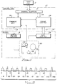
- a data processing system is controlled by at least one host central processing unit (CPU) 10 (FIG. 1) to store, retrieve and manipulate data.
- the data processing system includes at least one control unit 12 and at least one device, in this case a magnetic tape recording device 14.
- the control unit 12 accepts the commands and data from the CPU 10 via channel adaptors 16, and controls itself and the devices accordingly.
- the device may be a magnetic disk or optical recorder.
- the magnetic tape recording device 14 includes means for controlling the handling of media in the form of tape 22, a motion control 18 connected by a cable 19 to a command unit 30 in the control unit 12, a drive 20 for transporting the tape 22 past a magnetic head 24 for writing and reading data to and from the tape, and a data control 26 providing read and write circuits to operate the head 24 and connected by a cable 27 to a format control 28 in the control unit 12.
- the format control 28 is connected by a data cable 29 to the channel adapter 16.
- the command unit 30 takes commands transmitted to the channel adaptors 16 by the hosts 10 and controls the operation of the drive 20 via the motion control 18 and the flow of data to and from the channel adaptors 16 through the format control 28 and the data control 26.
- the command unit 30 includes a status store 40 (FIG. 2A), a microprocessor 42, a control store 44 and a device adapter 46.
- the format control 28 (FIG. 1) includes a buffer control 48 (FIG. 2A) which operates under control of the microprocessor 42 to store the data to be written on tape 22 by a write formatter 50 connected by cable 51 to a write circuit 52 (FIG. 2B) which, in turn, is connected to the head 24.
- the buffer control 48 (FIG. 2A) also controls the data flow on a read cycle to store the data processed by a read circuit 54 (FIG. 2B) from the head 24 and transmitted to a read detect circuit 56 (FIG. 2A) over a connecting cable 58.
- the read detect circuit 56 is connected to a read formatter 60 which in turn is connected to the buffer control 48.
- the drive 20 (FIG. 1) is under control of the motion control 18 to accomplish the controlled transporting of the tape 22 past the head 24 to accomplish the reading and writing of the magnetic transitions form and to the tape 22.
- the tape recording device 14 includes a supply reel motor 62 (FIG. 2B), a tachometer control 64, a carriage 66, and a carriage control 68, a take-up reel 70, a take-up reel motor 72, tachometer control 74, a threading mechanism 76, an idler wheel 80, compliant tape guides 82, and a tape tension control 84 along a tape path 78.
- the tape 22 is contained in a cartridge 86 placed into the carriage 66.
- the cartridge 86 includes a supply reel 88 and a leader block 90 for threading by the threading mechanism 76.
- tape system may be found in US-A-4,125,881, US-A-4,435,762, US-A-4,467,411, US-A-4,334,656, US-A-4,339,936, US-A-4,389,600, US-A-4,406,425, US-A-4,685,005, US-A-4,452,406, US-A-4,454,282, US-A-4,525,424, US-A-4,568,611.
- the head 24 may be an 18-track magnetic transducing head or a 36-track interleaved magnetic transducing head, depending upon the particular tape system. Each type of head writes a unique type of FID on the tape 22 to indicate the recording format (18-track or 36-track) of data written thereby.
- a first portion of the tape 22 does not contain any data or any signals which can be used to identify the tape 22 and its cartridge 34.
- This 'no data' section is the portion of the tape 22 that is wrapped over the takeup reel 70 to cushion the succeeding length of tape from any takeup reel irregularities.
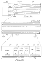
- IBM 3490E Tape Drive the data is placed onto eighteen odd and eighteen even tracks, the odd tracks being recorded at one time in the direction of arrows 100, and the even tracks being recorded in the opposite direction, that of the arrows 102.
- the recording starts at the physical beginning of tape (PBOT) with a format identifier mark (FID) (FIG. 3B).
- the remainder of the tape length to a logical beginning of tape is set by a tape volume label standards ANSI X327-1978 level 4 for the IBM 3480/3490 Tape Drives, as updated to include a volume identifier as the volume ID (VOLID) section.
- the FID mark is recorded at the beginning of the tape 22 after the PBOT when a write command is issued while the tape is positioned at either the beginning of the tape or the logical beginning of the tape.
- the control unit 12 repositions the tape so that the FID mark begins at the PBOT.
- the FID mark provides the subsystem with an indication of which format is being used to record the data on the tape. The subsystem uses the mark to determine if it is capable of reading the data or adding data to the end of the previously written data.
- the VOLID format (FIG. 3C) includes a volume serial number (VOLSER) section 104, an accessibility byte section 105, a label standards level section 106, an ASCII flag section 107, a cyclic redundancy checking (CRC) section 108 which is an error checking section, and a termination symbol section 109.
- the termination symbol of section 109 is a totally different symbol from any standard one or zero symbol.
- the termination symbol is a standard ERG followed by an IBG.
- the termination symbol is used as a "loss of synch" indication which is an error determination showing that whatever was read previously in the VOLID is incorrect.
- the VOLID region is written as the first record on the volume recorded on the tape.
- the volume identifier, the VOLSER is used by the host operating system to determine the disposition of the data recorded on the tape.
- the customer data in step 0 according to the afore-mentioned tape volume label standards contains a VOL1 section which is the first four bytes, bytes 0 to 3, encoded in either ASCII or EBCDIC. This section starts the recording of the identification of the data recorded on the tape.
- the VOLSER covers bytes 4 to 9 with each byte corresponding to a character in the VOLSER recorded in either ASCII or EBCDIC.
- the VOLID region is written it is not changed by the control unit unless block zero is rewritten for the entire cartridge.
- the VOLID region will be capable of being sensed by all tape drive devices using the cartridge of this design. If the cartridge mounted on the drive does not have a valid tape format ID in the FID region, it is considered to be a void tape.
- the VOLID region is recorded immediately following the FID mark and precedes the LBOT.
- the VOLID and especially the VOLSER is composed of a set of specially defined patterns of marks which encode the volume identification information.
- the 18-track format data written on the tape 22 may be read by a 36-track tape system.
- the problems arise when it is necessary to read the VOLID information from a 36-track tape system in an 18-track tape system.
- the tape cartridge 34 is designed to be inserted into either an 18-track tape system or a 36-track tape system. All tape systems must be able to distinguish between track density and tape recording formats to minimize attempts to access data on tapes incompatible therewith. It is necessary to be able to identify the volume serial (VOLSER) information from either density track system on either track system.
- VOLSER volume serial
- the difficulty arises when a 36-track tape with its very narrow tracks needs to have its VOLSER information sensed by the 18-track magnetic head.
- Reference is made to the aforementioned tape volume label standards for a more complete description of the accessibility byte and the label level standards section. The description of the present invention proceeds with the description of the advantages of the features now included in the VOLSER and the termination symbol sections.
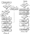
- the encoding of the VOLSER information for the host is a machine executed procedure which starts by checking in step 110 (FIG. 4) whether VOL1 is encoded in ASCII. If it is, the procedure continues along the Y line to step 112 which sets the ASCII flag equal to a one "1" symbol for the sixty fifth symbol 64 in section 107 (FIG. 3C). If not, the procedure continues along the N line to step 114 where the procedure checks whether VOL1 is instead encoded in EBCDIC. If VOL1 is not encoded in either ASCII or EBCDIC, the N line is taken to step 116 which shows that a VOLID region will not be written on this tape.
- step 118 If the VOL1 information is encoded in EBCDIC rather than ASCII, the ASCII flag symbol in section 107 is set to a zero "0" symbol in step 118.
- the procedure continues from step 112 or step 118 to write the VOLSER information in section 104 and information in sections 105 and 106 into a VOLID table in memory using the first sixty four symbols 0-63 in step 120. The pattern used is shown in FIG. 5.
- the encoding procedure continues in step 122 where the error checking symbols of the CRC system are built and occupy symbols 65 to 72 in section 108 (FIG. 3C).
- the data information to be placed on the tape is encoded next in step 124.
- the importance of this invention is shown in the format that the VOLSER information is recorded on the tape.
- the pattern is 1011001111 for the first ten symbols of the 48 symbol VOLSER.
- the VOLSER is a variable length identifier signal in that the symbols for "1" and "0" cover different numbers of units and thus the number of units covered by the 48 symbols varies with the mix of the ones and zeros.
- VOLID variable length symbol code group volume serial number VOLSER of the Volume ID
- a one being symbolically represented as a high level covering a first two units of a group, that is, a one is represented as two units of an erase gap signal ERG
- a zero is represented as a high level signal covering a first one unit of a group, that is, a zero is represented as one unit of an ERG.
- Successive symbols, whether a one or a zero, are separated by an Inter Block Gap (IBG) signal which is symbolically shown as a low level covering four units of the VOLSER group.
- IBG Inter Block Gap
- the even tracks are not used the VOLID region and are written with a high frequency signal that causes erasure of even tracks so that when the 18 track drive reads the 36 track drive, it senses the data on the odd tracks only.
- the odd tracks are used in encoding the VOLSER.
- the 18 odd tracks of the 36 tracks are divided in six groups of three tracks each when the VOLSER is recorded.
- the ERG and IBG symbols are represented by different active tones in the different groups. For instance, The IBG mark is an inactive tone in zones A, D and F and an active tone in zones B, C and E.
- the ERG mark is represented by an active tone for zones A, D and E.
- Zone A covers tracks 1, 13 and 25 for instance.
- Zone B covers tracks 3, 15 and 27.
- the other zones cover other tracks.
- the tracks covered by each zone does not form a part of this invention and thus will not be completely described herein.
- the information is given to show the implementation in an IBM 3490E Tape Drive.
- one symbol appears in one group of units.
- the first symbol is a "1" and therefore a first group G1 covers six units, two units of an ERG signal shown as a high level in FIG. 5 and four units of an IBG signal shown as a low level.
- the second group is a "0" and therefore a second group G2 covers five units, one unit of an ERG signal followed by four units of an IBG signal. All of the groups G1 to G10 cover a variable number of units depending upon the symbols of the VOLSER.
- the first embodiment of a decode procedure for decoding the VOLSER signal is shown in FIG. 6.
- the first step 140 in the decode procedure is to sample the second unit of the group for a first status determination.
- the first status determination is then obtained in step 141.
- the next step 142 is to sample the fourth unit after the first status determination.
- the second status determination is obtained.
- a decision step 146 determines whether the first status is equal to the second status determination. If the first and second status are both equal to an IBG, or both are equal to an ERG, or both are equal to an indeterminate status, i.e. cannot be sensed correctly, an error has occurred. If an error correction procedure is not included, step 150 follows which terminates the process. If an error correction procedure follows, decision step 148 is included to carry the process to FIG. 7A.
- the process continues in a decision step 152 where whether the first status is equal to ERG is determined. If it is not, the first status is either an IBG or is of indeterminate status, and a further decision step 156 follows, in which a determination is made whether the second status is equal to an IBG or not. If the second status is not an IBG, i.e. is either an ERG or of indeterminate status, then the symbol is determined or corrected to be a "0" in step 154. The process then continues to step 160 of the sampling of the next group.
- step 158 follows where the symbol is determined to be a "1". If the second status is an IBG, and the first status was of indeterminate status, i.e., not an ERG, then step 158 also follows and the symbol must be a "1".
- step 160 the next group unit is sampled. The next group starts after the ending of the IBG signal which, after a symbol equal to a "1" determination, is at the seventh unit. Two units are added and the first status determination is made for the next group in step 161. The process continues to a decision step 162 where the presence of the last group is determined.
- step 164 If this is the last symbol to be determined and there is no error correction procedure, the decode will end the procedure in step 164. If an error correction procedure is included, decision step 163 will be included in the process to carry the process out to FIG. 7B. If it is not the last symbol to be determined, the flow continues from the decision step 162 to the step 142 for the second status determination of the next group.
- step 160 follows. In step 160, after a "0" symbol is sensed, the next group of units will start at the sixth unit so one unit must be added and the first status determination made for the next group in step 161. The process then continues in the decision step 162 for either the return to the step 142 if more symbols are to be sensed or to the step 164 to end the decode procedure unless the error correction procedure of FIG. 7B is included as determined in the decision step 163.
- the first status determination of steps 140 and 141 will find an ERG status at unit 2 of the first group G1.
- the sixth unit status is an IBG status, a low level shown at unit six in FIG. 5.
- the first status is not equal to the second status, so no error is detected in the decision step 146 and the no line is taken to decision step 152.
- the first status is an ERG signal so the yes line is taken to the step 158.
- the step 158 shows that the symbol sensed is a one "1" symbol. The process continues to the step 160 where the next group G2 is to be determined.
- the first status determination of an IBG is made on the eighth unit (FIG. 5) in the step 161. This is not the last group, so the no line is taken to the step 142.
- the fourth unit after the eighth unit, the twelfth unit, is sensed in step 142 and the second status determination is an ERG signal (FIG. 5) for the step 144.
- the first status is not an ERG signal so the no line is taken from the decision step 152 to the decision step 156 where whether the second status determination is equal to IBG is questioned.
- the second status has been determined to be an ERG so the no line is taken from the decision step 156 to the step 154 which shows that a '0' symbol has been determined to be the symbol of the second group G2.
- step 160 the next group G3 is sampled by sampling the first status determination of the plus one unit or the thirteenth unit of FIG. 5.
- the thirteenth unit, the second unit of group G3 is an ERG status, see FIG. 5. Again this is not the last group and the procedure continues from the decision step 162 to the step 142 to sample the fourth unit of group G3 after the second unit of Group G3, which is the seventeenth unit.
- the seventeenth unit has an IBG status.
- the procedure continues until the last group G48 is sampled and the decision step 162 yes line is taken to the step 164, ie, no correction procedure of FIGS. 7A and 7B is present, to end the decode process.
- any other number of groups could be included for the VOLSER representation shown in FIG. 5.
- a lesser number of groups would occur for a lesser number of symbols in the VOLSER.
- More units could be added to create more groups and thereby increase the number of symbols in the VOLSER.
- the number shown in FIG. 5 should not be taken as a limitation of the VOLSER symbols.
- the decode embodiment of FIG. 6 includes some error correction as is discussed.
- the addition of the procedures of FIGS. 7A and 7B corrects the errors when the first and second status determinations of one group are equal.
- the addition of the error correction is shown in the decision steps 148 and 163 of FIG. 6. If the procedures of FIGS. 7A and 7B is included, the yes line will be taken from the decision step 148 to a first step 169 (FIG. 7A) in which the group number under consideration for the correction of an error is stored.
- the process then continues to step 170 which states that the unit of the second status determination plus one should be sampled in a step 172 where a third status determination is made.
- the second status determination of the first group G1 is at unit six.
- the third status determination for group G1 is at unit seven.
- the third status determination unit plus one is then sensed in a step 174 and a fourth status determination of unit eight is done as called for in a step 176. If either of the third and fourth status determinations is indeterminate (?), as queried in a decision step 177, the procedure terminates in step 175. The error cannot be corrected. If neither of the third and fourth status determinations is indeterminate, the procedure continues to a decision step 178 where it is determined whether the third status is an ERG. If the third status determination is not an ERG, the procedure continues in a step 180 where it is determined if the fourth status is an IBG. Then, if the fourth status is not an IBG, the procedure continues to a step 182 which shows that this status sequence cannot be corrected and continues to a step 184 where the process is terminated because the error cannot be corrected by this sequence.
- the procedure goes to a step 186 where the stored group symbol is determined to be a '0' symbol.
- the third status being the status of the second group which is the group following the error group, the status of the second symbol is already determined also to be a '0' symbol in step 188.
- the procedure returns to the step 160 (FIG. 6) where the next, or third, group status is sampled by going to the group following the stored group plus one unit for the first status determination of the third group in step 161.
- the procedure of FIG. 6 can be continued for the remaining symbols of the VOLSER.
- the procedure continues to a decision step 190 where the fourth status is questioned. If the fourth status is not an ERG after the third status was determined to be an ERG, the procedure leads to a step 187 where the stored group symbol is assumed to be a zero "0", and the stored group plus one symbol is assumed to be a one "1" in step 189.
- the symbols are set to the determination, because the parity status will be checked later and if the assumption is incorrect, the symbols will be reversed as the parity will show that the assumption was incorrect and the opposite is in fact correct. This parity check is shown in FIG. 7B.
- the group number of the stored group and the stored group plus one will be the groups that have their symbols reversed.
- a one is added to the error signal in step 192.
- the procedure continues to a decision step 194 which determines whether more than one such error has been corrected. If so, the procedure goes to a step 196 where too many errors have occurred, i.e., more than one, and the procedure is terminated in step 198. If more than one error is sensed in the decode procedure, the reading of the VOLSER cannot be determined to be reliable and any further decoding may lead to an incorrect VOLSER. If not more than one error is sensed in step 194, the procedure goes back to step 160 (FIG. 6).
- the procedure goes to a step 200 and a step 202 where the first and third status determination are found to be ERGs and thus the symbols of the first stored group and the group following the stored group are both a "1".
- the procedure then continues back to the step 160 (FIG. 6).
- the step 160 provides for the sampling of the next group of units and the step 161 determines the first status determination of the second unit of the next group.
- the decision step 162 determines whether the last group is having its status determined and ends the procedure if it is, or returns the procedure to the step 142 to sample the status of the next group of units.
- the last group G48 (FIG. 5), cannot be corrected using the flow procedure of FIGS. 7A and 7B as there is no "group following the stored group" to assist in the correction process as is necessary in that flow procedure. This can be solved by adding another group of units, not for its symbol, but to assist only in the correction procedure.
- the decision step 162 determines that this is the last group and the procedure goes to the decision step 163. If the error correction procedure (FIGS. 7A and 7B) is included in the subsystem, the procedure continues to decision step 220 (FIG. 7B) where the procedure checks whether an error symbol was checked using the error correction procedure of FIG. 7A. If there is no error symbol, ie, the error symbol is zero, the procedure goes to a step 222 to end the procedure. If there has been one and only one error corrected, the procedure goes to a step 224 to compute a parity P1 from the received, that is, just read, groups of units. The symbols of the odd groups are used to compute the received parity P1.
- a step 226 then checks the parity that accompanied the received groups, a received parity P2, the parity in symbol 64.
- the procedure continues to a decision step 228 where P1 is checked for its status relative to P2. If P1 is equal to P2, then the symbols found in the correction procedure for the stored group and the stored group plus one are correct, the stored group symbol is equal to "0" and the stored group plus one, the group following the stored group, symbol is equal to "1". The procedure goes on to end in step 222.
- the procedure goes to a step 232 where the stored group symbol is reversed and set equal to a "1" and then to a step 234 where the stored group plus one symbol is also reversed and set equal to a "0".
- the procedure then ends in step 222.
- the symbols are reversed because the procedure of FIG. 7A made an incorrect assumption and the status of the parity read as compared to the status of the parity accompanying the symbols should be that the opposite symbols are the correct symbols because the opposite symbols would make the parity of both P1 and P2 the same.
- a decoding table of the nine possibilities that arise from the decoding procedure of FIGS. 6, 7A and 7B will now be discussed.
- the output symbols as a result of the sampling of units two and six of the first group G1 are equally applicable to the second and sixth units of any succeeding group (FIG. 5). If the status of the first status determination of the procedure of FIG. 6 is determined to be an ERG status, then whether the status of the second status determination of FIG. 6 is an IBG status or an indeterminate status, i.e., cannot be read, then the output symbol is a "1". If the status of the first status determination is indeterminate but the status of the second determination is an IBG, then the output symbol is also a "1".
- the output symbol is a "0"
- whether the second status is determined to be an ERG status or an indeterminate status If the first status determination is indeterminate but the second status determination is found to be an ERG status, then the output symbol is a "0".
- the third and fourth status determinations of succeeding units of the next group can provide outputs of all but one status reading by sampling the status of the following group. The output of the decoding procedure of FIGS.
- the 7A and 7B uses the status determinations of the group following the group where the error is detected to correct the error and also determine the status of the following group.
- the group number of the group that has the error is stored. If the third and fourth status determinations are both ERG status, then the output symbol of the stored group is a "1" as is also the output of the group following the stored group. If the third and fourth status determinations are both an IBG status, then both the stored group and the group following the stored group have output symbols equal to "0". If the third status determination is an ERG status and the fourth status is an IBG, then the output symbol is first assumed to be a "0" for the stored group and the group after the stored group is assumed to be a "0". The final symbol of the stored group and its group following the stored group is determined by the status of the parity symbol which is the required extra symbol for the error correction procedure of FIG. 7B.
- the parity system reads all the ERG status of the odd groups of the VOLSER.
- the parity system adds a one if the count is odd and a zero if the count is even. If the computed parity count P1 is the same as the received parity P2, the symbol output of the first stored group is a "0" and the symbol of the group following the stored group is a "1".
- the symbol outputs are reversed if the parity found in the count as read in the decoding is not the same as that stored from the encoding of the VOLSER and stored in the symbol 64. If the third status determination is an IBG and the fourth status determination is an ERG, then the output is not correctable and decoding must be terminated.
- a serial number generally includes a fixed number of symbols and the subsystem can count the number of symbols read and compare with the number of symbols of the recorded serial number.
- the present invention provides a format that produces a reliable serial number decoding together with error detection and correction.
- the last group with the encoded symbol is not correctable, refer to the symbolic encoding of a VOLSER as is shown in FIG. 5. If an error occurs in the last group, there is no further group to be used in the correction procedure of FIGS. 7A and 7B. If an error occurs, for instance, in group G48 of FIG. 5, there is no "group G49" to assist in the correction of the error in group G48. To solve this, a boundary group (group G49) can be added of a known symbol, either a one or a zero. Then the error correction procedure of FIGS. 7A and 7B can be entered to correct the group G48 error. In this instance, the error correction can occur over the entire data stream. The symbol of the last group G48, for instance, could be repeated in the boundary group G49.
- the invention has been described for use in a magnetic tape system, but could be embodied in any applicable peripheral storage system employing removable, multitrack, sequentially recorded storage media. Also, different types of FIDs, VOLSERs, transducers, recording formats, means for determining the characteristics of the storage media, etc. may be used.
Landscapes
- Engineering & Computer Science (AREA)
- Signal Processing (AREA)
- General Engineering & Computer Science (AREA)
- Signal Processing For Digital Recording And Reproducing (AREA)
- Digital Magnetic Recording (AREA)
Claims (18)
- Un procédé de codage d'un sous-jeu critique de données stockées sur un milieu, caractérisé en que le sous-jeu critique de données comprend une pluralité d'unités ayant un premier état logique, représenté sous forme de premier signal spécial (ERG) couvrant les deux premières unités d'un groupe (G) de six unités, et un deuxième état logique, représenté comme étant le premier signal spécial (ERG) couvrant la première unité d'un groupe (G) de cinq unités, les deux étant suivis par un deuxième signal spécial (IBG) couvrant quatre unités.
- Un procédé selon la revendication dans lequel le sous-jeu critique est un signal d'identification (VOLSER).
- Un procédé selon la revendication 1 ou la revendication 2, dans lequel le premier état logique est celui valant "1", et le deuxième état logique est celui valant "0".
- Un procédé selon l'une quelconque des revendications précédentes, dans lequel le sous-jeu critique de données comprend une pluralité de groupes successifs, soit de six soit de cinq unités.
- Un procédé selon la revendication 4, dans lequel chaque groupe identifie un symbole.
- Un procédé de décodage d'un symbole pour un groupe codé par le procédé selon l'une quelconque des revendications précédentes, comprenant les étapes consistant à échantillonner un premier état de la deuxième unité du groupe, échantillonner un deuxième état d'une unité de quatre unités suivant la deuxième unité du groupe, et décoder un symbole du groupe, par utilisation du premier état et du deuxième état.
- Un procédé selon la revendication 6 comprenant l'étape de préparation pour l'échantillonnage d'un symbole, à partir d'un groupe successif en procédant à l'addition de deux unités à l'unité échantillonnée pour le deuxième état du groupe précédent, si le symbole ayant été échantillonné dans le groupe précédent est le premier état logique, ou l'addition d'une unité à l'unité ayant été échantillonnée pour le deuxième état du groupe précédent, si le symbole ayant été échantillonné dans le groupe précédent est le deuxième état logique.
- Un procédé selon la revendication 6 ou 7, comprenant, après l'étape d'échantillonnage visant à obtenir le deuxième état, l'étape de détermination du fait qu'une erreur s'est produite par le fait que le premier état est égal au deuxième état et, dans l'affirmative, l'achèvement du processus.
- Un procédé selon la revendication 6 ou 7, comprenant après l'étape d'échantillonnage visant à obtenir le deuxième état, l'étape de détermination dictant si le premier état est égal au deuxième état, et, dans l'affirmative, la mémorisation d'un numéro de groupe correspondant au groupe dans lequel le premier état est égal au deuxième état, et l'échantillonnage de l'état des premières et deuxièmes unités du groupe subséquent, pour déterminer les symboles du groupe mémorisé et du groupe faisant suite au groupe mémorisé.
- Un procédé suivant la revendication 9, dans lequel, si le troisième et le quatrième état ayant été échantillonné avec le deuxième signal spécial, le processus est achevé et les symboles du groupe mémorisé et du groupe subséquent au groupe mémorisé ne sont pas déterminés.
- Un procédé selon la revendication 9 ou 10, dans lequel le symbole de groupe mémorisé est supposé avoir un deuxième état logique, et le groupe qui suit le groupe mémorisé est supposé avoir un premier état logique, si le troisième état est déterminé comme comprenant le premier signal spécial et que le quatrième état est déterminé comme comprenant le deuxième signal spécial.
- Un procédé selon l'une quelconque des revendications 6 à 11, comprenant l'étape de codage d'un symbole de parité avec le codage du sous-jeu critique des données, l'échantillonnage de parité des symboles des groupes impairs du sous-jeu critique.
- Un procédé selon la revendication 12, comprenant les étapes de détermination dictant si le premier état a été déterminé comme étant égal au deuxième état dans une étape précédente, le calcul d'une parité à partir des symboles des groupes impairs, et la détermination du fait que la parité calculée est égale à la parité codée, et l'achèvement du processus si la parité calculée est égale à la parité codée, et, sinon, fixation du symbole de groupe mémorisé à une valeur égale à un premier état logique, les fixations du symbole du groupe suivant le deuxième groupe à une valeur égale à un deuxième état logique.
- Un système de stockage périphérique destiné à lire des données sur un milieu de stockage de données (22) amovible y étant monté, le milieu de stockage de données ayant un sous-jeu critique de données stocké sur le milieu, en un emplacement parmi une pluralité d'emplacements sur celui-ci, caractérisé en ce que le sous-jeu critique de données (VOLSER) comprend une pluralité d'unités dans un groupe (G), chaque groupe identifiant un symbole et un premier état logique étant représenté sous forme de premier signal spécial (ERG) couvrant les deux premières unités d'un groupe de six unités, et un deuxième état logique étant représenté comme étant le premier signal spécial (ERG) couvrant la première unité d'un groupe de cinq unités, les deux étant suivis par un deuxième signal spécial (IBG) couvrant quatre unités du groupe.
- Un système selon la revendication 14, dans lequel le premier état logique est celui valant "1", le deuxième état logique est celui valant "0".
- Un système selon la revendication 14 ou la revendication 15, dans lequel le sous-jeu critique de données est un signal d'identification.
- Un système selon la revendication 14, 15 ou 16, dans lequel le sous-jeu critique de données comprend une pluralité de groupes ayant chacun un symbole.
- Un système selon l'une quelconque des revendications 14 à 17, dans lequel les données sont lues par un procédé d'accès séquentiel.
Applications Claiming Priority (2)
| Application Number | Priority Date | Filing Date | Title |
|---|---|---|---|
| US78483991A | 1991-10-30 | 1991-10-30 | |
| US784839 | 1991-10-30 |
Publications (3)
| Publication Number | Publication Date |
|---|---|
| EP0540316A2 EP0540316A2 (fr) | 1993-05-05 |
| EP0540316A3 EP0540316A3 (fr) | 1995-01-18 |
| EP0540316B1 true EP0540316B1 (fr) | 1997-09-24 |
Family
ID=25133688
Family Applications (1)
| Application Number | Title | Priority Date | Filing Date |
|---|---|---|---|
| EP92309882A Expired - Lifetime EP0540316B1 (fr) | 1991-10-30 | 1992-10-28 | Procédé de codage |
Country Status (4)
| Country | Link |
|---|---|
| US (1) | US5420727A (fr) |
| EP (1) | EP0540316B1 (fr) |
| JP (1) | JP2755370B2 (fr) |
| DE (1) | DE69222391T2 (fr) |
Families Citing this family (9)
| Publication number | Priority date | Publication date | Assignee | Title |
|---|---|---|---|---|
| US5517670A (en) * | 1992-12-30 | 1996-05-14 | International Business Machines Corporation | Adaptive data transfer channel employing extended data block capability |
| US5828507A (en) * | 1994-07-27 | 1998-10-27 | Sony Corporation | Method for recording data onto tape-shaped recording media for high-speed retrieval based on system log information recorded in a leading partition |
| US5572378A (en) * | 1994-06-13 | 1996-11-05 | Imation Corp. | Direct file access system for magnetic tape |
| WO1997027703A1 (fr) * | 1996-01-26 | 1997-07-31 | Exabyte Corporation | Procede et dispositif polyvalent d'enregistrement numerique et support correspondant |
| US6038613A (en) * | 1997-11-14 | 2000-03-14 | International Business Machines Corporation | Prefetching and storing device work information from multiple data storage devices |
| JP4324993B2 (ja) * | 1998-02-17 | 2009-09-02 | ソニー株式会社 | データ転送方法および装置 |
| US7126779B2 (en) * | 2001-12-04 | 2006-10-24 | Quantum Corporation | Tape media identification code |
| US7760104B2 (en) * | 2005-04-08 | 2010-07-20 | Entegris, Inc. | Identification tag for fluid containment drum |
| US8001340B2 (en) * | 2007-04-19 | 2011-08-16 | International Business Machines Corporation | Method for determining allocation of tape drive resources for a secure data erase process |
Family Cites Families (10)
| Publication number | Priority date | Publication date | Assignee | Title |
|---|---|---|---|---|
| JPS566030A (en) * | 1979-06-28 | 1981-01-22 | Hino Motors Ltd | System for controlling injection timing at starting engine |
| US5084852A (en) * | 1980-07-16 | 1992-01-28 | Discovision Associates | System for recording digital information in a pulse-length modulation format |
| CA1161946A (fr) * | 1980-07-26 | 1984-02-07 | Sony Corporation | Methode et appareil d'enregistrement de donnees numeriques sur un support |
| JP2534643B2 (ja) * | 1983-06-28 | 1996-09-18 | 株式会社東芝 | フロツピ−デイスク制御システム |
| US4685005A (en) * | 1983-07-18 | 1987-08-04 | International Business Machines Corporation | Two-module-read, read-after-write, bi-directional tape drive |
| US4802154A (en) * | 1983-10-13 | 1989-01-31 | Laser Magnetic Storage International Company | High density codes for optical recording |
| JPS60140571A (ja) * | 1983-12-28 | 1985-07-25 | Toshiba Mach Co Ltd | 磁気テープのデータ記録設定方法 |
| JPS60140570A (ja) * | 1983-12-28 | 1985-07-25 | Sony Corp | Pcm信号の記録再生装置 |
| JP2647649B2 (ja) * | 1986-07-03 | 1997-08-27 | パイオニア株式会社 | 光ディスク記録方法 |
| JPH01256071A (ja) * | 1988-04-04 | 1989-10-12 | Pioneer Electron Corp | 記録媒体及び記録再生方式 |
-
1992
- 1992-09-24 JP JP4254869A patent/JP2755370B2/ja not_active Expired - Fee Related
- 1992-10-28 EP EP92309882A patent/EP0540316B1/fr not_active Expired - Lifetime
- 1992-10-28 DE DE69222391T patent/DE69222391T2/de not_active Expired - Fee Related
-
1994
- 1994-01-24 US US08/186,363 patent/US5420727A/en not_active Expired - Fee Related
Also Published As
| Publication number | Publication date |
|---|---|
| DE69222391T2 (de) | 1998-03-26 |
| DE69222391D1 (de) | 1997-10-30 |
| EP0540316A2 (fr) | 1993-05-05 |
| JP2755370B2 (ja) | 1998-05-20 |
| JPH05234258A (ja) | 1993-09-10 |
| EP0540316A3 (fr) | 1995-01-18 |
| US5420727A (en) | 1995-05-30 |
Similar Documents
| Publication | Publication Date | Title |
|---|---|---|
| US5369532A (en) | Method and apparatus for managing data on rewritable media to define read/write operational status | |
| KR920002800B1 (ko) | 기록 테이프상에 데이타를 저장하는 방법 | |
| EP0535920A2 (fr) | Traitement de données | |
| US5245485A (en) | Multiple tape thickness, multiple recording format tape drive systems | |
| EP0540316B1 (fr) | Procédé de codage | |
| JPH08501172A (ja) | データ記録システム用ボリウムフォーマットテーブル | |
| JP3652372B2 (ja) | データ及び補助情報を記憶するための方法及び装置 | |
| US5268802A (en) | Reading non-standard tapes on tape drives | |
| JP4398589B2 (ja) | データ記憶装置およびその方法 | |
| JPH08501169A (ja) | ディジタルサーボトラックフォーマット | |
| JPH08500927A (ja) | 改良された長手方向及びらせんサーチ機能を有するデータ記録システム | |
| EP0597707A2 (fr) | Appareil d'enregistrement/reproduction sur bande magnétique | |
| US5475542A (en) | Method and apparatus for improving inter-block gap length tolerance and locate accuracy for write appends | |
| EP0939956A1 (fr) | Bandes magnetiques pour enregistrement et lecture a haute densite | |
| US5485476A (en) | Method and system for error tolerant synchronization character detection in a data storage system | |
| JPH08501175A (ja) | 改良された予約機能を有するデータ記録システム | |
| KR920002799B1 (ko) | 데이타 저장 방법 | |
| JPH08501173A (ja) | データ記録システム用長手方向トラックフォーマット | |
| JPH09231508A (ja) | デマーキング機能を有するデータ記録システム及び方法 | |
| JP3446852B2 (ja) | 記録媒体の動き制御方法および装置 | |
| JPH08501171A (ja) | 単一非記録検出を有するデータ記録システム | |
| JPH08501176A (ja) | 論理上書き機能を有するデータ記録システム | |
| JPH08501174A (ja) | 改良された自動書き替え機能を有するデータ記録システム及び書き替え方法 | |
| US6057973A (en) | Method of seeking to tape segment without the use of inter-segment gap | |
| JP2679165B2 (ja) | ディジタルテープレコーダ |
Legal Events
| Date | Code | Title | Description |
|---|---|---|---|
| PUAI | Public reference made under article 153(3) epc to a published international application that has entered the european phase |
Free format text: ORIGINAL CODE: 0009012 |
|
| AK | Designated contracting states |
Kind code of ref document: A2 Designated state(s): DE FR GB |
|
| 17P | Request for examination filed |
Effective date: 19930819 |
|
| PUAL | Search report despatched |
Free format text: ORIGINAL CODE: 0009013 |
|
| AK | Designated contracting states |
Kind code of ref document: A3 Designated state(s): DE FR GB |
|
| GRAG | Despatch of communication of intention to grant |
Free format text: ORIGINAL CODE: EPIDOS AGRA |
|
| 17Q | First examination report despatched |
Effective date: 19970130 |
|
| GRAH | Despatch of communication of intention to grant a patent |
Free format text: ORIGINAL CODE: EPIDOS IGRA |
|
| GRAH | Despatch of communication of intention to grant a patent |
Free format text: ORIGINAL CODE: EPIDOS IGRA |
|
| GRAA | (expected) grant |
Free format text: ORIGINAL CODE: 0009210 |
|
| AK | Designated contracting states |
Kind code of ref document: B1 Designated state(s): DE FR GB |
|
| REF | Corresponds to: |
Ref document number: 69222391 Country of ref document: DE Date of ref document: 19971030 |
|
| ET | Fr: translation filed | ||
| PLBE | No opposition filed within time limit |
Free format text: ORIGINAL CODE: 0009261 |
|
| STAA | Information on the status of an ep patent application or granted ep patent |
Free format text: STATUS: NO OPPOSITION FILED WITHIN TIME LIMIT |
|
| 26N | No opposition filed | ||
| PGFP | Annual fee paid to national office [announced via postgrant information from national office to epo] |
Ref country code: FR Payment date: 19991018 Year of fee payment: 8 |
|
| PG25 | Lapsed in a contracting state [announced via postgrant information from national office to epo] |
Ref country code: FR Free format text: LAPSE BECAUSE OF NON-PAYMENT OF DUE FEES Effective date: 20010629 |
|
| REG | Reference to a national code |
Ref country code: FR Ref legal event code: ST |
|
| REG | Reference to a national code |
Ref country code: GB Ref legal event code: IF02 |
|
| PGFP | Annual fee paid to national office [announced via postgrant information from national office to epo] |
Ref country code: GB Payment date: 20061002 Year of fee payment: 15 |
|
| PGFP | Annual fee paid to national office [announced via postgrant information from national office to epo] |
Ref country code: DE Payment date: 20061016 Year of fee payment: 15 |
|
| GBPC | Gb: european patent ceased through non-payment of renewal fee |
Effective date: 20071028 |
|
| PG25 | Lapsed in a contracting state [announced via postgrant information from national office to epo] |
Ref country code: DE Free format text: LAPSE BECAUSE OF NON-PAYMENT OF DUE FEES Effective date: 20080501 |
|
| PG25 | Lapsed in a contracting state [announced via postgrant information from national office to epo] |
Ref country code: GB Free format text: LAPSE BECAUSE OF NON-PAYMENT OF DUE FEES Effective date: 20071028 |