EP0539971B1 - Méthode et appareil pour délivrer des cordons multiples d'un liquide visqueux - Google Patents
Méthode et appareil pour délivrer des cordons multiples d'un liquide visqueux Download PDFInfo
- Publication number
- EP0539971B1 EP0539971B1 EP92118486A EP92118486A EP0539971B1 EP 0539971 B1 EP0539971 B1 EP 0539971B1 EP 92118486 A EP92118486 A EP 92118486A EP 92118486 A EP92118486 A EP 92118486A EP 0539971 B1 EP0539971 B1 EP 0539971B1
- Authority
- EP
- European Patent Office
- Prior art keywords
- nozzle
- discharge
- nozzle body
- adhesive
- distribution channel
- Prior art date
- Legal status (The legal status is an assumption and is not a legal conclusion. Google has not performed a legal analysis and makes no representation as to the accuracy of the status listed.)
- Expired - Lifetime
Links
- 239000011324 bead Substances 0.000 title claims description 26
- 239000007788 liquid Substances 0.000 title description 6
- 239000000463 material Substances 0.000 claims description 15
- 238000012546 transfer Methods 0.000 claims description 10
- 230000005484 gravity Effects 0.000 claims description 6
- 239000012815 thermoplastic material Substances 0.000 claims description 2
- 239000012530 fluid Substances 0.000 claims 3
- 230000000717 retained effect Effects 0.000 claims 1
- 239000000853 adhesive Substances 0.000 description 107
- 230000001070 adhesive effect Effects 0.000 description 107
- 239000000758 substrate Substances 0.000 description 11
- 238000011144 upstream manufacturing Methods 0.000 description 8
- 230000000712 assembly Effects 0.000 description 5
- 238000000429 assembly Methods 0.000 description 5
- 239000012943 hotmelt Substances 0.000 description 5
- 229920001169 thermoplastic Polymers 0.000 description 5
- 239000004416 thermosoftening plastic Substances 0.000 description 5
- 206010013642 Drooling Diseases 0.000 description 4
- 239000004831 Hot glue Substances 0.000 description 4
- 208000008630 Sialorrhea Diseases 0.000 description 4
- 230000015572 biosynthetic process Effects 0.000 description 3
- 238000010438 heat treatment Methods 0.000 description 3
- 230000009467 reduction Effects 0.000 description 3
- 230000004044 response Effects 0.000 description 2
- 238000010008 shearing Methods 0.000 description 2
- 229920002472 Starch Polymers 0.000 description 1
- 238000013459 approach Methods 0.000 description 1
- 230000008859 change Effects 0.000 description 1
- 238000010276 construction Methods 0.000 description 1
- 238000013461 design Methods 0.000 description 1
- 230000008030 elimination Effects 0.000 description 1
- 238000003379 elimination reaction Methods 0.000 description 1
- 238000002474 experimental method Methods 0.000 description 1
- 230000007246 mechanism Effects 0.000 description 1
- 230000004048 modification Effects 0.000 description 1
- 238000012986 modification Methods 0.000 description 1
- 239000002245 particle Substances 0.000 description 1
- 239000008107 starch Substances 0.000 description 1
- 235000019698 starch Nutrition 0.000 description 1
- 239000000126 substance Substances 0.000 description 1
Images


Classifications
-
- B—PERFORMING OPERATIONS; TRANSPORTING
- B05—SPRAYING OR ATOMISING IN GENERAL; APPLYING FLUENT MATERIALS TO SURFACES, IN GENERAL
- B05C—APPARATUS FOR APPLYING FLUENT MATERIALS TO SURFACES, IN GENERAL
- B05C5/00—Apparatus in which liquid or other fluent material is projected, poured or allowed to flow on to the surface of the work
- B05C5/02—Apparatus in which liquid or other fluent material is projected, poured or allowed to flow on to the surface of the work the liquid or other fluent material being discharged through an outlet orifice by pressure, e.g. from an outlet device in contact or almost in contact, with the work
- B05C5/027—Coating heads with several outlets, e.g. aligned transversally to the moving direction of a web to be coated
- B05C5/0275—Coating heads with several outlets, e.g. aligned transversally to the moving direction of a web to be coated flow controlled, e.g. by a valve
Definitions
- This invention relates to an apparatus for dispensing multiple beads of viscous liquid, and, more particularly, to an apparatus for dispensing multiple beads of hot melt thermoplastic adhesive onto a substrate from closely spaced nozzle tips which do not contact the substrate wherein the beads can be dispensed intermittently without "cut off drool", i.e., the escape of adhesive in string or strand form from the discharge outlet of the nozzle tips when the flow of adhesive is intermittently interrupted.
- Patent No. 4,687,137 to Boger et al discloses an apparatus for dispensing beads of thermoplastic adhesive onto the non-woven layer of disposable diapers using a "coat hanger" die nozzle comprising a pair of die halves which together form channels for transmitting separate streams of adhesive to discharge outlets from which the adhesive is extruded as beads onto a substrate.
- coat hanger die nozzles are relatively expensive to produce and can clog or plug if the adhesive becomes contaminated with particles or the like. In the event of a clog, it is time-consuming to disassemble and clean such coat hanger dies.
- viscous liquid such as hot melt thermoplastic adhesive
- the device includes, in one preferred embodiment, a nozzle assembly having a nozzle body connected to a nozzle plate carrying a number of closely spaced nozzle tips which do not contact the substrate.
- the nozzle body is formed with an internal adhesive flow passage terminating with an elongated distribution channel having an outlet.
- a number of comparatively small diameter discharge passageways are formed in the nozzle plate, each connected to one nozzle tip, and means are provided for transferring the adhesive from the elongated distribution channel in the nozzle body into each of these discharge passageways, against the influence of gravity, for discharge from the nozzle tips as individual extruded beads.
- the nozzle plate is eliminated and the nozzle body is formed with both the internal flow passage and discharge passages.
- a number of connector bores interconnect the distribution channel or bore of the internal flow passage with the discharge passages to transfer adhesive therebetween.
- this invention is predicated upon the concept of providing a flow path from the valve mechanism of the dispensing device to the discharge outlet of a number of closely spaced nozzle tips wherein the flow of adhesive can be intermittently interrupted without creating leakage or cut off drool of adhesive from the nozzle tips.
- This is accomplished by locating the outlet of the distribution bore or channel vertically below the inlet of each of the discharge passageways, and by forming at least the inlet portion of the discharge passageways with a smaller cross sectional area than that of the distribution bore or channel.
- the vertical distance between the outlet of the distribution bore or channel and the inlet of each discharge passageway substantially prevents adhesive upstream from the nozzle tips from flowing into and through the nozzle tips to create cut off drool.
- the reduced cross sectional area of the inlet portion of each discharge passageway creates a back pressure in an upstream direction relative to the nozzle tips which substantially prevents leakage of the adhesive remaining within the nozzle tips when the dispenser is operated intermittently.
- the distribution channel in the nozzle body extends longitudinally along substantially its entire length, and inwardly from a first surface thereof.
- the nozzle plate is formed with an inner face which abuts the first surface of the nozzle body.
- Each of the discharge passageways is substantially L-shaped including a horizontally oriented inlet portion extending inwardly from the inner face of the nozzle plate, and a vertically oriented outlet portion which is connected to one of the nozzle tips.
- the means for transferring adhesive between the distribution channel and discharge passageways comprises a shim interposed between the abutting surfaces of the nozzle body and nozzle plate.
- the shim is formed with a number of longitudinally spaced, vertically oriented oval-shaped slots each having a lower end communicating with the distribution channel of the nozzle body, and an upper end connected to the inlet portion of one of the discharge passageways in the nozzle plate.
- the shim is formed with an elongated, longitudinally extending slot instead of a number of upright, oval slots. The lower portion of this elongated slot communicates with the distribution channel in the nozzle body, and the upper portion thereof is connected to the inlet portion of each discharge passageway in the nozzle plate.
- the individual oval slots and the elongated slot provide a flow path for the adhesive between the distribution channel and the discharge passageways.
- an elongated slot is formed in the nozzle plate which extends inwardly from its inner face and longitudinally along substantially the entire length thereof.
- the elongated distribution channel in the nozzle body communicates with the lower portion of the elongated slot in the nozzle plate, and the upper end of the elongated slot is connected to the inlet portion of each discharge passageway in the nozzle plate thus forming a vertically upwardly extending flow path for the adhesive between the nozzle body and the nozzle plate.
- an alternative embodiment of the nozzle assembly of this invention includes a nozzle body which is formed with both an internal flow passage and discharge passageways, with the nozzle plate of the above-described embodiment being eliminated.
- the internal flow passage includes an elongated distribution bore which is located vertically beneath the inlet portion of each discharge passageway.
- the discharge passageways are longitudinally spaced along the distribution bore and connector bores, which are angled vertically upwardly, interconnect the distribution bore with the inlet portion of each discharge passageway.
- each discharge passageway is preferably formed with a cross sectional area which is less than the cross sectional area of the distribution bore or channel. Because of this decrease in size of the flow path for the adhesive, the velocity of the adhesive is increased in the course of passage to and through the discharge passageways, at constant flow rate and pressure, so that it flows through the discharge passageways and nozzle tips at a faster rate than through the distribution bore or channel.
- the increased velocity of the adhesive within the discharge passageways and nozzle tips contributes to an increased "machineability" or shear capability such that the adhesive stream flowing therethrough can be more quickly and cleanly sheared in response to the termination of adhesive flow.
- the adhesive within the discharge passageways and nozzle tips is sheared at a point further upstream than had been possible in prior devices, thus reducing the volume of adhesive within the nozzle tips which can leak outwardly therefrom when the flow of adhesive is terminated.
- the comparatively smaller diameter discharge passageways create a back pressure which tends to draw or pull any adhesive remaining within the nozzle tips in an upstream direction to prevent leakage from the discharge outlets thereof.
- This back pressure also assists in creating a uniform volume of adhesive along the entire length of the longitudinally extending distribution bore or channel, so that the volume or quantity of adhesive supplied to each of the discharge passageways is substantially identical.
- adhesive beads are emitted from each of the nozzle tips which have substantially the same quantity of adhesive and the same bead size.
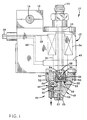
- an adhesive dispenser 10 is illustrated of the type disclosed in U.S. Patent No. 5,027,976 to Scholl et al, owned by the assignee of this invention.
- the structural details of the dispenser 10 form no part of this invention, and are discussed briefly herein for purposes of describing a supply of adhesive to the various nozzle assemblies herein.
- the dispenser 10 includes a dispenser body 12 which is supported on a mounting rod 14 by a mounting block 16.
- the dispenser body 12 is formed with an adhesive passageway 18 connected by a line 20 to a source of heated, hot melt thermoplastic adhesive (not shown).
- the adhesive passageway 18 extends to the base of the dispenser body 12 where an extension 22 is located having an adhesive chamber 24 connected to an adhesive discharge orifice 26.
- a plunger 28 is located within the adhesive passageway 18, and has a ball 30 at its lower end which is shaped to engage a seat 32 mounted within the extension 22 between its adhesive chamber 24 and adhesive discharge orifice 26.
- the plunger 28 is axially movable within passageway 18 by operation of a solenoid 34 which is mounted within the dispenser body 12 by a sleeve 35.
- the solenoid 34 is energized by an electric lead 36 connected by a line 38 from a power supply (not shown).
- the plunger 28 is axially movable within the adhesive passageway 18 between a closed position shown in Fig. 1 wherein the ball 30 engages the seat 32 to prevent the passage of adhesive into the discharge orifice 26, and an open position (not shown) wherein the ball 30 disengages the seat 32 to permit the flow of adhesive from the adhesive chamber 24 into the adhesive discharge orifice 26.
- a heating element 40 is mounted near the base of the dispenser body 12 and is connected by an electrical lead 42 to the power supply line 38.
- An RTD (not shown) is carried within the dispenser body 12 near the heating element 40 which is effective to sense the temperature of the dispenser body 12 thereat and permit adjustment of the current to heating element 40 so that the hot melt adhesive within the adhesive passageway 18 can be heated to the desired temperature.
- a nozzle assembly 44 is mounted at the base of the dispenser body 12 which comprises a nozzle body 46 and a nozzle plate 48.
- the overall exterior configuration of the nozzle body 46 and nozzle plate 48 is preferably similar to the T-bar nozzle disclosed in U.S. Patent No. 5,027,976 to Scholl et al.
- Such exterior configuration of nozzle assembly is intended to substantially prevent a change in temperature of the hot melt adhesive at a point where it is discharged from the discharge orifice 26 of the adhesive passageway 18 in dispenser body 12 to the outlets of the nozzle plate 48 described below. This feature does not constitute part of the present invention, and is therefore not described herein.
- the nozzle body 46 is formed with an upper flange 50 which abuts the bottom wall of dispenser body 12 and is connected thereto by screws 52.
- the terms “upper”, “lower”, “top” and “bottom” are meant to refer to directions according to the position of the dispenser 10 as depicted in the Figs., and are not to be considered as limiting the use of dispenser 10 to any particular orientation.
- a cavity 54 is formed in the upper portion of nozzle body 46 which receives the extension 22 of dispenser body 12 such that the discharge orifice 26 in the extension 22 aligns with a feed passageway 56 formed in the nozzle body 46.
- an O-ring 58 is located at the bottom of the cavity 54 in nozzle body 46 to provide a seal with the extension 22.
- a contact plate 55 is mounted by a screw 57 to the base of nozzle body 46 to protect the nozzle assembly 44 from abrasive contact with a substrate.
- the nozzle assembly 44 is a "stand-off" assembly, i.e., it is not designed to contact a substrate, and it is therefore not intended that plate 55 necessarily ride atop the substrate during an operating run but merely prevent contact with the nozzle assembly 44 in the event the substrate should ride upwardly toward the assembly 44.
- the feed passageway 56 forms part of an internal adhesive flow path within nozzle body 46 which also includes a connector bore 59 and an elongated, longitudinally extending distribution slot or channel 60.
- the feed passageway 56 extends substantially vertically downwardly within nozzle body 46 and intersects the connector bore 59, which, in turn, extends substantially horizontally from the feed passageway 56 to the distribution channel 60.
- distribution channel 60 is substantially horizontally oriented, and extends inwardly from a face 64 of a nozzle body 46 forming an elongated discharge outlet 66 thereat.
- a shim 68 is sandwiched between the inner face 64 of nozzle body 46 and an inner face 70 of the nozzle plate 48.
- the nozzle plate 48 and shim 68 are formed with bores 72 and 74, respectively, which receive an alignment pin 76 carried by the nozzle body 46 for purposes of properly positioning the nozzle plate 48 and shim 68 with respect to the nozzle body 46.
- the shim 68 is a rectangular-shaped plate formed with a number of longitudinally spaced, vertically oriented oval-shaped slots 78 each having a lower end 80 and an upper end 82.
- each of the slots 78 in shim 68 is less than the cross sectional area of the distribution channel 60.
- the lower end 80 of each slot 78 in the shim 68 communicates with the outlet 66 of the distribution channel 60 in nozzle body 46.
- the nozzle plate 48 is a rectangular-shaped block which carries a number of longitudinally spaced nozzle tips 84 each formed with a throughbore 86 having an outlet 88.
- a number of L-shaped discharge passages 90 are formed in nozzle plate 48 each having an inlet portion 92 extending substantially horizontally inwardly from the inner face 70 of nozzle plate 48, and a vertical portion 94 extending perpendicularly to the inlet portion 92 and connected to a throughbore 86 of one of the nozzle tips 84.
- at least the inlet portion 92 of each connector passage 90 has a smaller cross sectional area than that of the distribution channel 60.
- the feed passageway 56, connector passage 59, distribution channel 60, slots 78 and discharge passages 90 collectively form a flow path for the hot melt adhesive between the discharge orifice 26 of the dispenser extension 22 to the nozzle tips 84. As described in more detail below in connection with a discussion of the operation of dispenser 10, this flow path is particularly intended to eliminate cut off drool from the nozzle tips 84 when the dispenser 10 is operated intermittently.
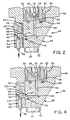
- FIG. 4 and 5 an alternative embodiment of a nozzle assembly 96 is illustrated in which the shim 68 of Figs. 1-3 is eliminated, and a nozzle body 46 and modified nozzle plate 100 are provided.
- the structure in Figs. 5 and 6 which is common to that of the above-described embodiment is identified with the same reference numerals in Figs. 5 and 6 as in Figs. 1-3.
- the nozzle plate 100 of nozzle assembly 96 is identical to the nozzle plate 48 of Figs. 1-3, except that an elongated, longitudinally extending distribution slot 108 is formed in the nozzle plate 48 which extends inwardly from its inner face 70.
- This distribution slot 108 has a lower portion 110, and an upper portion 112 within which the inlet portion 92 of each connector passage 90 in nozzle plate 100 is located.
- the cross sectional area of the distribution slot 108 is less than that of the distribution channel 60 in the nozzle body 46.
- the nozzle body 46 and nozzle plate 100 mount directly to one another, i.e., the face 64 of nozzle body 46 contacts the inner face 70 of nozzle plate 100, such that the outlet 66 of distribution channel 60 in nozzle body 46 intersects the lower portion 110 of distribution slot 108.
- the outlet 66 of distribution channel 60 is located vertically beneath the inlet portion 92 of each connector passage 90 so that adhesive discharged into the distribution slot 108 of nozzle plate 100 and travels vertically upwardly, against the influence of gravity, into the connector passages 90 of nozzle plate 100.
- FIG. 6 A still further embodiment of a nozzle assembly 114 is illustrated in Fig. 6 which comprises a combination of the nozzle body 46 and nozzle plate 48 of Figs. 1 and 2, and a modified shim 116.
- the shim 116 is a rectangular plate formed with an elongated distribution slot 118 having an upper portion 120 and a lower portion 122, instead of a number of oval, vertical slots 78 as in shim 68 of Figs. 1-3.
- the distribution slot 118 preferably has a smaller cross sectional area than that of the distribution channel 60 in the nozzle body 46.
- the lower portion 122 of distribution slot 118 communicates with the outlet 66 of distribution channel 60 in the same relative position as with the lower portion 80 of slots 78 in shim 68, and the upper portion 120 of distribution slot 118 connects to the inlet portion 92 of each connector passage 90 in the nozzle plate 48.
- the same type of flow path for the adhesive is obtained in the nozzle assembly 114 of Fig. 6 as in the previously described embodiments of Figs. 1-3 and 4-5, wherein the adhesive must flow vertically upwardly against the influence of gravity in the course of passage between the nozzle body 46 or 99 and into the connector passages 90 of nozzle plate 48.
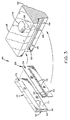
- a nozzle assembly 130 is illustrated in Fig. 7 which includes the same nozzle plate 100 of Figs. 4 and 5 mounted to a modified nozzle body 132.
- the nozzle body 46 of Figs. 1-6 has a tapered, external configuration similar to that disclosed in U.S. Patent No. 5,027,976 to Scholl et al, owned by the assignee of this invention.
- the nozzle body 132 differs from that design in that it does not have such a tapered external configuration, except for an upwardly tapered bottom surface 134 as depicted in Fig. 7. Additionally, the nozzle body 132 is formed with an internal adhesive flow path wherein the connector passage 59 of the previous embodiments is eliminated.
- the internal flow path of this embodiment includes a vertically oriented supply passage 136 which intersects a longitudinal, generally horizontally disposed distribution channel 138 extending inwardly from the inner face 140 of nozzle body 132.
- This inner face 140 abuts the face 70 of nozzle plate 100 so that the outlet 142 of distribution channel 138 is connected to the lower portion 110 of the distribution slot 108 in nozzle plate 100.
- a vertical flow path is thus created between the distribution channel 138 in the nozzle body 132, and the inlet portion 92 of each connector passage 90 in the nozzle plate 100.
- the cross sectional area of the distribution channel 138 in the nozzle body 132 is greater than the cross sectional area of the distribution slot in nozzle plate 100.
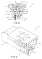
- FIGs. 8 and 9 A still further embodiment of a nozzle assembly 150 is illustrated in Figs. 8 and 9 which has a tapered external configuration similar to that disclosed in U.S. Patent No. 5,027,976 to Scholl et al, owned by the assignee of this invention.
- the nozzle assembly 150 of this embodiment differs from those described above in that no nozzle plate 48 or 100 is employed. Instead, the nozzle assembly 150 includes a nozzle body 152 which directly mounts a number of nozzle tips 84.
- the upper portion of nozzle body 152, and its connection to the dispenser 12, are identical to that described above in the previous embodiments and the same reference numbers are used to depict structure common to that described above.
- the discharge orifice 26 of the dispenser 10 is connected to a feed passage 154 which extends vertically downwardly within nozzle body 152 at an angle, preferably of about 12°, with respect to the longitudinal axis of the plunger 28 and discharge orifice 26.
- the feed passage 154 is connected at approximately the midpoint of a distribution bore 156 which extends longitudinally along the entire length of the nozzle body 152. Plugs or dowels (not shown) are brazed to the nozzle body 152 at each end of the distribution bore 156 to form a seal thereat.
- the nozzle body 152 is formed with a number of substantially vertically oriented discharge passageways 158 each having an inlet portion 160 and a threaded outlet portion 162. Each of the threaded outlet portions 162 of the discharge passageways 158 mounts a nozzle tip 84 of the type described above.
- the inlet portion 160 of each discharge passageway 158 is connected to one end of a connector bore 164. These connector bores 164 extend from one face of the nozzle body 152, where they are plugged by a rod or dowel 166 brazed to the nozzle body 152, and intersect the distribution bore 156.
- Each of the connector bores 164 extends vertically upwardly from the distribution bore 156 to the inlet portion 160 of a discharge passageway 158 at an angle of approximately 15° relative to horizontal as viewed in Fig. 8. Adhesive introduced from the feed passage 154 into the distribution bore 156 therefore travels vertically upwardly along the connector bores 164 to the inlet portion 160 of each discharge passageway 158.
- both the connector bore 164 and inlet portion 160 of discharge passageways 158 have a smaller cross sectional area than the cross sectional area of the distribution bore 156.
- An important aspect of this invention is a capability to avoid the formation of "cut off drool" from the nozzle tips 84, i.e., thin, elongated strands or strings of adhesive, particularly when the flow of adhesive from the dispenser 10 is alternately turned on and off. It is believed that two structural aspects of each of the nozzle assemblies 44, 96, 114, 130 and 150 herein account for the substantial elimination of cut off drool in this invention. For purposes of discussion, reference is made to the nozzle assembly 44 depicted in Figs. 1 and 2, it being understood that the nozzle assemblies 96, 114, 130 and 150 operate in essentially the identical manner.
- an adhesive flow path is formed in the nozzle body 46 and nozzle plate 48 between the discharge orifice 26 of extension 22 and the discharge outlet 88 of each nozzle tip 84.
- Adhesive is introduced into the feed passageway 56 of nozzle body 46 from the extension 22 and flows through the horizontal connector passage 59 into the elongated distribution channel 60 at the face 64 of nozzle body 46.
- the adhesive is emitted from the outlet 66 of the distribution channel 60 and flows vertically upwardly along the individual slots 78 in the shim 68 to the inlet portion 92 of each discharge passage 90 formed in the nozzle plate 48.
- the adhesive then enters the vertical portion 94 of each discharge passage 90 and is transferred vertically downwardly to the through-bore 86 of each nozzle tip 84.
- the adhesive is ejected from the discharge outlet 88 of each nozzle tip 84 to form a plurality of thin, closely spaced extruded beads of adhesive (not shown).
- the pressure applied to the adhesive stream to force it through nozzle body 46 and nozzle plate 48 is eliminated, but adhesive nevertheless remains along essentially the entire flow path through the nozzle body 46 and nozzle plate 48 to each of the nozzle tips 84. It is believed that leakage or drooling of this adhesive from the nozzle tips 84 is substantially eliminated by the construction of nozzle assembly 44 for several reasons.
- the distribution channel 60 formed in nozzle body 46 is located vertically below the inlet portion 92 of each connector passage 90 in nozzle plate 48. This same vertical flow path for the adhesive is present in the nozzle assemblies 96, 114, 130 and 150 of Figs.
- the reduction in cross sectional area of the slots 78 in shim 68 and the inlet portion 92 of connector passages 90 results in an increase in velocity of the adhesive as it is transmitted from the nozzle body 46 to and through the nozzle plate 48.
- the "machineability" or ability to shear is enhanced as velocity is increased.
- the adhesive streams flowing through each of the nozzle tips 84 are more readily and cleanly sheared when the flow of adhesive from the dispenser 10 is intermittently interrupted.
- such adhesive streams within nozzle tips 84 tend to shear at least some distance upstream from their discharge outlets 88 thus producing a gap or space between the adhesive and such discharge outlets 88.
- nozzle assemblies 96, 114, 130 and 150 function in essentially the same manner as described above in connection with nozzle assembly 44.
- a flow path is created wherein the adhesive must flow vertically upwardly in the course of passage between the nozzle body and nozzle plate.
- a reduction in the cross sectional area of the flow path is formed, at least up to and through the discharge passageways, so that the velocity of the adhesive is increased through the nozzle plate to provide for better shearing of the adhesive when flow from the dispenser 10 is intermittently interrupted.
- the supply passage 130 has a diameter of 2.39 mm (.094 inches) and the distribution channel 138 connected to supply passage 136 is preferably formed with a diameter of 2.39 mm (.094 inches).
- the nozzle plate 100 is formed with a distribution slot 142 having a vertical height as depicted in Fig. 7 of 4.39 mm (.173 inches) and a depth of 0.76 mm (.030 inches).
- the distribution slot 142 is connected to the inlet portion 92 of connector passage 90 within nozzle plate 100.
- This inlet portion 92 has a diameter of 0.76 mm (.030 inches) and connects to an outlet passage 94 having a diameter of 1.02 mm (.040 inches).
- the outlet portion 94 of connector passage 90 connects to the throughbore 86 of nozzle tip 84.
- the diameter of the throughbore 86 and the discharge outlet 88 of nozzle tip 84 is in the range of 0.46 to 0.53 mm (.018 to .021 inches).
- the vertical distance from the center of distribution channel 138 in nozzle body 132, and the center of the inlet portion 92 of connector passage 90 is 2.23 mm (.088 inches). It should be understood that the dimensions given above are approximate and subject to variation due to tolerances and the like.
- a nozzle assembly 130 with the above-identified dimensions has been run with each of the following adhesive materials and application conditions.
- the nozzle assembly 130 is operated intermittently with little or no formation of cut off drool from the nozzle tips 84.
- the viscosity of the adhesive materials varied from 950 cps to 1450 cps. It is contemplated that adhesive materials having a higher viscosity, such as rubber-based adhesives with viscosities on the order of 2,000 cps, may require at least some modification of the dimensions of nozzle assembly 130. For example, it is contemplated that higher viscosity in adhesives would require an increase in the dimensions of the discharge outlet 88 in nozzle tip 84, the diameter of the inlet portion 92 of connector passage 90 and/or the depth of distribution slot 142 in the nozzle plate 100 in order to obtain the desired flow rate of adhesive through the nozzle assembly 130 without creating cut off drool during intermittent operation. It is intended that the invention should not be limited to the particular embodiment disclosed as the best mode contemplated for carrying out this invention.
Landscapes
- Coating Apparatus (AREA)
- Nozzles (AREA)
- Application Of Or Painting With Fluid Materials (AREA)
Claims (10)
- Appareil permettant de délivrer une pluralité de perles d'une matière, comprenant un distributeur (10) muni d'un alésage (18) qui possède un orifice de sortie (26) permettant de délivrer la matière, et des moyens formant valve (28, 30) mobiles par rapport audit orifice de sortie (26), entre une position ouverte qui permet la décharge de la matière et une position fermée qui empêche cette décharge, une buse (44, 96, 114, 130, 150) possédant un corps de buse (46, 98, 132, 152) qui est monté sur ledit distributeur (10) et qui communique avec l'orifice de sortie (26) dudit alésage (18) et avec ledit distributeur (10), ledit corps de buse (46, 98, 132, 152) étant muni d'un long canal de distribution (60, 138, 156) qui possède une certaine aire en section transversale et un passage d'alimentation de décharge (56, 59, 138, 164) qui relie ledit canal de distribution (60, 138, 156) audit orifice de sortie (26) dudit distributeur (10);un plateau à buses (48, 100) muni d'un certain nombre de passages de décharge (90, 158), qui ont chacun une partie d'entrée (92, 160) et un orifice de décharge (88, 162), les orifices de décharge (88, 162) formant le point de sortie d'un parcours de fluide, lesdits orifices de décharge (88, 162) desdits passages de décharge (90, 158) étant latéralement écartés desdits moyens formant valve mobiles (28, 30) et dudit alésage (18), etledit corps de buse (46, 98, 132, 152) étant muni de moyens de transfert (78, 108, 164) permettant de diriger la matière, à l'encontre de l'influence de la gravité, à partir dudit passage d'alimentation de décharge (56, 59, 138, 164) pour la faire pénétrer dans ladite entrée de chacun desdits passages de décharge (90, 158), ce grâce à quoi la matière est retenue dans le passage d'alimentation de décharge (56, 59, 138, 164) et dans les moyens de transfert (78, 108, 164) du parcours du fluide, et le passage d'alimentation de décharge (56, 59, 138, 164), les passages de décharge (90, 158) et les moyens de transfert (78, 108, 164) restent en communication fluidique lorsque les moyens formant valve mobiles (28, 30) sont en position ouverte et lorsque les moyens formant valve (28, 30) sont en position fermée,
caractérisé en ce que chacune desdites parties d'entrée (92, 160) possède une aire en section transversale qui est plus petite que l'aire en section transversale dudit passage d'alimentation de décharge (56, 59, 138, 164)et en ce que, en cours d'utilisation, lesdites parties d'entrée (92, 160) desdits passages de décharge (90, 158) sont situées au-dessus, dans la direction verticale, dudit passage d'alimentation de décharge (59, 138, 164). - Appareil selon la revendication 1,
caractérisé en ce que lesdits moyens de transfert comprennent un certain nombre de passages de raccordement (164) inclinés vers le haut dans la direction verticale, ayant chacun une extrémité inférieure reliée audit alésage de distribution et une extrémité supérieure reliée à ladite entrée de l'un desdits passages de décharge. - Appareil selon la revendication 1,
caractérisé en ce que les passages de décharge (90, 158) sont écartés les uns des autres dans la direction longitudinale, le long de l'alésage de distribution, chacun desdits passages de décharge étant muni d'une partie de sortie sur laquelle est montée une pointe de buse. - Appareil selon la revendication 1,
caractérisé en ce que le corps de buse (46, 98, 132, 152) est muni d'un canal de distribution (60, 138, 156), orienté sensiblement horizontalement et comportant ledit orifice de sortie du corps de buse (46, 98, 132, 162), et ledit plateau à buses (48, 100) comprenant en outre un certain nombre de pointes de buse (84) qui contiennent chacune un alésage traversant ayant un orifice d'entrée et un orifice de décharge, et où la partie d'entrée de chaque passage de décharge est orientée sensiblement horizontalement, tandis que la partie de sortie de chaque passage de décharge est orientée sensiblement verticalement et est reliée à l'une desdites entrées desdites pointes de buse. - Appareil selon la revendication 1,
caractérisé en ce que ledit corps de buse (46, 98, 132, 152) comporte une surface, ladite sortie de ladite trajectoire d'écoulement interne comprenant un long canal de distribution qui s'étend dans la direction longitudinale, le long dudit corps de valve (46, 98, 132, 152), et vers l'intérieur à partir de ladite surface dudit corps de buse (46, 98, 132, 152), ledit canal de distribution ayant un orifice de sortie au niveau de ladite surface dudit corps de valve. - Appareil selon les revendications 4 ou 5,
caractérisé en ce que lesdits moyens de transfert (78, 108) comprennent une cale d'épaisseur (68) qui est intercalée entre ledit corps de valve (46, 98, 132) et ledit plateau à buses (48, 100), ladite cale d'épaisseur (68) étant munie d'un certain nombre de fentes orientées sensiblement verticalement, qui ont chacune une extrémité inférieure reliée audit orifice de sortie dudit canal de dIstribution et une extrémité supérieure reliée à ladite partie d'entrée de l'un desdits passages de décharge. - Appareil selon la revendication 1,
caractérisé en ce que ledit corps de buse (46, 98, 132, 152) comporte une face, ladite trajectoire d'écoulement interne comportant un passage d'alimentation orienté verticalement, conçu pour recevoir une matière thermoplastique, un long canal de distribution s'étendant dans la direction longitudinale le long dudit corps de buse, et vers l'intérieur à partir de ladite face de ce dernier, et un passage de raccordement qui relie ledit passage d'alimentation et ledit canal de distribution. - Appareil selon les revendications 4 ou 7,
caractérisé en ce que lesdits moyens de transfert (78, 108) comprennent une cale d'épaisseur (68) qui est intercalée entre ledit corps de valve (46, 98, 132) et ledit plateau à buses (48, 100), ladite cale d'épaisseur (68) étant munie d'une longue fente dont l'extrémité inférieure est reliée audit canal de distribution (60, 138) aménagé dans ledit corps de valve (46, 98, 132), et l'extrémité supérieure est reliée à ladite partie d'entrée de chacun desdits passages de décharge (90) aménagés dans ledit plateau à buses (48, 100). - Appareil selon la revendication 1,
caractérisé en ce que ledit corps de valve (46, 98, 132) est muni d'une première surface et ledit plateau à buses (48, 100) est muni d'une deuxième surface, qui sont en butée l'une contre l'autre, ladite trajectoire d'écoulement interne comportant un canal de distribution (60, 138) qui s'étend vers l'intérieur à partir de ladite première surface dudit corps de valve (46, 98, 132), lesdits moyens de transfert (78, 108) comprenant une longue fente qui s'étend vers l'intérieur à partir de ladite deuxième surface dudit plateau à buses (48, 100) et dont l'extrémité inférieure est reliée audit canal de distribution (60, 138) aménagé dans ledit corps de valve (46, 98, 132), et l'extrémité supérieure est reliée à ladite partie d'entrée de chacun desdits passages de décharge (90). - Appareil selon la revendication 4,
caractérisé en ce que ledit corps de valve (46, 98, 132) est muni d'une première surface et ledit plateau à buses (48, 100) est muni d'une deuxième surface, qui sont en butée l'une contre l'autre, lesdits moyens de transfert (78, 108) comprenant une longue fente qui s'étend vers l'intérieur à partir de ladite deuxième surface dudit plateau à buses (48, 100) et dont l'extrémité inférieure est reliée audit canal de distribution (60, 138) aménagé dans ledit corps de valve (46, 98, 132), et l'extrémité supérieure est reliée à ladite partie d'entrée de chacun desdits passages de décharge (90).
Applications Claiming Priority (2)
| Application Number | Priority Date | Filing Date | Title |
|---|---|---|---|
| US78690191A | 1991-11-01 | 1991-11-01 | |
| US786901 | 1991-11-01 |
Publications (2)
| Publication Number | Publication Date |
|---|---|
| EP0539971A1 EP0539971A1 (fr) | 1993-05-05 |
| EP0539971B1 true EP0539971B1 (fr) | 1998-01-14 |
Family
ID=25139899
Family Applications (1)
| Application Number | Title | Priority Date | Filing Date |
|---|---|---|---|
| EP92118486A Expired - Lifetime EP0539971B1 (fr) | 1991-11-01 | 1992-10-29 | Méthode et appareil pour délivrer des cordons multiples d'un liquide visqueux |
Country Status (7)
| Country | Link |
|---|---|
| US (1) | US5335825A (fr) |
| EP (1) | EP0539971B1 (fr) |
| JP (1) | JPH05212335A (fr) |
| AU (1) | AU658456B2 (fr) |
| CA (1) | CA2081499A1 (fr) |
| DE (1) | DE69224032T2 (fr) |
| TW (1) | TW260626B (fr) |
Families Citing this family (30)
| Publication number | Priority date | Publication date | Assignee | Title |
|---|---|---|---|---|
| ATE172387T1 (de) * | 1994-02-12 | 1998-11-15 | Johannes Zimmer | Vorrichtung zum zuführen einer substanz an eine auftragungsstelle, verfahren zur substanzzuführung und zum reinigen der vorrichtung sowie verfahren zur herstellung der vorrichtung und hilfsvorrichtung zum reinigen der vorrichtung |
| CA2159952A1 (fr) * | 1994-10-31 | 1996-05-01 | Paul Schmidt | Distributeur a ajutage plie |
| US6451409B1 (en) * | 1995-10-17 | 2002-09-17 | Robert F. Lassiter | Roofing material with integrally formed nail tabs |
| US5806720A (en) * | 1996-07-19 | 1998-09-15 | Illinois Tool Works Inc. | Multi position palletizer head for adhesive supply unit |
| JPH1099756A (ja) * | 1996-10-01 | 1998-04-21 | Fuji Mach Mfg Co Ltd | 接着剤ディスペンサ |
| IT1311872B1 (it) * | 1999-11-16 | 2002-03-19 | Hip High Ind Performances Srl | Testata di spalmatura,particolarmente per materiale termoplastico. |
| US6695923B1 (en) | 2000-11-21 | 2004-02-24 | Sealant Equipment & Engineering, Inc. | Multiple orifice applicator system and method of using same |
| US20030131791A1 (en) * | 2000-11-21 | 2003-07-17 | Schultz Carl L. | Multiple orifice applicator system and method of using same |
| JP3957640B2 (ja) * | 2002-02-21 | 2007-08-15 | アイシン化工株式会社 | 幅広スリットノズル及び幅広スリットノズルによる塗装方法 |
| US20050015050A1 (en) * | 2003-07-15 | 2005-01-20 | Kimberly-Clark Worldwide, Inc. | Apparatus for depositing fluid material onto a substrate |
| US7052548B2 (en) * | 2004-04-22 | 2006-05-30 | Nordson Corporation | Angled manifold and dispensing apparatus |
| US20050268845A1 (en) * | 2004-06-03 | 2005-12-08 | Nordson Corporation | Apparatus and nozzle plate for dispensing liquid material |
| US20050271806A1 (en) * | 2004-06-03 | 2005-12-08 | Nordson Corporation | Dispenser and method for non-contact dispensing of adhesive |
| FR2872717B1 (fr) | 2004-07-12 | 2006-09-15 | Itw Surfaces & Finitions Sa | Pistolet de pulverisation automatique comprenant un corps de pulverisation monte sur une embase d'alimentation |
| DE102004058542A1 (de) * | 2004-12-03 | 2006-06-08 | Nordson Corporation, Westlake | Rotationsauftragskopf und Etikettieranlage zum Aufbringen von Etiketten |
| JP4606157B2 (ja) * | 2004-12-27 | 2011-01-05 | 大日本印刷株式会社 | ダイヘッド |
| US7414532B2 (en) * | 2005-04-20 | 2008-08-19 | Nordson Corporation | Method of attaching RFID tags to substrates |
| JP2008543557A (ja) * | 2005-06-23 | 2008-12-04 | アクゾ ノーベル コーティングス インテルナショナール ベー.ファオ. | ディスペンサー |
| US7771556B2 (en) * | 2005-07-01 | 2010-08-10 | Nordson Corporation | Apparatus and process to apply adhesive during labeling operations |
| JP4835920B2 (ja) * | 2006-01-30 | 2011-12-14 | 東洋製罐株式会社 | 粘稠物の環状塗布方法およびその装置 |
| US8171973B2 (en) * | 2008-01-29 | 2012-05-08 | Nordson Corporation | Nozzle and related apparatus and method for dispensing molten thermoplastic material |
| TW201036709A (en) * | 2009-04-10 | 2010-10-16 | Manz Intech Machines Co Ltd | Liquid screen forming apparatus and liquid screen forming method |
| US9120190B2 (en) | 2011-11-30 | 2015-09-01 | Palo Alto Research Center Incorporated | Co-extruded microchannel heat pipes |
| US10371468B2 (en) | 2011-11-30 | 2019-08-06 | Palo Alto Research Center Incorporated | Co-extruded microchannel heat pipes |
| US8875653B2 (en) * | 2012-02-10 | 2014-11-04 | Palo Alto Research Center Incorporated | Micro-extrusion printhead with offset orifices for generating gridlines on non-square substrates |
| US9283579B2 (en) * | 2013-03-12 | 2016-03-15 | Illinois Tool Works Inc. | Variable volume hot melt adhesive dispensing nozzle or die assembly with choke suppression |
| JP6178185B2 (ja) * | 2013-09-24 | 2017-08-09 | 積水化学工業株式会社 | スリットノズル |
| DE102014212940A1 (de) | 2014-07-03 | 2016-01-07 | Fraunhofer-Gesellschaft zur Förderung der angewandten Forschung e.V. | Modul, System und Verfahren zum Auftragen eines viskosen Mediums auf eine Oberfläche und Verfahren zum Herstellen des Moduls |
| AT519001B1 (de) * | 2016-11-04 | 2018-03-15 | Ka Group Man Gmbh | Düsenvorrichtung |
| JP2021154195A (ja) * | 2020-03-26 | 2021-10-07 | ノードソン コーポレーションNordson Corporation | ノズル、接着剤塗布ヘッド、接着剤塗布装置及びおむつ製造方法 |
Family Cites Families (24)
| Publication number | Priority date | Publication date | Assignee | Title |
|---|---|---|---|---|
| US3126574A (en) * | 1964-03-31 | Plow type glue gun | ||
| US1946339A (en) * | 1931-06-25 | 1934-02-06 | Napier & Son Ltd | Fuel injection device for internal combustion engines |
| US2414873A (en) * | 1940-08-02 | 1947-01-28 | Union Carbide & Carbon Corp | Multiflame welding apparatus |
| US2697446A (en) * | 1951-04-07 | 1954-12-21 | Armour & Co | Filling nozzle assembly |
| US2957489A (en) * | 1958-06-25 | 1960-10-25 | Phillips Petroleum Co | Anti-drip trap for loading spout |
| US3327680A (en) * | 1964-02-06 | 1967-06-27 | Peters Mach Co | Hot melt gluing machine |
| US3570725A (en) * | 1968-11-15 | 1971-03-16 | Nordson Corp | Applicator having a fixed module with static parts and a removable module with moving parts |
| US3849241A (en) * | 1968-12-23 | 1974-11-19 | Exxon Research Engineering Co | Non-woven mats by melt blowing |
| US3788561A (en) * | 1972-08-10 | 1974-01-29 | Nordson Corp | Apparatus for employing seals to closures for containers |
| US3840158A (en) * | 1972-10-17 | 1974-10-08 | Nordson Corp | Modular applicator system |
| DE2254033A1 (de) * | 1972-11-04 | 1974-05-16 | Paal Hans | Vorrichtung zum punktweisen auftragen eines klebstoffes |
| US4220114A (en) * | 1978-09-22 | 1980-09-02 | Radowicz Richard D | Applicator head for adhesive application system |
| US4550681A (en) * | 1982-10-07 | 1985-11-05 | Johannes Zimmer | Applicator for uniformly distributing a flowable material over a receiving surface |
| US4534388A (en) * | 1983-06-07 | 1985-08-13 | Pall Corporation | Dispersion system and method |
| JPS60143866A (ja) * | 1983-12-29 | 1985-07-30 | Konishiroku Photo Ind Co Ltd | 塗布方法及びその装置 |
| US4572435A (en) * | 1984-05-30 | 1986-02-25 | Owens-Corning Fiberglas Corporation | Foamable liquid distributing means |
| US4658991A (en) * | 1984-10-23 | 1987-04-21 | Minnesota Mining And Manufacturing Company | Hand pressure attachment for use on thermoplastic dispensing device |
| DE8533284U1 (de) * | 1985-11-26 | 1986-02-06 | Meltex Verbindungstechnik GmbH, 2120 Lüneburg | Schlitzdüse |
| US4687137A (en) * | 1986-03-20 | 1987-08-18 | Nordson Corporation | Continuous/intermittent adhesive dispensing apparatus |
| US4735169A (en) * | 1986-09-03 | 1988-04-05 | Nordson Corporation | Adhesive applicator assembly |
| US4774109A (en) * | 1987-07-21 | 1988-09-27 | Nordson Corporation | Method and apparatus for applying narrow, closely spaced beads of viscous liquid to a substrate |
| US5162121A (en) * | 1988-01-30 | 1992-11-10 | Toyo Seikan Kaisha, Ltd. | Apparatus for extruding multiple synthetic resins |
| US5024709A (en) * | 1990-01-22 | 1991-06-18 | Slautterback Corporation | Contact-free method of forming sift-proof seals |
| US5027976A (en) * | 1989-10-10 | 1991-07-02 | Nordson Corporation | Multi-orifice T-bar nozzle |
-
1992
- 1992-10-27 CA CA002081499A patent/CA2081499A1/fr not_active Abandoned
- 1992-10-29 EP EP92118486A patent/EP0539971B1/fr not_active Expired - Lifetime
- 1992-10-29 DE DE69224032T patent/DE69224032T2/de not_active Expired - Fee Related
- 1992-10-30 JP JP4293556A patent/JPH05212335A/ja not_active Withdrawn
- 1992-10-30 AU AU27473/92A patent/AU658456B2/en not_active Ceased
- 1992-11-10 TW TW081108972A patent/TW260626B/zh active
-
1993
- 1993-09-13 US US08/120,638 patent/US5335825A/en not_active Expired - Fee Related
Also Published As
| Publication number | Publication date |
|---|---|
| US5335825A (en) | 1994-08-09 |
| JPH05212335A (ja) | 1993-08-24 |
| DE69224032T2 (de) | 1998-04-30 |
| CA2081499A1 (fr) | 1993-05-02 |
| TW260626B (fr) | 1995-10-21 |
| EP0539971A1 (fr) | 1993-05-05 |
| AU658456B2 (en) | 1995-04-13 |
| DE69224032D1 (de) | 1998-02-19 |
| AU2747392A (en) | 1993-05-06 |
Similar Documents
| Publication | Publication Date | Title |
|---|---|---|
| EP0539971B1 (fr) | Méthode et appareil pour délivrer des cordons multiples d'un liquide visqueux | |
| US4969602A (en) | Nozzle attachment for an adhesive dispensing device | |
| US5292068A (en) | One-piece, zero cavity nozzle for swirl spray of adhesive | |
| JP3670334B2 (ja) | 流体塗布機 | |
| US4911956A (en) | Apparatus for spraying droplets of hot melt adhesive | |
| US6890167B1 (en) | Meltblowing apparatus | |
| US6540831B1 (en) | Method and apparatus for applying a controlled pattern of fibrous material to a moving substrate | |
| CA1329065C (fr) | Methode et appareil servant a distribuer des gouttelettes d'adhesif thermoplastique en fusion | |
| US4774109A (en) | Method and apparatus for applying narrow, closely spaced beads of viscous liquid to a substrate | |
| AU620920B2 (en) | Nozzle attachment for an adhesive spray gun | |
| US4844004A (en) | Method and apparatus for applying narrow, closely spaced beads of viscous liquid to a substrate | |
| US5740963A (en) | Self-sealing slot nozzle die | |
| US4721252A (en) | Hot-melt sputtering apparatus | |
| EP0422399A2 (fr) | Base en forme de T à plusieurs orifices | |
| US6368409B1 (en) | Electrostatic dispensing apparatus and method | |
| US5238190A (en) | Offset nozzle assembly | |
| JPS62129177A (ja) | 液状粘着剤塗布装置 | |
| US4796813A (en) | Viscous fluid spraying apparatus having a unitary nozzle |
Legal Events
| Date | Code | Title | Description |
|---|---|---|---|
| PUAI | Public reference made under article 153(3) epc to a published international application that has entered the european phase |
Free format text: ORIGINAL CODE: 0009012 |
|
| AK | Designated contracting states |
Kind code of ref document: A1 Designated state(s): CH DE FR IT LI |
|
| 17P | Request for examination filed |
Effective date: 19931018 |
|
| 17Q | First examination report despatched |
Effective date: 19940311 |
|
| GRAG | Despatch of communication of intention to grant |
Free format text: ORIGINAL CODE: EPIDOS AGRA |
|
| GRAG | Despatch of communication of intention to grant |
Free format text: ORIGINAL CODE: EPIDOS AGRA |
|
| GRAH | Despatch of communication of intention to grant a patent |
Free format text: ORIGINAL CODE: EPIDOS IGRA |
|
| GRAH | Despatch of communication of intention to grant a patent |
Free format text: ORIGINAL CODE: EPIDOS IGRA |
|
| GRAA | (expected) grant |
Free format text: ORIGINAL CODE: 0009210 |
|
| AK | Designated contracting states |
Kind code of ref document: B1 Designated state(s): CH DE FR IT LI |
|
| REG | Reference to a national code |
Ref country code: CH Ref legal event code: EP |
|
| REF | Corresponds to: |
Ref document number: 69224032 Country of ref document: DE Date of ref document: 19980219 |
|
| ITF | It: translation for a ep patent filed | ||
| REG | Reference to a national code |
Ref country code: CH Ref legal event code: NV Representative=s name: PATENTANWAELTE SCHAAD, BALASS, MENZL & PARTNER AG |
|
| ET | Fr: translation filed | ||
| PLBE | No opposition filed within time limit |
Free format text: ORIGINAL CODE: 0009261 |
|
| STAA | Information on the status of an ep patent application or granted ep patent |
Free format text: STATUS: NO OPPOSITION FILED WITHIN TIME LIMIT |
|
| 26N | No opposition filed | ||
| PGFP | Annual fee paid to national office [announced via postgrant information from national office to epo] |
Ref country code: CH Payment date: 20000921 Year of fee payment: 9 |
|
| PGFP | Annual fee paid to national office [announced via postgrant information from national office to epo] |
Ref country code: FR Payment date: 20011012 Year of fee payment: 10 |
|
| PG25 | Lapsed in a contracting state [announced via postgrant information from national office to epo] |
Ref country code: LI Free format text: LAPSE BECAUSE OF NON-PAYMENT OF DUE FEES Effective date: 20011031 Ref country code: CH Free format text: LAPSE BECAUSE OF NON-PAYMENT OF DUE FEES Effective date: 20011031 |
|
| PGFP | Annual fee paid to national office [announced via postgrant information from national office to epo] |
Ref country code: DE Payment date: 20011214 Year of fee payment: 10 |
|
| REG | Reference to a national code |
Ref country code: CH Ref legal event code: PL |
|
| PG25 | Lapsed in a contracting state [announced via postgrant information from national office to epo] |
Ref country code: DE Free format text: LAPSE BECAUSE OF NON-PAYMENT OF DUE FEES Effective date: 20030501 |
|
| PG25 | Lapsed in a contracting state [announced via postgrant information from national office to epo] |
Ref country code: FR Free format text: LAPSE BECAUSE OF NON-PAYMENT OF DUE FEES Effective date: 20030630 |
|
| REG | Reference to a national code |
Ref country code: FR Ref legal event code: ST |
|
| PG25 | Lapsed in a contracting state [announced via postgrant information from national office to epo] |
Ref country code: IT Free format text: LAPSE BECAUSE OF NON-PAYMENT OF DUE FEES;WARNING: LAPSES OF ITALIAN PATENTS WITH EFFECTIVE DATE BEFORE 2007 MAY HAVE OCCURRED AT ANY TIME BEFORE 2007. THE CORRECT EFFECTIVE DATE MAY BE DIFFERENT FROM THE ONE RECORDED. Effective date: 20051029 |