EP0539955B1 - Ensemble de ressorts, en particulier pour transmission automatique d'un véhicule automobile - Google Patents
Ensemble de ressorts, en particulier pour transmission automatique d'un véhicule automobile Download PDFInfo
- Publication number
- EP0539955B1 EP0539955B1 EP92118439A EP92118439A EP0539955B1 EP 0539955 B1 EP0539955 B1 EP 0539955B1 EP 92118439 A EP92118439 A EP 92118439A EP 92118439 A EP92118439 A EP 92118439A EP 0539955 B1 EP0539955 B1 EP 0539955B1
- Authority
- EP
- European Patent Office
- Prior art keywords
- spring
- spring assembly
- assembly according
- retainers
- retainer
- Prior art date
- Legal status (The legal status is an assumption and is not a legal conclusion. Google has not performed a legal analysis and makes no representation as to the accuracy of the status listed.)
- Expired - Lifetime
Links
Images


Classifications
-
- F—MECHANICAL ENGINEERING; LIGHTING; HEATING; WEAPONS; BLASTING
- F16—ENGINEERING ELEMENTS AND UNITS; GENERAL MEASURES FOR PRODUCING AND MAINTAINING EFFECTIVE FUNCTIONING OF MACHINES OR INSTALLATIONS; THERMAL INSULATION IN GENERAL
- F16F—SPRINGS; SHOCK-ABSORBERS; MEANS FOR DAMPING VIBRATION
- F16F1/00—Springs
- F16F1/02—Springs made of steel or other material having low internal friction; Wound, torsion, leaf, cup, ring or the like springs, the material of the spring not being relevant
- F16F1/04—Wound springs
- F16F1/12—Attachments or mountings
- F16F1/122—Attachments or mountings where coils, e.g. end coils, of the spring are rigidly clamped or similarly fixed
-
- F—MECHANICAL ENGINEERING; LIGHTING; HEATING; WEAPONS; BLASTING
- F16—ENGINEERING ELEMENTS AND UNITS; GENERAL MEASURES FOR PRODUCING AND MAINTAINING EFFECTIVE FUNCTIONING OF MACHINES OR INSTALLATIONS; THERMAL INSULATION IN GENERAL
- F16F—SPRINGS; SHOCK-ABSORBERS; MEANS FOR DAMPING VIBRATION
- F16F1/00—Springs
- F16F1/02—Springs made of steel or other material having low internal friction; Wound, torsion, leaf, cup, ring or the like springs, the material of the spring not being relevant
- F16F1/04—Wound springs
- F16F1/12—Attachments or mountings
- F16F1/125—Attachments or mountings where the end coils of the spring engage an axial insert
-
- F—MECHANICAL ENGINEERING; LIGHTING; HEATING; WEAPONS; BLASTING
- F16—ENGINEERING ELEMENTS AND UNITS; GENERAL MEASURES FOR PRODUCING AND MAINTAINING EFFECTIVE FUNCTIONING OF MACHINES OR INSTALLATIONS; THERMAL INSULATION IN GENERAL
- F16F—SPRINGS; SHOCK-ABSORBERS; MEANS FOR DAMPING VIBRATION
- F16F3/00—Spring units consisting of several springs, e.g. for obtaining a desired spring characteristic
- F16F3/02—Spring units consisting of several springs, e.g. for obtaining a desired spring characteristic with springs made of steel or of other material having low internal friction
- F16F3/04—Spring units consisting of several springs, e.g. for obtaining a desired spring characteristic with springs made of steel or of other material having low internal friction composed only of wound springs
-
- F—MECHANICAL ENGINEERING; LIGHTING; HEATING; WEAPONS; BLASTING
- F16—ENGINEERING ELEMENTS AND UNITS; GENERAL MEASURES FOR PRODUCING AND MAINTAINING EFFECTIVE FUNCTIONING OF MACHINES OR INSTALLATIONS; THERMAL INSULATION IN GENERAL
- F16H—GEARING
- F16H63/00—Control outputs from the control unit to change-speed- or reversing-gearings for conveying rotary motion or to other devices than the final output mechanism
- F16H63/02—Final output mechanisms therefor; Actuating means for the final output mechanisms
- F16H63/30—Constructional features of the final output mechanisms
- F16H63/3023—Constructional features of the final output mechanisms the final output mechanisms comprising elements moved by fluid pressure
- F16H63/3026—Constructional features of the final output mechanisms the final output mechanisms comprising elements moved by fluid pressure comprising friction clutches or brakes
-
- F—MECHANICAL ENGINEERING; LIGHTING; HEATING; WEAPONS; BLASTING
- F16—ENGINEERING ELEMENTS AND UNITS; GENERAL MEASURES FOR PRODUCING AND MAINTAINING EFFECTIVE FUNCTIONING OF MACHINES OR INSTALLATIONS; THERMAL INSULATION IN GENERAL
- F16F—SPRINGS; SHOCK-ABSORBERS; MEANS FOR DAMPING VIBRATION
- F16F2230/00—Purpose; Design features
- F16F2230/0052—Physically guiding or influencing
Definitions
- This invention relates to a spring assembly, e.g. for incorporation in automatic transmission of automotive vehicles and the like, as defined in the first part of Claim 1 and disclosed by US-A-3 782 708 and more particularly to such a spring assembly wherein spring retainers which will be referred to as "retainers" hereafter are formed according to the invention from a synthetic resin material.
- An automatic transmission of an automobile is generally provided with a hydraulic piston mechanism for engaging and disengaging a clutch.
- a spring assembly is mounted on an input shaft for the mechanical return of the piston mechanism.
- a plurality of coil springs are mounted on a single retainer or between a pair of retainers in the known construction of such a spring assembly incorporated in the automatic transmission of the automobile.
- the shown spring assembly is generally called "clutch piston-return spring" which will be referred to as "clutch type.”
- the spring assembly used in the clutch type has usually comprised of a retainer formed from a metal material into a ring shape and a plurality of coil springs disposed annularly so that the springs are directly engaged with an counterpart. Recently. however. increasing number of the type in which the springs are held at both ends between two retainers has been used for the convenience of its treating.
- burring holes are previously formed in the peripheral face of the retainer when the coil springs are mounted on the retainer. One ends of the springs are fit into the respective burring holes and subsequently, burring cylinders are caulked in the respective holes so that the springs can be prevented from falling out the respective holes.
- the retainer is formed from the metal material.
- the number of the coil springs used in the spring assembly depends upon a required spring force. When a strong spring force is required, the wire diameter of each coil spring is increased and its coil diameter is reduced. That is, the outer diameter of each burring cylinder needs to be reduced so that as many burring cylinders as possible are provided on the retainer.
- the thickness of the retainer is increased as the required spring force is increased. It is not easy to caulk the burring cylinders with a small diameter on the thickened retainer. Accordingly, the thickness of the retainer and the number of the burring cylinders cannot be set unrestrictedly in the conventional spring assembly, which reduces freedom in designing.
- a retainer used in the spring assembly of the brake type generally has the construction as shown in FIG. 16.
- the retainer R' is formed generally into the shape of a ring and has four brackets 20 integrally formed on its peripheral edge.
- Each bracket 20 has three mounting portions 21 on which the coil springs not shown in FIG. 16 are mounted respectively and then, the spring assembly is incorporated into the reduction gear mechanism so that the coil springs thus mounted on the retainer are engaged with the counterpart.
- the retainer In the spring assembly of both above-described types, the retainer is required to have no burrs. For this purpose, a barrel polishing is performed for removal of the burrs from the retainer after the burring.
- the barrel polishing results in the problem of warp in the retainer and in particular, that of the brake type.
- the reason for this is that the retainer of the brake type has a diameter larger and a rigidity lower than that of the clutch type. Consequently, a step of remedying the warp needs to be applied to the retainer of the brake type, which increases in the number of assembly steps and lowers the manufacturing efficiency.
- the spring assembly has another problem of a relative angular displacement or distortion caused between the pair of retainers of the clutch type wherein in the coil springs are held between the retainers. A measure needs to be taken against the distortion of the retainers.
- the spring assemblies are usually exclusive parts differing from one type of automobile to another type. Some identification marks need to be put on the spring assemblies in an assembly line.
- the coil springs are usually sprayed with color paints for this purpose. However, the painting work is troublesome and the paint film applied to the coil springs is easy to peel off and the paint film having peeled off the coil springs lowers the purity of a lubrication oil of the hydraulic system, clogging a hydraulic valve.
- an object of the present invention is to provide a spring assembly which can be manufactured at a high manufacturing efficiency and provide an improved degree of freedom in manufacturing the retainers.
- Another object of the invention is to provide a spring assembly provided with distortion preventing means which can be readily formed.
- the present invention provides a spring assembly wherein a plurality of coil springs are provided circumferentially between a pair of generally ring-shaped first and second spring retainers, wherein a plurality of cylindrical mounting protrusions are circumferentially formed on an annular face of at least one of said spring retainers for mounting the coil springs respectively, characterized in that said pair of spring retainers is formed from a synthetic resin material and said a mounting protrusions are integrally formed with at least one of said pair of spring retainers.
- the present invention may provide a spring assembly wherein a plurality of coil springs are provided between a pair of generally ring-shaped first and second spring retainers, characterized in that the spring retainers are formed integrally from a synthetic resin material, that the spring retainers have a plurality of mounting protrusions formed on annular faces thereof facing each other and a plurality of guide protrusions formed on the annular faces thereof so as to correspond to the mounting protrusions, and that the coil springs has one ends mounted on the mounting protrusions of either spring retainer and the other ends fitted to the guide protrusions of the other spring retainer respectively.
- walls be formed on the face of one or each spring retainer so as to surround the mounting protrusions respectively.
- each mounting protrusion be formed into a generally cylindrical shape and the end of each coil spring can be press fitted to outer periphery of each mounting protrusion.
- the retainers When the walls are formed on the retainers so as to surround the respective mounting portions, not only the retainers can be reinforced, but the distortion of the coil springs can be prevented. Consequently, the seating state of each coil spring can be rendered stable. Further, the coil spring can be press fitted to the respective mounting portions so as to be elastically fixed in position when the mounting portions are formed into the cylindrical shape. Consequently, the coil spring mounting work can be improved in the efficiency.
- the invention is applied to a spring assembly S of the clutch type in the first embodiment.
- the spring assembly S comprises first and second retainers R1 and R2 and a plurality of coil springs 1 held between the retainers R1, R2.
- Both retainers R1, R2 are integrally formed from a synthetic resin material such as reinforced plastics into a ring shape and have the same diameter.
- a plurality of mounting portions 2 are provided at equal angular intervals on the peripheral face of each of the retainers R1, R2.
- the mounting portions 2 are integrally formed so as to project from the peripheral faces of the retainers R1, R2 respectively and so as to generally have a circularly trapezoidal shape.
- Each mounting portion 2 has a constricted or narrow portion 3 formed at its root along the periphery.
- the constricted portions 3 prevent the coil springs from falling out of the respective mounting portions 2.
- the constricted port ions 3 are formed by heat caulking the mounting portions 2.
- the constricted portions 3 may or may not be provided.
- the coil springs 1 can be press fitted to the respective mounting portions 2 to be fixed in position when the constricted portions 3 are not provided.
- the mounting portions 2 of the retainer R1 and those of the retainer R2 are out of phase such that the mounting portions 2 protrude alternately from the retainers R1, R2. Accordingly, when the retainers R1, R2 are combined with each other, one ends of the coil springs 1 are fitted to the mounting portions 2 respectively and the other ends of the coil springs 1 whose opposite ends are fitted to the respective mounting portions 2 of either retainer are loosely fitted to guide protrusions T formed on the other retainer respectively. Consequently, perpendicularity of the coil springs 1 to the retainers can be maintained and the buckling of the coil springs 1 can be prevented.
- the spring assembly S constructed as described above is incorporated in the automatic transmission mechanism in the condition that a predetermined load is applied to the coil springs 1 or the coil springs 1 are compressed. In operation, the spring assembly S is displaced by compression and return of the coil springs 1.
- the mounting portions 2 are formed concurrently with the forming of the retainers R1, R2.
- the retainers R1, R2 can be efficiently manufactured since the step for removal of burrs, which step is required in the prior art, is not required.
- the height and the outer diameter of each mounting portion 2 and the like can be set irrespective of the thickness of the retainers since the retainers are molded out of the synthetic resin material. Consequently, the degree of freedom in the design of the spring assembly can be improved.
- the retainers can be readily formed into a shape even where it is difficult to obtain the shape by the metal working. Consequently, the limitations to the forming of the spring assembly can be remarkably reduced.
- the lubricating oil sometimes leaks through the apertures depending upon the structure of the transmission mechanism in which the spring assembly is incorporated.
- the through-apertures are not sometimes allowed to be formed in the spring assembly.
- both ends of the coil springs only abut against the respective retainers in the prior art, which renders the coil springs unstable.
- the spring assembly S can be applied to various types of automatic transmission mechanism and the like since the retainers R1, R2 are not provided with any through-apertures such as the burring apertures.
- each of the retainers R1, R2 can be formed from a colored resin and various kinds of colors can be used in accordance with the types of the spring assembly.
- the spring assemblies need not be sprayed with different color paints so that the identification marks are formed on the spring assemblies. Consequently, the anxiety about the peeling of the paint film can be eliminated and the lubricating oil can be prevented from lowering its cleanness by the paint film.
- the identification of the types of spring assemblies in the assembly line can be improved and a false incorporation of the spring assembly into the transmission mechanism and the like can be prevented from occurring.
- Two kinds of protrusions that is, the mounting portions 2 and the guide protrusions T, are disposed alternately circumferentially on each of the retainers R1. R2 in the first embodiment.
- the coil springs 1 are mounted on the mounting portions 2 of both retainers R1, R2 respectively.
- the retainers R1, R2 are then combined with each other such that the coil springs 1 are projected alternately from the retainers R1, R2.
- only the mounting portions 2 are formed on the retainer R1 and only the guide protrusions T are formed on the other retainer R2 in a second embodiment.
- one ends of the coil springs 1 are fixed to the retainer R1 by heat caulking the mounting portions 2, whereby the coil springs 1 are projected from the retainer R1.
- each guide protrusion T should have a diameter larger than that shown in FIG. 1 so as to be in contact with the inner periphery of the coil spring 1.
- FIG. 4 illustrates a third embodiment of the invention.
- a chamfer 4 is formed on a distal end of each mounting portion 2 over its entire circumference. Accordingly, the insertion of each coil spring 1 can be readily performed since the distal end of each mounting portion 2 is tapered.
- each mounting portion 2 has a spherical distal end 5. Consequently, the insertion of each coil spring 1 can also be performed readily.
- FIG. 6 illustrates a fifth embodiment.
- Each mounting portion 2 has a small diameter portion 6 at the distal end and for example, four ribs 7 radially formed on the peripheral face to extend in the direction of its height.
- each rib 7 is elastically deformed so that its distal end is bent.
- the bending renders the insertion of each coil spring 1 easy and the fixation of each coil spring 1 secured.
- the ribs 7 in FIG. 5 are projected radially, they may be projected tangentially for further enhancement of the bending.
- FIG. 7 illustrates a sixth embodiment.
- each mounting portion 2 is formed into the shape of a polygonal pole.
- FIG. 7 shows the mounting portion 2 formed into the shape of a hexagonal pole, it may be formed into the shape of another polygonal pole such as a triangle, square or pentagonal pole.
- a plurality of metal screws 8 are integrally provided on each retainer by way of an insert molding so as to serve as the mounting portion 2.
- Each metal screw 8 includes a shaft portion 8a having a helical groove and an integral flat head portion 8b.
- a plurality of pins allowing the coil spring to be press fitted may be provided by way of the insert molding so as to serve as the mounting portion.
- a reinforcing metal sheet 9 is integrally provided in each retainer by way of the insert molding.
- a plurality of arcuate reinforcing sheets may be provided at predetermined intervals in each retainer instead of the ring-shaped reinforcing metal sheets.
- FIG. 10 illustrates a ninth embodiment of the invention.
- Reinforcing projections 10 are radially formed between the coil springs 1 on the circumferential face of each of the retainers R1, R2. This construction improves the strength of each retainer and prevents the thickness of each retainer from being unnecessarily increased. This effect is remarkable when the spring assembly of this embodiment is applied to that of the brake type which type tends to lack in the durability.
- FIG. 11 illustrates a tenth embodiment.
- the spring assembly of the tenth embodiment is provided with distortion preventing means.
- a pair of first distortion preventing pieces 11 serving as the distortion preventing means are formed on the outer peripheral edge of the first retainer R1 to be projected toward the side of the second retainer R2.
- the first distortion preventing pieces 11 are positioned so as to correspond to two coil springs 1 at both sides of the three coil springs 1 disposed in sequence.
- These first distortion preventing pieces 11 are integrally formed so as to stand from the outer peripheral edge of the first retainer R1.
- the inner side of each first distortion preventing piece 11 is curved so as to cover half round the corresponding coil spring 1. Accordingly, each first distortion preventing piece 11 also serves to guide expansion and contraction of the corresponding coil spring 1.
- a second distortion preventing piece 12 also serving as the distortion preventing means extends from the second retainer R2 to be interposed between the first distortion preventing pieces 11.
- the second distortion preventing piece 12 also has a curved inner side covering half round the corresponding coil spring 1 in the same manner as in the first distortion preventing pieces 11 though that is not shown in FIG. 11.
- Two distortion preventing means comprising the first and second distortion preventing pieces 11, 12 are disposed symmetrically on the spring assembly S, for example.
- the first and second distortion preventing pieces 11, 12 are provided so as to be overlapped each other in the direction of their heights and so that no gap is circumferentially left between them.
- both distortion preventing pieces 11, 12 are engaged with each other such that the angular displacement between the retainers R1, R2 can be prevented. Furthermore, since the first and second distortion preventing pieces 11, 12 can be formed integrally with the first and second retainers R1, R2 respectively, a special work for the provision of the distortion preventing means is not required though this work is required in the prior art. Consequently, reduction in the manufacturing cost and improvement of the manufacturing efficiency can be expected.
- FIG. 12 illustrates an eleventh embodiment.
- the invention is applied to the spring retainer R having a free end side of each coil spring being engaged with the counterpart.
- cylindrical guide members 13 are formed on the peripheral face of the retainer R.
- the coil springs 1 are inserted in the guide members 13 at a predetermined level respectively.
- the mounting portions 2 are formed on the inner bottom of the guide members 13 respectively.
- the guide members 13 prevent the respective coil spring 1 from bending and falling, thereby holding them in the normal attitude. Consequently, the load applied to the counterpart by the coil springs 1 can be stably maintained at a preselected value.
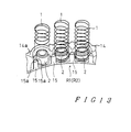
- FIGS. 13 and 14 illustrate a twelfth embodiment.
- the retainers R1, R2 are formed from the synthetic resin into the ring shape.
- the mounting portions 2 are formed on one side face of each retainer at the predetermined intervals for mounting a plurality of coil springs 1 respectively.
- Each mounting portion 2 is formed into a generally cylindrical shape and has a diameter larger than the inner diameter of the coil spring 1 so that the coil spring 1 can be elastically engaged with the mounting portion 2. Consequently, each coil spring 1 is fitted to the outer periphery of the mounting portion 2 by the elastically expansive force of the mounting portion 2 to be fixed in position.
- each mounting portion 2 is cylindrical, it may be prismatic.
- a wall 14 is formed outside the cylindrical mounting portions 2 on the outer periphery of each retainer to be concentric with and to be spaced from the mounting portion 2.
- the wall 14 has circularly arcuate portions formed at the interval corresponding to the wire diameter of the coil spring 1 extending continuously over the whole circumference of the retainer such that the wall 14 is formed into a corrugated shape.
- the wall 14 has a height larger than the retainers R1, R2.
- the wall 14 may be positioned on the inner peripheral side of the retainer or between each coil spring 1 and the adjacent one.
- a projection 15 generally having the shape of a triangle pole is formed on the inner peripheral side of each retainer so as to be positioned between each coil spring 1 and the adjacent one.
- One of three vertexes of each projection 15 is directed toward each ridge portion 14a of the wall 14 formed on the outer peripheral side of each retainer.
- Each projection 15 has left-hand and right-hand sides 15a between which the vertex is positioned. These sides 15a are engageable with the outer periphery of the adjacent coil spring 1.
- the mounting portions 2 for mounting the coil springs 1 are integrally formed on each of the retainers R1, R2.
- the wall 14 is formed outside the cylindrical mounting portions 2 on the outer periphery of each retainer to be concentric with the mounting portion 2 and to have the circularly arcuate portions extending continuously over the whole circumference of the retainer.
- the retainers R1, R2 are reinforced by the respective walls 14 and distortion of each retainer can be prevented. Consequently, the thickness of each retainer can be reduced.
- the distortion at the inner peripheral side of each retainer can be prevented by the projections 15 formed on the inner peripheral side of each retainer at the predetermined intervals. Consequently, each retainer can be maintained in the stable planarity and the seating of the coil springs 1 can be rendered stable.
- each mounting portion 2 is formed into the cylindrical shape and has a diameter larger than the inner diameter of the coil spring 1 so that the coil spring 1 can be elastically engaged with the mounting portion 2. Consequently, the coil springs 1 can be readily fitted to the outer periphery of the mounting portions 2 respectively and the resin mold can be performed advantageously. Additionally, the status of the coil springs 1 fitted to the respective mounting portions 2 can be stabilized and secured, which ensures linearity of the telescopic motion of each coil spring 1.
- FIG. 15 illustrates a thirteenth embodiment.
- a guide protrusion 16 with a predetermined length is formed on either retainer and the end of the coil spring 1 fitted to the mounting portion 2 of the other retainer is fitted to the guide protrusion 16.
- the other construction is the same as described above.
- the guide protrusion 16 can effectively prevent the relative angular displacement caused between the retainers R1, R2, whereby the coil springs 1 can be prevented from bending and falling and held in the normal attitude. Consequently, the load applied to the counterpart by the coil springs 1 can be stably maintained at a preselected value.
- the spring assembly of the invention is applied to that of the clutch type in the foregoing embodiments, it may be applied to the spring assembly of the brake type and the same effect can be achieved in the brake type spring assembly as in that of the clutch type.
Landscapes
- Engineering & Computer Science (AREA)
- General Engineering & Computer Science (AREA)
- Mechanical Engineering (AREA)
- Physics & Mathematics (AREA)
- Fluid Mechanics (AREA)
- Springs (AREA)
Claims (26)
- Ensemble de ressorts dans lequel une pluralité de ressorts hélicoïdaux (1) sont placés circonférentiellement entre une paire de première et deuxième montures de retenue de ressorts (R1, R2) sensiblement annulaires, dans lequel une pluralité de bossages de montage cylindriques sont formés circonférentiellement sur une face annulaire d'au moins une des dites montures de ressorts (R1, R2) pour montage des ressorts hélicoïdaux (1), respectivement,
caractérisé en ce que :la dite paire de montures de ressorts (R1, R2) est fabriquée en une matière de type résine synthétique, etles dits bossages de montage (2) sont formés solidairement avec au moins une des dites deux montures de retenue de ressorts (R1, R2). - Ensemble de ressorts suivant la revendication 1, caractérisé en ce que la dite pluralité de bossages de montage (2) des première et deuxième montures de ressorts (R1, R2) sont mutuellement en regard et les dits bossages de montage d'au moins une des dites montures de ressorts (R1; R2) présentent un contour de la surface cylindrique de manière à venir en prise avec le dit ressort hélicoïdal et à empêcher le ressort hélicoïdal de quitter le bossage.
- Ensemble de ressorts suivant la revendication 1 ou 2, caractérisé en ce que le dit contour de la surface cylindrique des bossages de montage comprend une partie réduite ou étroite (3) formée sur sa racine le long de la périphérie pour venir en prise avec le dit ressort hélicoïdal (1).
- Ensemble de ressorts suivant la revendication 2 ou 3, caractérisé en ce que la dite première monture de ressorts (R1) comprend une pluralité de bossages de guidage (T) formés sur sa face annulaire et agencés en regard des bossages de montage (2) de la deuxième monture de ressorts (R2).
- Ensemble de ressorts suivant la revendication 4, caractérisé en ce que les dits ressorts hélicoïdaux (1) ont une extrémité montée sur les bossages de montage (2) d'une des montures de ressorts (R1, R2) et l'autre extrémité placée sur les bossages de guidage (T) de l'autre monture de ressorts (R1, R2) respectivement.
- Ensemble de ressorts suivant la revendication 4 ou 5, caractérisé en ce que les dits bossages de guidage (T) ont un diamètre plus grand que la périphérie intérieure du ressort hélicoïdal (1).
- Ensemble de ressorts suivant une des revendications 4 à 6, caractérisé en ce que les dits bossages de montage (2) et les dits bossages de guidage (T) sont disposés en alternance circonférentiellement sur chacune des montures (R1, R2).
- Ensemble de ressorts suivant une des revendication 1 à 7, caractérisé en ce que le dit bossage de montage (2) comporte un chanfrein (4) sur l'extrémité distale, sur toute sa circonférence;
- Ensemble de ressorts suivant une des revendications 1 à 7, caractérisé en ce que le dit bossage de montage (2) comporte une extrémité distale sphérique (5).
- Ensemble de ressorts suivant une des revendications 1 à 7, caractérisé en ce que le dit bossage de montage (2) comprend des nervures (7) formées radialement sur la face périphérique et s'étendant dans la direction de la hauteur du bossage.
- Ensemble de ressorts suivant une des revendications 1 à 7, caractérisé en ce que le dit bossage de montage (2) comprend des nervures (7) formées radialement sur la face périphérique de manière à s'étendre dans la direction de sa hauteur et à faire saillie tangentiellement.
- Ensemble de ressorts suivant une des revendications 1 à 7, caractérisé en ce que le dit bossage de montage (2) est en forme de colonnette polygonale.
- Ensemble de ressorts suivant une des revendications 1 à 12, caractérisé en ce qu'une des dites montures de ressorts comprend des bossages de montage sous la forme de vis en métal solidairement prévues sur la dite monture de ressorts (R1, R2).
- Ensemble de ressorts suivant une des revendications 1 à 12, caractérisé en ce que les dites montures de ressorts (R1, R2) comprennent une tôle en métal de renforcement (9) solidairement prévue à l'intérieur.
- Ensemble de ressorts suivant une des revendications 1 à 14, caractérisé en ce que les dites montures de ressorts (R1, R2) comportent des goussets de renforcement (10) formés radialement entre les ressorts hélicoïdaux (1), sur leur face circonférentielle.
- Ensemble de ressorts suivant une des revendications 1 à 14, caractérisé en ce que les dites montures de ressorts (R1, R2) comportent des colonnettes anti-distorsion (11, 12) s'étendant solidairement à partir des montures de ressorts respectives (R1, R2) en regard les unes des autres de sorte que les colonnettes anti-distorsion (11, 12) d'une monture de ressorts (R1, R2) sont en contact avec les colonnettes anti-distorsion (11, 12) de l'autre monture de ressorts (R1, R2) lorsqu'un déplacement angulaire se produit entre les montures de ressorts (R1, R2).
- Ensemble de ressorts suivant la revendication 16, caractérisé en ce que les dites colonnettes anti-distorsion (11, 12) sont formées sur le bord périphérique extérieur des montures de ressorts respectives (R1, R2).
- Ensemble de ressorts suivant une des revendications 16 ou 17, caractérisé en ce que les dits moyens anti-distorsion (11, 12) sont incurvés de manière à couvrir la demi-circonférence du ressort hélicoïdal correspondant (1).
- Ensemble de ressorts suivant une des revendications 1 à 18, caractérisé en ce que des éléments de guidage cylindriques (13) sont formés sur la face périphérique de la monture (R1, R2).
- Ensemble de ressorts suivant une des revendications 1 à 19, caractérisé en ce qu'une paroi (14) est formée solidairement de manière à entourer les bossages de montage (2), respectivement.
- Ensemble de ressorts suivant une des revendications 1 à 20, caractérisé en ce que la dite paroi (14) est formée sur la périphérie extérieure de chaque monture (R1, R2) et comprend des parties en arc de cercle formées à un intervalle correspondant au diamètre d'enroulement du ressort hélicoïdal (1).
- Ensemble de ressorts suivant une des revendications 20 ou 21, caractérisé en ce que la dite paroi (14) est de configuration ondulée et elle a une hauteur plus grande que les montures de ressorts (R1, R2).
- Ensemble de ressorts suivant une des revendications 20 à 22, caractérisé en ce qu'une saillie (15) sensiblement en forme de colonnette triangulaire est formée sur le côté périphérique intérieur de chaque monture de ressorts (R1, R2) tandis que la dite saillie (15) est située entre chaque ressort hélicoïdal (1), et un des sommets de chaque saillie (15) est dirigé vers chaque région de crête (14a) de la paroi (14).
- Ensemble de ressorts suivant une des revendications 20 à 23, caractérisé en ce que les dits bossages de montage (2) ont un diamètre plus grand que le diamètre intérieur du ressort hélicoïdal (1).
- Ensemble de ressorts suivant une des revendications 20 à 24, caractérisé en ce que les dits bossages de montage (2) sont de forme prismatique.
- Ensemble de ressorts suivant une des revendications 1 à 25, caractérisé en ce qu'un bossage de guidage (16) est formé sur une monture quelconque (R1, R2) au lieu de bossages de montage (2), de préférence à la position de 120 degrés.
Applications Claiming Priority (4)
| Application Number | Priority Date | Filing Date | Title |
|---|---|---|---|
| JP314121/91 | 1991-10-30 | ||
| JP31412191A JP3384814B2 (ja) | 1991-10-30 | 1991-10-30 | スプリング組立体 |
| JP245822/92 | 1992-08-21 | ||
| JP24582292A JP3360847B2 (ja) | 1992-08-21 | 1992-08-21 | スプリング組立て体 |
Publications (2)
| Publication Number | Publication Date |
|---|---|
| EP0539955A1 EP0539955A1 (fr) | 1993-05-05 |
| EP0539955B1 true EP0539955B1 (fr) | 1998-02-18 |
Family
ID=26537422
Family Applications (1)
| Application Number | Title | Priority Date | Filing Date |
|---|---|---|---|
| EP92118439A Expired - Lifetime EP0539955B1 (fr) | 1991-10-30 | 1992-10-28 | Ensemble de ressorts, en particulier pour transmission automatique d'un véhicule automobile |
Country Status (3)
| Country | Link |
|---|---|
| US (1) | US5772191A (fr) |
| EP (1) | EP0539955B1 (fr) |
| DE (1) | DE69224457T2 (fr) |
Families Citing this family (36)
| Publication number | Priority date | Publication date | Assignee | Title |
|---|---|---|---|---|
| DE19603248B4 (de) * | 1995-02-03 | 2011-09-22 | Schaeffler Technologies Gmbh & Co. Kg | Drehschwingungsdämpfer |
| JPH1061701A (ja) * | 1996-08-15 | 1998-03-06 | Exedy Corp | コイルスプリング組立体及びダンパー機構 |
| JP3848508B2 (ja) * | 1999-07-19 | 2006-11-22 | 株式会社エクセディ | ダンパー機構 |
| US6481702B1 (en) * | 2000-09-20 | 2002-11-19 | Meritor Heavy Vehicle Systems, Llc | Reduction of coil spring load height variability |
| US6435490B1 (en) * | 2001-02-08 | 2002-08-20 | Lockheed Martin Corporation | Dual hemisphere elastomer mount |
| US6575439B1 (en) * | 2002-02-21 | 2003-06-10 | Barnes Group Inc. | Ring shaped spring device |
| US7021610B2 (en) * | 2002-09-30 | 2006-04-04 | Barnes Group Inc. | Ring shaped spring device |
| JP3926773B2 (ja) * | 2002-10-21 | 2007-06-06 | 株式会社パイオラックス | ばね組立体及びその製造方法 |
| JP4077374B2 (ja) * | 2003-07-02 | 2008-04-16 | 株式会社パイオラックス | ばね組立体の製造方法 |
| JP4077375B2 (ja) * | 2003-07-02 | 2008-04-16 | 株式会社パイオラックス | ばね組立体の製造方法 |
| FR2862355B1 (fr) * | 2003-11-18 | 2006-02-10 | Ecl | Systeme de liaison de deux arbres en translation |
| CN100392279C (zh) * | 2004-07-28 | 2008-06-04 | 陈清欣 | 一种发动机悬置软垫总成 |
| SG157949A1 (en) * | 2004-07-28 | 2010-01-29 | Panasonic Refrigeration Device | System for reducing compressor noise and suspension spring and snubber arrangement therefor |
| JP2009531577A (ja) * | 2006-01-31 | 2009-09-03 | ローベルト ボツシユ ゲゼルシヤフト ミツト ベシユレンクテル ハフツング | 内燃機関に燃料を供給するための高圧ポンプ |
| JP2009068590A (ja) * | 2007-09-12 | 2009-04-02 | Togo Seisakusho Corp | スプリングユニット |
| DE102008009815B4 (de) * | 2008-02-19 | 2016-09-29 | Robert Bosch Gmbh | Rückzugkugel für eine hydrostatische Kolbenmaschine und System aus einer solchen Rückzugskugel und aus einer Vielzahl von Federn |
| JP5448184B2 (ja) * | 2009-06-18 | 2014-03-19 | 株式会社パイオラックス | ばね組立体とその製造方法 |
| US8469844B2 (en) * | 2010-12-28 | 2013-06-25 | Kawasaki Jukogyo Kabushiki Kaisha | Engine with chain tensioner |
| WO2012121072A1 (fr) * | 2011-03-04 | 2012-09-13 | 株式会社パイオラックス | Ensemble ressort |
| ES2408105B1 (es) * | 2011-07-15 | 2014-04-22 | Fco. Javier Porras Vila | Muelles matriuskos antiseísmos, potenciados |
| US9181929B2 (en) * | 2013-03-08 | 2015-11-10 | Rotex Manufacturers And Engineers Private Limited | Actuator with efficient energy accumulation |
| DE102014102515A1 (de) * | 2014-02-26 | 2015-08-27 | Getrag Getriebe- Und Zahnradfabrik Hermann Hagenmeyer Gmbh & Cie Kg | Federpaket, Kupplung und Kupplungsherstellungsverfahren |
| CN106489042B (zh) * | 2014-06-19 | 2019-11-26 | 日本发条株式会社 | 螺旋弹簧组装体 |
| DE102014212701A1 (de) * | 2014-07-01 | 2016-01-07 | Dichtungstechnik G. Bruss Gmbh & Co. Kg | Vorrichtung zur Betätigung einer Kupplung in einem hydraulischen System und Verfahren zur Herstellung einer solchen Vorrichtung |
| EP3020966B1 (fr) * | 2014-11-11 | 2020-01-22 | Danfoss A/S | Machine à piston axial |
| DE102016207019B4 (de) | 2016-04-26 | 2024-09-12 | Schaeffler Technologies AG & Co. KG | Kupplungseinrichtung |
| US9909630B1 (en) * | 2016-08-16 | 2018-03-06 | Ford Global Technologies, Llc | Clutch system |
| US11002042B2 (en) * | 2016-08-16 | 2021-05-11 | Jamell E. Moore | Safety door latch system |
| US10267368B2 (en) * | 2016-12-06 | 2019-04-23 | GM Global Technology Operations LLC | Spring pack assembly for a torque transmitting device |
| US10233980B2 (en) * | 2016-12-13 | 2019-03-19 | GM Global Technology Operations LLC | Spring pack assembly for a torque transmitting device |
| CN107632669B (zh) * | 2017-09-15 | 2020-06-16 | 苏州浪潮智能科技有限公司 | 一种多层扩展卡缓冲支架 |
| EP3741648B1 (fr) | 2018-01-19 | 2024-04-24 | Autoliv Development AB | Volant de direction |
| KR102157883B1 (ko) | 2018-07-17 | 2020-09-21 | 엘지전자 주식회사 | 리니어 압축기 |
| KR102414137B1 (ko) * | 2020-08-20 | 2022-06-28 | 엘지전자 주식회사 | 밀폐형 압축기 |
| DE102021120476B3 (de) * | 2021-08-06 | 2022-08-18 | Schaeffler Technologies AG & Co. KG | Hydraulikanordnung und elektrischer Achsantriebsstrang |
| US11988209B2 (en) * | 2021-12-03 | 2024-05-21 | Hamilton Sundstrand Corporation | Spring retainer for gear pump bearing plate |
Family Cites Families (15)
| Publication number | Priority date | Publication date | Assignee | Title |
|---|---|---|---|---|
| US1205603A (en) * | 1915-11-20 | 1916-11-21 | Joseph Dottl | Spring and frame supporter for motor-cars. |
| GB130393A (en) * | 1917-04-14 | 1919-08-07 | Emile Letord | Spring Suspension Device for Indicating and Registering Instruments. |
| US1937854A (en) * | 1931-11-12 | 1933-12-05 | George O Stratton | Auxiliary spring bumper for vehicles |
| US2104962A (en) * | 1936-08-24 | 1938-01-11 | Borg Warner | Friction clutch |
| US2495920A (en) * | 1945-08-25 | 1950-01-31 | Miner Inc W H | Friction shock absorber |
| US2690845A (en) * | 1949-11-09 | 1954-10-05 | David W Macomber | Shock absorbing means |
| US3394788A (en) * | 1966-05-10 | 1968-07-30 | Dana Corp | Spring loaded clutch |
| US3489255A (en) * | 1968-03-28 | 1970-01-13 | Borg Warner | Clutch with spring retainers |
| US3782708A (en) * | 1971-12-01 | 1974-01-01 | Kuhlman Corp | Spring assembly and methods and machines for the manufacture thereof |
| US4098148A (en) * | 1976-12-08 | 1978-07-04 | Borg-Warner Corporation | Transmission controls |
| DE8319124U1 (de) * | 1983-06-29 | 1987-04-16 | Siemens AG, 1000 Berlin und 8000 München | Vakuumschaltgerät mit einer Einstellvorrichtung für die Vorspannkraft einer Feder |
| US4936432A (en) * | 1987-05-11 | 1990-06-26 | Dana Corporation | Internal assisted clutch components and assembly |
| JP2557438Y2 (ja) * | 1989-02-22 | 1997-12-10 | 光洋精工株式会社 | 一方クラッチの保持器 |
| JPH0320131A (ja) * | 1989-06-16 | 1991-01-29 | Nhk Spring Co Ltd | ばね装置 |
| US5073156A (en) * | 1989-12-04 | 1991-12-17 | Ford Motor Company | Nonsynchronous automatic transmission with overdrive |
-
1992
- 1992-10-28 EP EP92118439A patent/EP0539955B1/fr not_active Expired - Lifetime
- 1992-10-28 DE DE69224457T patent/DE69224457T2/de not_active Expired - Fee Related
-
1996
- 1996-12-04 US US08/760,419 patent/US5772191A/en not_active Expired - Fee Related
Also Published As
| Publication number | Publication date |
|---|---|
| EP0539955A1 (fr) | 1993-05-05 |
| US5772191A (en) | 1998-06-30 |
| DE69224457D1 (de) | 1998-03-26 |
| DE69224457T2 (de) | 1998-06-25 |
Similar Documents
| Publication | Publication Date | Title |
|---|---|---|
| EP0539955B1 (fr) | Ensemble de ressorts, en particulier pour transmission automatique d'un véhicule automobile | |
| CA1302751C (fr) | Dispositif de verrouillage pour joints a visser | |
| USRE34341E (en) | Structure for mounting boot | |
| EP0797007B1 (fr) | Ventilateur et son ensemble d'entraínement | |
| US6860689B1 (en) | Fastening assemblies and components thereof | |
| US4874073A (en) | Clutch release bearing device | |
| EP0616140A2 (fr) | Structure pour monter un élément mécanique sur un arbre | |
| US4684157A (en) | Hose coupling | |
| JP2933483B2 (ja) | ハウジングカバーおよびシール組立体 | |
| US4887513A (en) | Brake cylinder with bayonet connection | |
| KR20010079938A (ko) | 벨로우즈형 커버 부재 | |
| EP0444754B1 (fr) | Paliers | |
| US5078533A (en) | Driveline yoke with improved seal retainer | |
| CA2225280A1 (fr) | Assemblage par encliquetage | |
| US20060113157A1 (en) | Hub for wet multi-plate clutch | |
| EP1860355A1 (fr) | Dispositif d etancheite | |
| JP3384814B2 (ja) | スプリング組立体 | |
| US4637506A (en) | Clutch release bearing and assembly tool for same | |
| US5299677A (en) | Guide-tube with integral sealing for motor vehicle gearbox clutch release bearing | |
| US6183370B1 (en) | Dust cap assembly having two snap ring securing mechanism in a slip spline assembly | |
| US7396286B2 (en) | Boot for constant velocity universal joint | |
| US5038906A (en) | Clutch disc assembly | |
| JP3360847B2 (ja) | スプリング組立て体 | |
| US5803610A (en) | Linear ball bearing mounting flange and fabrication of linear ball bearing with flange | |
| US5014838A (en) | Diaphragm spring arrangement for a clutch |
Legal Events
| Date | Code | Title | Description |
|---|---|---|---|
| PUAI | Public reference made under article 153(3) epc to a published international application that has entered the european phase |
Free format text: ORIGINAL CODE: 0009012 |
|
| AK | Designated contracting states |
Kind code of ref document: A1 Designated state(s): DE FR GB SE |
|
| 17P | Request for examination filed |
Effective date: 19931104 |
|
| 17Q | First examination report despatched |
Effective date: 19940714 |
|
| GRAG | Despatch of communication of intention to grant |
Free format text: ORIGINAL CODE: EPIDOS AGRA |
|
| GRAH | Despatch of communication of intention to grant a patent |
Free format text: ORIGINAL CODE: EPIDOS IGRA |
|
| GRAH | Despatch of communication of intention to grant a patent |
Free format text: ORIGINAL CODE: EPIDOS IGRA |
|
| RAP1 | Party data changed (applicant data changed or rights of an application transferred) |
Owner name: TOGO SEISAKUSHO CORPORATION |
|
| GRAA | (expected) grant |
Free format text: ORIGINAL CODE: 0009210 |
|
| AK | Designated contracting states |
Kind code of ref document: B1 Designated state(s): DE FR GB SE |
|
| REF | Corresponds to: |
Ref document number: 69224457 Country of ref document: DE Date of ref document: 19980326 |
|
| ET | Fr: translation filed | ||
| PG25 | Lapsed in a contracting state [announced via postgrant information from national office to epo] |
Ref country code: SE Free format text: LAPSE BECAUSE OF FAILURE TO SUBMIT A TRANSLATION OF THE DESCRIPTION OR TO PAY THE FEE WITHIN THE PRESCRIBED TIME-LIMIT Effective date: 19980518 |
|
| PLBE | No opposition filed within time limit |
Free format text: ORIGINAL CODE: 0009261 |
|
| STAA | Information on the status of an ep patent application or granted ep patent |
Free format text: STATUS: NO OPPOSITION FILED WITHIN TIME LIMIT |
|
| 26N | No opposition filed | ||
| REG | Reference to a national code |
Ref country code: GB Ref legal event code: IF02 |
|
| PGFP | Annual fee paid to national office [announced via postgrant information from national office to epo] |
Ref country code: GB Payment date: 20031013 Year of fee payment: 12 |
|
| PG25 | Lapsed in a contracting state [announced via postgrant information from national office to epo] |
Ref country code: GB Free format text: LAPSE BECAUSE OF NON-PAYMENT OF DUE FEES Effective date: 20041028 |
|
| GBPC | Gb: european patent ceased through non-payment of renewal fee |
Effective date: 20041028 |
|
| PGFP | Annual fee paid to national office [announced via postgrant information from national office to epo] |
Ref country code: DE Payment date: 20051222 Year of fee payment: 14 |
|
| PG25 | Lapsed in a contracting state [announced via postgrant information from national office to epo] |
Ref country code: DE Free format text: LAPSE BECAUSE OF NON-PAYMENT OF DUE FEES Effective date: 20070501 |
|
| PGFP | Annual fee paid to national office [announced via postgrant information from national office to epo] |
Ref country code: FR Payment date: 20081021 Year of fee payment: 17 |
|
| REG | Reference to a national code |
Ref country code: FR Ref legal event code: ST Effective date: 20100630 |
|
| PG25 | Lapsed in a contracting state [announced via postgrant information from national office to epo] |
Ref country code: FR Free format text: LAPSE BECAUSE OF NON-PAYMENT OF DUE FEES Effective date: 20091102 |