EP0539687B1 - Joint perpendiculaire pour des profilés avec des rainures longitudinales - Google Patents
Joint perpendiculaire pour des profilés avec des rainures longitudinales Download PDFInfo
- Publication number
- EP0539687B1 EP0539687B1 EP92114603A EP92114603A EP0539687B1 EP 0539687 B1 EP0539687 B1 EP 0539687B1 EP 92114603 A EP92114603 A EP 92114603A EP 92114603 A EP92114603 A EP 92114603A EP 0539687 B1 EP0539687 B1 EP 0539687B1
- Authority
- EP
- European Patent Office
- Prior art keywords
- longitudinal
- anchor part
- profiled bar
- bar
- transverse connection
- Prior art date
- Legal status (The legal status is an assumption and is not a legal conclusion. Google has not performed a legal analysis and makes no representation as to the accuracy of the status listed.)
- Expired - Lifetime
Links
- 239000002184 metal Substances 0.000 claims description 2
- 238000000465 moulding Methods 0.000 description 11
- 235000001674 Agaricus brunnescens Nutrition 0.000 description 1
- 238000003780 insertion Methods 0.000 description 1
- 230000037431 insertion Effects 0.000 description 1
- 239000000463 material Substances 0.000 description 1
- 230000000149 penetrating effect Effects 0.000 description 1
Images

Classifications
-
- E—FIXED CONSTRUCTIONS
- E04—BUILDING
- E04B—GENERAL BUILDING CONSTRUCTIONS; WALLS, e.g. PARTITIONS; ROOFS; FLOORS; CEILINGS; INSULATION OR OTHER PROTECTION OF BUILDINGS
- E04B2/00—Walls, e.g. partitions, for buildings; Wall construction with regard to insulation; Connections specially adapted to walls
- E04B2/74—Removable non-load-bearing partitions; Partitions with a free upper edge
- E04B2/76—Removable non-load-bearing partitions; Partitions with a free upper edge with framework or posts of metal
- E04B2/766—T-connections
-
- F—MECHANICAL ENGINEERING; LIGHTING; HEATING; WEAPONS; BLASTING
- F16—ENGINEERING ELEMENTS AND UNITS; GENERAL MEASURES FOR PRODUCING AND MAINTAINING EFFECTIVE FUNCTIONING OF MACHINES OR INSTALLATIONS; THERMAL INSULATION IN GENERAL
- F16B—DEVICES FOR FASTENING OR SECURING CONSTRUCTIONAL ELEMENTS OR MACHINE PARTS TOGETHER, e.g. NAILS, BOLTS, CIRCLIPS, CLAMPS, CLIPS OR WEDGES; JOINTS OR JOINTING
- F16B7/00—Connections of rods or tubes, e.g. of non-circular section, mutually, including resilient connections
- F16B7/18—Connections of rods or tubes, e.g. of non-circular section, mutually, including resilient connections using screw-thread elements
- F16B7/187—Connections of rods or tubes, e.g. of non-circular section, mutually, including resilient connections using screw-thread elements with sliding nuts or other additional connecting members for joining profiles provided with grooves or channels
Definitions
- the invention relates to a cross connection of profile bars provided with undercut longitudinal grooves, in particular made of light metal, in accordance with the generic features of claim 1.
- Such a cross-connection is known from DE-33 39 425 A1, where the tension member is designed as an elongated hook, which in its section lying in the longitudinal groove of the first profile bar has an elongated recess for an anchor pin which projects as an anchor part into the groove space.
- This anchor pin has the task of connecting two of the hooks, which are arranged in mutually opposite longitudinal grooves of the first profile bar, it is therefore arranged in a through hole from one to the other longitudinal groove.
- the disadvantage of the known cross connection is that the hook-shaped tension member is supported as a narrow component laterally only in the opening slot of the longitudinal groove of the first profile bar and the anchor part only in the area of the cross bar penetrating the first cross-section has a plant surface. Such a cross connection can therefore only be loaded to a limited extent.
- the tension member has in cross-section an enveloping contour which is positively adapted to the cross-section of the longitudinal groove of the first profile bar.
- the tension member has the largest possible cross-section, through which, on the one hand, the tension member is secured against rotation in the longitudinal groove of the first profile rod and, on the other hand, sufficient surrounding material is available for the threaded bore for receiving the pressure screw.
- the tension member on the side opposite the inside, has a projecting longitudinal web which engages in the opening slot of the longitudinal groove of the first profile bar and is adapted in its width to its opening width.
- the molding head can be connected in one piece to the tension member and to it via a neck, the diameter of which is adapted to the opening width of the opening slot of the longitudinal groove of the second profile bar.
- the shaped head of the tension member can also have flats on both sides, the distance between which is smaller than the opening width of the opening slot of the longitudinal groove of the second profile bar. In the latter case, it is unnecessary to have to insert the tension member with the molding head into the relevant longitudinal groove from the end face of the second profile bar. Rather, the form-fitting engagement of the molding head in the longitudinal groove of the second profile bar can be carried out after insertion through the opening slot of the longitudinal groove by turning through 90 degrees.
- the tension member and the molding head can be releasably connected to one another via form-locking members, for which purpose the tension member can then have an end-face threaded shoulder and the molding head can have a threaded bore.
- Another special feature of the invention is that the body of the anchor part protrudes into the opening slot of the longitudinal groove of the second profile bar and has a width adapted to the opening slot of the longitudinal groove of this profile bar. This results in additional support of the first profile bar on the second profile bar, in particular an additional stiffening against lateral loads. This can relieve the tension member.
- the body of the anchor part expediently has an elongated, prismatic shape with a cross section in the shape of a triangle, the inside of the tension member having the corresponding negative cross-sectional contour.
- the inside of the body of the anchor part is designed as a shaped groove, the body of the anchor part expediently having a prismatic shape with a triangular cross section, which also applies to the hollow contour of the shaped groove.
- the shaped groove advantageously extends over the entire length of the tension member and is open at its end faces.
- a special embodiment of the invention is to arrange the pressure screw of the tension member at an angle of 30 to 60 degrees to the longitudinal axis of the first profile bar and to align the support surface of the anchor part perpendicular to the axis of the pressure screw. This gives a more or less large force component in the transverse direction of the first profile bar in order to be able to adapt the surface pressure between the anchor part and the groove base of this profile bar to the load cases.
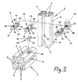
- the profile bars 1 and 2 are generally identical and have an essentially rectangular or square outline, wherein at least axially parallel or centrally undercut longitudinal grooves 3 and 4 are formed in the profile bars 1 and 2.
- the longitudinal grooves 3 and 4 of the profile bars 1 and 2 have narrowed opening slots 7 and 8, through which the connecting means for bracing the profile bars 1 and 2 are accessible to one another.
- the connecting means include a tension member 9, 10 or 11, which can be equipped with different shaped heads 12, 13 or 14.
- These tension members 9, 10 or 11 can be used alternatively, the molding heads 12, 13 or 14 are each designed so that they can be inserted into the respective longitudinal groove 4 under a positive connection acting transversely to the longitudinal axis of the second profile bar 2.
- the tension member 9 has a shaped head 12 with flats 25 on both sides whose spacing is smaller than the width of the opening slot 8 of the longitudinal groove 4 of the second profile bar 2.
- the flats 25 are arranged so that the upright alignment head 12 of the tension member 9 into the longitudinal groove 4th of the second profile rod 1 can be inserted and secured in it after turning 90 degrees.
- the shaped head 12 of the tension member 9 is integrally connected to a shaped body 15 by means of a neck 28, the length and diameter of the neck 28 being adapted to the passage through the opening slot 8 of the relevant longitudinal groove 4 of the second profile bar 2.
- the elongated shaped body 15 has on its inside a shaped groove 16 which is V-shaped and thus has a cross section in the shape of a triangle.
- the molded body 15 On the outside of the molded groove 16, the molded body 15 has a longitudinal web 17, with which the molded body 15 has an overall circumferential contour which, with the exception of the region of the molded groove 16, corresponds to the hollow contour of the longitudinal grooves 3 of the first profile bar 1.
- the molded body 15 of the tension member 9 can be inserted from the end face of the profile bar 1 into the relevant longitudinal groove 3 in a manner such that it cannot rotate.
- a threaded hole 18 with a pressure screw 19 penetrates the shaped body 15, the arrangement and function of which is explained below with reference to FIG. 3.
- the tension member 10 corresponds to the tension member 9 with the exception of the design of the molding head 13, which here has a mushroom shape, that is to say it is not provided with the flats 25 of the molding head 12 of the tension member 9.
- the tension member 10 with the molding head 13 must therefore be inserted into the relevant longitudinal groove 4 of the second profile bar 2 from the front side.
- the tension member 11 also corresponds to the tension members 9 or 10 insofar as it relates to the molded body 15.
- the detachable molding head 14 can have a shape that fills the associated longitudinal groove 4 of the second profile bar 2, it must then be inserted from the end face, and on the other hand it can also be designed as a fitting through the opening slot 8 of the relevant longitudinal groove 4.
- the connecting means include an anchor part 20, which consists of an elongated, prismatic body 21, the cross section of which represents the positive contour of the shaped groove 16 on the tension member 9, 10 or 11.
- the body 21 of the anchor part 20 On one end face, the body 21 of the anchor part 20 has an inclined support surface 22 which, in the installed position, faces away from the second profile bar 2.
- the body 21 of the anchor part 20 has a pin 23 projecting perpendicular to its longitudinal extension, which corresponds to a bore 24 which is located at the bottom of the longitudinal groove 3 of the profiled rod 1, which in the connecting position is in one plane with that on the support side of the second Profile bar 2 arranged longitudinal groove 4 is located.
- the bore 24 is so close to the end face of the first profile bar 1 that the body 21 of the anchor part 20 protrudes with the pin 23 inserted therein on the face side above the profile bar 1 and protrudes into the opening slot 8 of the opposite longitudinal groove 4 of the second profile bar 2.
- the width of the body 21 of the anchor part 20 is therefore dimensioned such that the body 21 fits exactly into the opening width of the opening slot 8 of the longitudinal groove 4 of the second profile bar 2.
- FIG. 3 shows further details on this, with its form head 13 in a form-fitting manner transversely to the axial direction of the second Profile bar 2 secured tension member 10 sits in the assembled arrangement in the relevant longitudinal groove 3 of the first profile bar 1 and covers the anchor part 20 there.
- the pressure screw 19 in the threaded bore 18 of the tension member 10 is tightened against the support surface 22 of the anchor part 21, and this support surface 22 is Appropriately arranged for the purpose of force in a plane perpendicular to the axis of the pressure screw 19.
- an additional force component which lies transversely to the longitudinal direction of the first profile bar 1
- the longitudinal axis of the pressure screw 19 is inclined at an angle of 45 degrees with respect to the longitudinal axis of the first profile bar 1, that in the tensioned state the tension member 10 is under tension and accordingly the end face of the first profile bar 1 is pressed against the long side of the second profile bar 2 becomes. This is accomplished by the force component in the pressure screw 19 acting parallel to the axial direction of the first profile bar 1, while the force component acting perpendicularly thereto presses the body 21 of the anchor part 20 against the bottom of the longitudinal groove 3 of the first profile bar 1.
Landscapes
- Engineering & Computer Science (AREA)
- Architecture (AREA)
- General Engineering & Computer Science (AREA)
- Physics & Mathematics (AREA)
- Electromagnetism (AREA)
- Civil Engineering (AREA)
- Structural Engineering (AREA)
- Mechanical Engineering (AREA)
- Mutual Connection Of Rods And Tubes (AREA)
- Reinforcement Elements For Buildings (AREA)
- Joining Of Building Structures In Genera (AREA)
Claims (13)
- Assemblage transversal de barres profilées (1, 2) pourvues de rainures longitudinales (3, 4) contre-dépouillées, exécutées notamment en métal léger, le côté frontal de la première barre profilée (1) étant abouté sur un côté longitudinal de la deuxième barre profilée (2) et des membres tendus (9, 10, 11) étant insérés dans les rainures longitudinales (3, 4) des barres profilées (1, 2), lesquelles rainures longitudinales (3, 4) affleurent sur un plan, alors que les membres tendus (9, 10, 11) s'engagent positivement, d'une part, à l'aide d'une tête (12, 13, 14), dans la rainure longitudinale (4) de la deuxième barre profilée (2) et, d'autre part, s'appuient sur une pièce d'ancrage (20), en saillie dans la rainure longitudinale (3) de la première barre profilée (1), à l'aide d'une vis de pression (19) oblique par rapport à l'axe longitudinal de la première barre profilée (1), qui agit dans le sens longitudinal de cette barre profilée (1) avec un composant de force,
caractérisé en ce que
la pièce d'ancrage (20) comprend un corps (21) à surface d'appui oblique, à peu près perpendiculaire à l'axe de la vis de pression, du côté frontal détourné de la deuxième barre profilée (2), lequel est assis sur le fond de la rainure longitudinale (3) de la première barre profilée (1) et s'engage dans une forure (24) du fond de la rainure, à l'aide d'un tenon (23), et que le membre tendu (9, 10, 11) présente une surface intérieure (16) adaptée aux contours du corps (21) de la pièce d'ancrage (20), lequel vient s'y emboîter, la prise d'appui étant réciproque. - Assemblage transversal selon la revendication 1,
caractérisé en ce que
la section transversale du membre tendu (9, 10, 11) présente un contour enveloppant, qui est adapté géométriquement à la section transversale de la rainure longitudinale de la première barre profilée (1). - Assemblage transversal selon la revendication 2,
caractérisé en ce que
le membre tendu (9, 10, 11) est pourvu, du côté opposé à la surface intérieure (16), d'une barre longitudinale (17) en saillie, qui prend dans la fente d'ouverture (7) de la rainure longitudinale (3) de la première barre profilée (1) et dont la largeur est adaptée à la largeur de cette ouverture. - Assemblage transversal selon l'une des revendications 1 à 3,
caractérisé en ce que
la tête (12, 13) est formée d'une pièce à partir du membre tendu (9, 10), avec lequel elle est reliée par un col (28), dont la section transversale est adaptée à la largeur intérieure de la fente d'ouverture (8) de la rainure longitudinale (4) de la deuxième barre profilée (2). - Assemblage transversal selon la revendication 4,
caractérisé en ce que
la tête (12) du membre tendu (9) présente des aplatissements bilatéraux (25), dont l'intervalle est inférieur à la largeur d'ouverture de la fente (8) de la rainure longitudinale (4) de la deuxième barre profilée (2). - Assemblage transversal selon l'une des revendications 1 à 3,
caractérisé en ce que
le membre tendu (11) et la tête (14) sont reliés ensemble, de façon amovible, à l'aide de membres à engagement positif. - Assemblage transversal selon la revendication 6,
caractérisé en ce que
le membre tendu (11) est pourvu, frontalement, d'un nez fileté (26) et la tête (14) d'une forure filetée. - Assemblage transversal selon l'une des revendications 1 à 7,
caractérisé en ce que
le corps (21) de la pièce d'ancrage (20) fait saillie dans la fente d'ouverture (8) de la rainure longitudinale (4) de la deuxième barre profilée (2) et possède une largeur adaptée à la largeur d'ouverture de la fente (8) de la rainure longitudinale (4) de la deuxième barre profilée (2). - Assemblage transversal selon l'une des revendications 1 à 8,
caractérisé en ce que
le corps (21) de la pièce d'ancrage (20) est de forme allongée et que la section transversale de la face intérieure (16) du membre tendu (9, 10, 11) présente un contour négatif correspondant. - Assemblage transversal selon la revendication 9,
caractérisé en ce que
la face intérieure (16) du corps (21) de la pièce d'ancrage (20) est conçue sous forme de rainure moulée. - Assemblage transversal selon les revendications 9 et 10,
caractérisé en ce que
le corps (21) de la pièce d'ancrage (20) est de forme prismatique et possède une section transversale triangulaire. - Assemblage transversal selon la revendication 10 ou 11,
caractérisé en ce que
la rainure (16) s'étend sur la longueur totale du membre tendu (9, 10, 11) et est ouverte sur les parties frontales de celui-ci. - Assemblage transversal selon l'une des revendication 1 à 12,
caractérisé en ce que
la vis de pression (19) du membre tendu (9, 10, 11) est disposée sous un angle de 30 à 60 degrés par rapport à l'axe longitudinal de la première barre profilée (1) et que la surface d'appui (22) de la pièce d'ancrage (20) est perpendiculaire à l'axe de la vis de pression (19).
Applications Claiming Priority (2)
| Application Number | Priority Date | Filing Date | Title |
|---|---|---|---|
| DE4135674A DE4135674C2 (de) | 1991-10-30 | 1991-10-30 | Verbindung für Profilstäbe mit hinterschnittenen Längsnuten |
| DE4135674 | 1991-10-30 |
Publications (2)
| Publication Number | Publication Date |
|---|---|
| EP0539687A1 EP0539687A1 (fr) | 1993-05-05 |
| EP0539687B1 true EP0539687B1 (fr) | 1994-10-12 |
Family
ID=6443685
Family Applications (1)
| Application Number | Title | Priority Date | Filing Date |
|---|---|---|---|
| EP92114603A Expired - Lifetime EP0539687B1 (fr) | 1991-10-30 | 1992-08-27 | Joint perpendiculaire pour des profilés avec des rainures longitudinales |
Country Status (3)
| Country | Link |
|---|---|
| EP (1) | EP0539687B1 (fr) |
| AT (1) | ATE112823T1 (fr) |
| DE (2) | DE4135674C2 (fr) |
Cited By (2)
| Publication number | Priority date | Publication date | Assignee | Title |
|---|---|---|---|---|
| DE10318642A1 (de) * | 2003-04-24 | 2004-11-18 | Maytec Aluminium Systemtechnik Gmbh | Verdrehsicherung |
| CN109798289A (zh) * | 2019-03-12 | 2019-05-24 | 江苏能建机电实业集团有限公司 | 一种铝型材组合体及其组装方法 |
Families Citing this family (12)
| Publication number | Priority date | Publication date | Assignee | Title |
|---|---|---|---|---|
| DE4326642C2 (de) * | 1993-08-09 | 1995-11-16 | Festo Kg | Verbindungseinrichtung für Profilteile |
| FR2717870B1 (fr) * | 1994-03-22 | 1996-05-10 | Ermo Sa | Système de fixation pour structures en barres profilées. |
| DE9413839U1 (de) * | 1994-08-26 | 1995-03-09 | Erbsloeh Julius & August | Verbindungselement für die Bildung einer etwa T-förmigen Verbindung von Profilstäben, insbesondere aus Leichtmetall |
| FR2735558B1 (fr) * | 1995-06-16 | 1997-09-05 | Gautreau Andre | Dispositif d'assemblage pour barres profilees |
| DE19641500C2 (de) * | 1996-10-09 | 2001-10-25 | Siegfried Aichner | Vorrichtung zum lösbaren Verbinden von Profilstäben |
| DE19745685C1 (de) * | 1997-10-16 | 1999-07-29 | Felix Leeb | Schraubverbindungen von Rahmenprofilen wie Stoß- und Dauerverbindungen |
| DE19806922C1 (de) * | 1998-02-19 | 1999-05-27 | Hautec Systemelemente Gmbh | Querverbinder für mit hinterschnittenen Längsnuten versehene stranggezogene Hohlprofilstäbe |
| DE19855928A1 (de) * | 1998-12-04 | 2000-06-08 | Wolfgang Rixen | Verbindung zweier Profilstäbe |
| GB0106653D0 (en) * | 2001-03-17 | 2001-05-09 | R A Whiting Design Ltd | Roof assembly |
| PL397842A1 (pl) | 2012-01-19 | 2013-07-22 | Bogdan Malecki | Sposób montazu konstrukcji o konfiguracji plaszczyznowej i/lub przestrzennej, zespól polaczeniowy do montazu konstrukcji o konfiguracji plaszczyznowej i/lub przestrzennej oraz element polaczeniowy do montazu konstrukcji o konfiguracji plaszczyznowej i/lub przestrzennej |
| US9328752B2 (en) * | 2012-02-27 | 2016-05-03 | James Hardie Technology Limited | Rail clip for forming door and window assemblies |
| CN108035951A (zh) * | 2018-01-18 | 2018-05-15 | 大连美德乐工业组装技术有限公司 | 带有独特的内藏式锁紧机构的型材连接件 |
Family Cites Families (5)
| Publication number | Priority date | Publication date | Assignee | Title |
|---|---|---|---|---|
| GB1003207A (en) * | 1963-06-25 | 1965-09-02 | Sankey Sheldon Ltd | Improvements relating to framework structures |
| DE1919678A1 (de) * | 1969-04-18 | 1970-11-05 | Bayer Ag | Alpha-Methylol-benzoin-sulfonsaeureester |
| DE6923289U (de) * | 1969-06-11 | 1969-11-08 | Maiworm & Co Fa | Eckverbindung an rohrfussgestellen |
| DE2812502A1 (de) * | 1978-03-22 | 1979-09-27 | Kluge Dr Heinz Nachf | Vorrichtung zum verbinden von zwei profilstaeben |
| DE3339425A1 (de) * | 1983-10-29 | 1985-05-09 | Item Industrietechnik und Maschinenbau GmbH, 5650 Solingen | Vorrichtung zum stirnseitigen verbinden eines strangprofils mit einem wenigstens an der verbindungsstelle durchlaufenden strangprofil |
-
1991
- 1991-10-30 DE DE4135674A patent/DE4135674C2/de not_active Expired - Lifetime
-
1992
- 1992-08-27 AT AT92114603T patent/ATE112823T1/de active
- 1992-08-27 DE DE59200625T patent/DE59200625D1/de not_active Expired - Lifetime
- 1992-08-27 EP EP92114603A patent/EP0539687B1/fr not_active Expired - Lifetime
Cited By (3)
| Publication number | Priority date | Publication date | Assignee | Title |
|---|---|---|---|---|
| DE10318642A1 (de) * | 2003-04-24 | 2004-11-18 | Maytec Aluminium Systemtechnik Gmbh | Verdrehsicherung |
| DE10318642B4 (de) * | 2003-04-24 | 2005-08-18 | Maytec Aluminium Systemtechnik Gmbh | Verdrehsicherung |
| CN109798289A (zh) * | 2019-03-12 | 2019-05-24 | 江苏能建机电实业集团有限公司 | 一种铝型材组合体及其组装方法 |
Also Published As
| Publication number | Publication date |
|---|---|
| ATE112823T1 (de) | 1994-10-15 |
| DE59200625D1 (de) | 1994-11-17 |
| DE4135674C1 (fr) | 1993-04-29 |
| EP0539687A1 (fr) | 1993-05-05 |
| DE4135674C2 (de) | 1997-04-17 |
Similar Documents
| Publication | Publication Date | Title |
|---|---|---|
| DE3204737C1 (de) | Loesbare Verbindung von zwei rechtwinklig zueinander stehenden Platten,vorzugsweise Moebelplatten | |
| EP0506607B1 (fr) | Dispositif de serrage pour joindre deux profilés de façon détachable | |
| EP0539687B1 (fr) | Joint perpendiculaire pour des profilés avec des rainures longitudinales | |
| AT405757B (de) | Verbindungsstück für die lösbare verbindung zweier profilstäbe, vorzugsweise aus leichtmetall | |
| EP0278252A2 (fr) | Profilé d'ancrage | |
| DE4210456A1 (de) | Querverbindung für Profilstäbe mittels Zuggliedern | |
| EP3613912A1 (fr) | Composant modulaire ainsi que pièce apportée permettant de construire des structures tridimensionnelles pour la réception fixe en position de pièces à usiner | |
| DE19641500A1 (de) | Vorrichtung zum lösbaren Verbinden von Profilstäben | |
| DE4024096C2 (fr) | ||
| EP1482187A1 (fr) | Dispositif pour relier des extrémités de barre | |
| DE1755529C3 (de) | Verbindungsglied für Reifenketten | |
| EP3243008B1 (fr) | Raccord de liaison | |
| DE2233615C3 (de) | Kettenschloß | |
| EP0436795B1 (fr) | Fixation d'une poignée de porte au carré | |
| DE3632026C2 (fr) | ||
| EP0511237B1 (fr) | Raccord central, en particulier pour lames metalliques de machines a tisser | |
| EP0641940A2 (fr) | Dispositif de connexion pour pièces profilées | |
| DE102022131891B3 (de) | Bandtasche | |
| DE4039421C2 (fr) | ||
| DE2552983C3 (de) | Von außen herstellbare Verbindung zweier Wand an Wand benachbarter Gehäuse | |
| DE10033163C2 (de) | Verbindungsbeschlag | |
| DE60113020T2 (de) | Klemmhalterung für Stütz- und Verbindungselemente | |
| DE10144982C2 (de) | Befestigungselement | |
| EP0342256B1 (fr) | Butoir avec des trous de centrage | |
| DE4342070C1 (de) | Haltevorrichtung für ein Andrückrollengehänge |
Legal Events
| Date | Code | Title | Description |
|---|---|---|---|
| PUAI | Public reference made under article 153(3) epc to a published international application that has entered the european phase |
Free format text: ORIGINAL CODE: 0009012 |
|
| AK | Designated contracting states |
Kind code of ref document: A1 Designated state(s): AT BE CH DE DK ES FR GB GR IT LI LU MC NL PT SE |
|
| 17P | Request for examination filed |
Effective date: 19930322 |
|
| 17Q | First examination report despatched |
Effective date: 19940222 |
|
| GRAA | (expected) grant |
Free format text: ORIGINAL CODE: 0009210 |
|
| AK | Designated contracting states |
Kind code of ref document: B1 Designated state(s): AT BE CH DE DK ES FR GB GR IT LI LU MC NL PT SE |
|
| PG25 | Lapsed in a contracting state [announced via postgrant information from national office to epo] |
Ref country code: IT Free format text: LAPSE BECAUSE OF FAILURE TO SUBMIT A TRANSLATION OF THE DESCRIPTION OR TO PAY THE FEE WITHIN THE PRE;WARNING: LAPSES OF ITALIAN PATENTS WITH EFFECTIVE DATE BEFORE 2007 MAY HAVE OCCURRED AT ANY TIME BEFORE 2007. THE CORRECT EFFECTIVE DATE MAY BE DIFFERENT FROM THE ONE RECORDED.SCRIBED TIME-LIMIT Effective date: 19941012 Ref country code: MC Free format text: LAPSE BECAUSE OF NON-PAYMENT OF DUE FEES Effective date: 19941012 Ref country code: DK Effective date: 19941012 Ref country code: BE Effective date: 19941012 Ref country code: NL Effective date: 19941012 Ref country code: ES Free format text: THE PATENT HAS BEEN ANNULLED BY A DECISION OF A NATIONAL AUTHORITY Effective date: 19941012 Ref country code: GR Free format text: LAPSE BECAUSE OF FAILURE TO SUBMIT A TRANSLATION OF THE DESCRIPTION OR TO PAY THE FEE WITHIN THE PRESCRIBED TIME-LIMIT Effective date: 19941012 Ref country code: FR Effective date: 19941012 |
|
| REF | Corresponds to: |
Ref document number: 112823 Country of ref document: AT Date of ref document: 19941015 Kind code of ref document: T |
|
| REF | Corresponds to: |
Ref document number: 59200625 Country of ref document: DE Date of ref document: 19941117 |
|
| GBT | Gb: translation of ep patent filed (gb section 77(6)(a)/1977) |
Effective date: 19941101 |
|
| PG25 | Lapsed in a contracting state [announced via postgrant information from national office to epo] |
Ref country code: SE Effective date: 19950112 Ref country code: PT Effective date: 19950112 |
|
| EN | Fr: translation not filed | ||
| NLV1 | Nl: lapsed or annulled due to failure to fulfill the requirements of art. 29p and 29m of the patents act | ||
| PLBI | Opposition filed |
Free format text: ORIGINAL CODE: 0009260 |
|
| 26 | Opposition filed |
Opponent name: SCHUECO INTERNATIONAL KG Effective date: 19950627 |
|
| PG25 | Lapsed in a contracting state [announced via postgrant information from national office to epo] |
Ref country code: LU Free format text: LAPSE BECAUSE OF NON-PAYMENT OF DUE FEES Effective date: 19950831 |
|
| PLBF | Reply of patent proprietor to notice(s) of opposition |
Free format text: ORIGINAL CODE: EPIDOS OBSO |
|
| PLBF | Reply of patent proprietor to notice(s) of opposition |
Free format text: ORIGINAL CODE: EPIDOS OBSO |
|
| PLBF | Reply of patent proprietor to notice(s) of opposition |
Free format text: ORIGINAL CODE: EPIDOS OBSO |
|
| PLBF | Reply of patent proprietor to notice(s) of opposition |
Free format text: ORIGINAL CODE: EPIDOS OBSO |
|
| PLBO | Opposition rejected |
Free format text: ORIGINAL CODE: EPIDOS REJO |
|
| PLBN | Opposition rejected |
Free format text: ORIGINAL CODE: 0009273 |
|
| STAA | Information on the status of an ep patent application or granted ep patent |
Free format text: STATUS: OPPOSITION REJECTED |
|
| 27O | Opposition rejected |
Effective date: 19960721 |
|
| REG | Reference to a national code |
Ref country code: GB Ref legal event code: IF02 |
|
| PGFP | Annual fee paid to national office [announced via postgrant information from national office to epo] |
Ref country code: CH Payment date: 20110620 Year of fee payment: 20 |
|
| PGFP | Annual fee paid to national office [announced via postgrant information from national office to epo] |
Ref country code: DE Payment date: 20110810 Year of fee payment: 20 Ref country code: AT Payment date: 20110624 Year of fee payment: 20 Ref country code: GB Payment date: 20110803 Year of fee payment: 20 |
|
| REG | Reference to a national code |
Ref country code: DE Ref legal event code: R071 Ref document number: 59200625 Country of ref document: DE |
|
| REG | Reference to a national code |
Ref country code: DE Ref legal event code: R071 Ref document number: 59200625 Country of ref document: DE |
|
| REG | Reference to a national code |
Ref country code: CH Ref legal event code: PL |
|
| REG | Reference to a national code |
Ref country code: GB Ref legal event code: PE20 Expiry date: 20120826 |
|
| REG | Reference to a national code |
Ref country code: AT Ref legal event code: MK07 Ref document number: 112823 Country of ref document: AT Kind code of ref document: T Effective date: 20120827 |
|
| PG25 | Lapsed in a contracting state [announced via postgrant information from national office to epo] |
Ref country code: GB Free format text: LAPSE BECAUSE OF EXPIRATION OF PROTECTION Effective date: 20120826 Ref country code: DE Free format text: LAPSE BECAUSE OF EXPIRATION OF PROTECTION Effective date: 20120828 |