EP0538608B1 - Vorrichtung zur Tilgung von Torsionsschwingungen - Google Patents
Vorrichtung zur Tilgung von Torsionsschwingungen Download PDFInfo
- Publication number
- EP0538608B1 EP0538608B1 EP92115243A EP92115243A EP0538608B1 EP 0538608 B1 EP0538608 B1 EP 0538608B1 EP 92115243 A EP92115243 A EP 92115243A EP 92115243 A EP92115243 A EP 92115243A EP 0538608 B1 EP0538608 B1 EP 0538608B1
- Authority
- EP
- European Patent Office
- Prior art keywords
- damper
- frame
- way
- bearings
- vehicle
- Prior art date
- Legal status (The legal status is an assumption and is not a legal conclusion. Google has not performed a legal analysis and makes no representation as to the accuracy of the status listed.)
- Expired - Lifetime
Links
Images


Classifications
-
- B—PERFORMING OPERATIONS; TRANSPORTING
- B60—VEHICLES IN GENERAL
- B60J—WINDOWS, WINDSCREENS, NON-FIXED ROOFS, DOORS, OR SIMILAR DEVICES FOR VEHICLES; REMOVABLE EXTERNAL PROTECTIVE COVERINGS SPECIALLY ADAPTED FOR VEHICLES
- B60J1/00—Windows; Windscreens; Accessories therefor
- B60J1/20—Accessories, e.g. wind deflectors, blinds
-
- B—PERFORMING OPERATIONS; TRANSPORTING
- B62—LAND VEHICLES FOR TRAVELLING OTHERWISE THAN ON RAILS
- B62D—MOTOR VEHICLES; TRAILERS
- B62D37/00—Stabilising vehicle bodies without controlling suspension arrangements
- B62D37/04—Stabilising vehicle bodies without controlling suspension arrangements by means of movable masses
-
- F—MECHANICAL ENGINEERING; LIGHTING; HEATING; WEAPONS; BLASTING
- F16—ENGINEERING ELEMENTS AND UNITS; GENERAL MEASURES FOR PRODUCING AND MAINTAINING EFFECTIVE FUNCTIONING OF MACHINES OR INSTALLATIONS; THERMAL INSULATION IN GENERAL
- F16F—SPRINGS; SHOCK-ABSORBERS; MEANS FOR DAMPING VIBRATION
- F16F7/00—Vibration-dampers; Shock-absorbers
- F16F7/10—Vibration-dampers; Shock-absorbers using inertia effect
- F16F7/104—Vibration-dampers; Shock-absorbers using inertia effect the inertia member being resiliently mounted
Definitions
- the invention relates to a Device for the extinction of torsional vibrations on the body of a cabriolet vehicle via an absorber consisting of a mass body held by means of elastic bearings, the absorber being held elastically on a frame of a windshield via drawer bearings and being relatively freely oscillating at a distance from the frame in transverse directions of the vehicle and the damper has a frequency equal to the torsional natural frequency of the vehicle in the area of the frame and the bearings have a shear stiffness due to their geometry.
- vibration absorbers for the various areas of application in vehicle construction, such as a drive shaft (DE-OS 36 32 418) and a drive unit (DE-PS 31 25 830) known. These absorbers are held in elastic bushings which, due to the space available, can occupy a space corresponding to optimal vibration damping.
- the object of the invention is to provide a vibration damper in a convertible vehicle, which ensures an optimally coordinated eradication of vibrations to the torsional natural frequencies of the vehicle.
- leaf springs are used which, in interaction with a drawer bearing arranged in the center of the absorber mass, ensure a targeted transverse displacement of the mass body and the leaf springs deflect into Prevent vertical and longitudinal directions of the vehicle, which ensures targeted guidance of the absorber mass.
- the main advantages achieved with the invention are that the vibrations on the frame of the windshield can be reduced by the absorber to the extent that e.g. an unobstructed rear view is made possible by the mirror attached to the windshield or the frame.
- the usual vibration behavior, especially in the area of fittings with a steering wheel, is significantly improved.
- the damper is attached to a frame element that can be connected to the upper window frame of the vehicle. This takes place via at least one central drawer bearing and the leaf spring elements arranged at the free ends of the absorber mass.
- the absorber mass is held over the leaf spring elements so that only a transverse movement can take place and movement in other directions is largely excluded.
- the one or more drawer bearings are (are) exposed in a recess in the absorber mass, so that an unimpeded transverse movement of the absorber mass can take place.
- the guidance in this direction takes place via the leaf spring elements attached at the ends, which are accordingly stiff in the vertical and longitudinal direction and soft in the transverse direction.
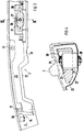
- a known device 1 for the extinction of torsional vibrations according to DE 40 30 990 A1 comprises, according to FIGS. 1 and 2, an absorber 2 on the upper window frame 3 or on the roof frame of a windshield 4, which is attached to elastic bearings 5 and 6 in the direction of the arrows 7 and 8 is arranged approximately horizontally swinging movable.
- the absorber 2 consists of a metallic material with the largest possible specific gravity, such as Steel, lead or the like material, and is end, i.e. held at its free ends 9 and 10 in these elastic bearings 5 and 6.
- the absorber 2 can also be supported in an elastically movable manner in at least one central drawer bearing 21 on a frame element 22 in transverse directions 7, 8.
- the free ends of the absorber mass 23 are each connected to a leaf spring element 24 which guides the absorber mass 23 in transverse directions 7, 8.
- the leaf spring elements 24 are made relatively rigid in the vertical directions 25 and longitudinal directions 26 and, on the other hand, are softer in the transverse directions 7 and 8.
- the drawer bearing 21 is arranged in a recess 27 in the absorber mass 23 and is fastened at one end 28 to the frame element 22 and is connected at another end 29 to the absorber mass 23 via a holder 30.
- two or more bearings can also hold the damper mass 23 in transverse directions 7 and 8.
- the bearing 21, e.g. designed as a round bearing, is dimensioned in such a way that it has an identifier that largely does not permit movement of the absorber mass 23 in the vertical and longitudinal directions, but allows an elastic movement in the transverse directions correspondingly matched to the torsional natural frequency of the body.
- the end leaf spring elements 24 have a defined height and thickness, which ensures precise guidance of the absorber mass 23 in transverse directions without deflection in the vertical and longitudinal directions.
- the frame element 22 designed as a half-shell, accommodates the damper 2 and can be connected as a structural unit to the disk frame 3, which is likewise designed as a half-shell, by means of screws.
- the corresponding bores 31 for the passage of the screws are shown in more detail in FIG. 3.
Landscapes
- Engineering & Computer Science (AREA)
- Mechanical Engineering (AREA)
- General Engineering & Computer Science (AREA)
- Chemical & Material Sciences (AREA)
- Combustion & Propulsion (AREA)
- Transportation (AREA)
- Vibration Prevention Devices (AREA)
- Body Structure For Vehicles (AREA)
- Springs (AREA)
Description
- Die Erfindung bezieht sich auf eine
Vorrichtung zur Tilgung von aufbauseitigen Torsionsschwingungen an einem Cabriolet-Fahrzeug über einen aus einem mittels elastischer Lager gehaltenen Massekörper bestehenden Tilger, wobei der Tilger an einem Rahmen einer Windschutzscheibe über Schublager elastisch gehalten und mit Abstand zum Rahmen in Querrichtungen des Fahrzeugs relativ frei schwingend angeordnet ist und der Tilger eine der Torsionseigenfrequenz des Fahrzeugs im Bereich des Rahmens gleiche Frequenz aufweist und die Lager eine durch ihre Geometrie bedingte Schubsteifigkeit aufweisen. - Bei Fahrzeugen in Cabriolet-Bauweise treten aufgrund der Struktur, die gegenüber Coupé-Fahrzeugen eine geringere Torsionssteifigkeit aufweisen, die insbesondere im Bereich der Windschutzscheibe derartige Vibrationen bzw. Schwingungsausschläge verursachen, daß z.B. der an der Windschutzscheibe befestigte Rückblickspiegel solche Schwingungen ausführt, daß ein Rückblick erschwert wird.
- Es sind Schwingungstilger für die verschiedenen Anwendungsbereiche im Fahrzeugbau, wie z.B. eine Antriebswelle (DE-OS 36 32 418) und eine Antriebseinheit (DE-PS 31 25 830) bekannt. Diese Tilger sind in elastischen Buchsen gehalten, welche aufgrund der Platzverhältnisse einen zur optimalen Schwingungsdämpfung entsprechenden Raum einnehmen können.
- Aufgabe der Erfindung ist es, einen Schwingungstilger in einem Cabriolet-Fahrzeug zu schaffen, der eine optimal abgestimmte Tilgung von Schwingungen auf die Torsionseigenfrequenzen des Fahrzeuges gewährleistet.
- Diese Aufgabe wird erfindungsgemäß durch die Merkmale des Anspruchs 1 gelöst. Weitere vorteilhafte Merkmale beinhalten die Unteransprüche.
- In dem internen stand der Technik DE-40 30 990 A1 ist bereits ein Schwingungstilger im Scheibenrahmen eines Cabriolet-Fahrzeugs beschrieben, der endseitig in elastischen Schublagern gehalten wird und über diese im Rahmen abgestützt ist. Diese Lager sind in Querrichtung des Fahrzeugs sehr viel weicher ausgelegt als in Hoch- und Längsrichtungen.
- Nach der Erfindung wird gegenüber der Hauptanmeldung P 40 30 990.8, bei der endseitig angeordnete elastische Gummilager als Schublager Verwendung finden, spezielle Blattfedern verwendet, die im Zusammenspiel mit einem mittig der Tilgermasse angeordneten Schublager eine gezielte Querverschiebung des Massenkörpers gewährleisten und wobei die Blattfedern ein Auslenken in Hoch- und Längsrichtungen des Fahrzeugs unterbinden, wodurch eine gezielte Führung der Tilgermasse gewährleistet ist.
- Die mit der Erfindung hauptsächlich erzielten Vorteile bestehen darin, daß die Schwingungen am Rahmen der Windschutzscheibe über den Tilger soweit abgebaut werden können, daß z.B. ein ungehinderter Rückblick durch den an der Windschutzscheibe oder am Rahmen befestigten Spiegel ermöglicht wird. Darüber hinaus wird auch das übliche Schwingungsverhalten, insbesondere im Armaturenbereich mit Lenkrad, deutlich verbessert.
- Der Tilger ist an einem Rahmenelement, das mit dem oberen Scheibenrahmen des Fahrzeugs verbindbar ist, befestigt. Dies erfolgt über mindestens ein mittiges Schublager und den an den freien Enden der Tilgermasse angeordneten Blattfederelementen. Die Tilgermasse ist über die Blattfederelemente so gehalten, daß nur eine Querbewegung erfolgen kann und eine Bewegung in anderen Richtungen weitestgehend ausgeschlossen wird.
- Das oder die Schublager ist (sind) in einer Ausnehmung der Tilgermasse freiliegend angeordnet, so daß eine unbehinderte Querbewegung der Tilgermasse erfolgen kann. Die Führung in dieser Richtung erfolgt über die endseitig angebrachten Blattfederelemente, die hierzu dementsprechend in Hoch- und Längsrichtung steif sowie in Querrichtung weich dimensioniert sind.
- Wenn zwei nebeneinander im Abstand angeordnete Schublager in der Tilgermasse Verwendung finden, ist eine breitere Lagerbasis für die Tilgermasse in Querrichtung gewährleistet, als bei nur einem Schublager.
- Ein Ausführungsbeispiel der Erfindung ist in der Zeichnung dargestellt und wird im folgenden näher beschrieben.
Es zeigen - Fig. 1
- eine schematische Darstellung eines Einbauortes des Schwingungstilgers im Scheibenrahmen,
- Fig. 2
- eine vergrößerte Darstellung Z aus Fig. 1 des Schwingungstilgers in dem oberen Scheibenrahmen,
- Fig. 3
- eine Draufsicht auf einen Tilger mit endseitigen Blattfederelementen und einem mittigen Schublager,
- Fig. 4
- einen Schnitt nach der Linie II-II der Fig. 1,
- Fig. 5
- einen Schnitt nach der Linie III-III der Fig. 2, und
- Fig. 6
- eine Sicht in Richtung X der Fig. 1.
- Eine bekannte Vorrichtung 1 zur Tilgung von Torsionsschwingungen nach der DE- 40 30 990 A1 umfasst gemäß der Fig. 1 und 2 einen Tilger 2 am oberen Scheibenrahmen 3 bzw. am Dachrahmen einer Windschutzscheibe 4, welche an elastischen Lagern 5 und 6 in Pfeilrichtungen 7 und 8 annähernd horizontal schwingend bewegbar angeordnet ist. Der Tilger 2 besteht aus einem metallischen Werkstoff mit einer möglichst großen spezifischen Wichte, wie z.B. Stahl, Blei oder dergleichen Werkstoff, und ist endseitig, d.h. an seinen freien Enden 9 und 10 in diesen elastischen Lagern 5 und 6 gehalten. Der Tilger 2 kann nach einer Weiterbildung auch über mindestens ein mittiges Schublager 21 an einem Rahmenelement 22 in Querrichtungen 7, 8 elastisch bewegbar abgestützt sein. Die freien Enden der Tilgermasse 23 sind jeweils mit einem Blattfederelement 24 verbunden, das die Tilgermasse 23 in Querrichtungen 7, 8 führt. Hierzu sind die Blattfederelemente 24 in Hochrichtungen 25 und Längsrichtungen 26 relativ steif ausgeführt und in den Querrichtungen 7 und 8 dagegen weicher.
- Das Schublager 21 ist in einer Ausnehmung 27 der Tilgermasse 23 angeordnet und mit einem Ende 28 am Rahmenelement 22 befestigt und mit einemam anderen Ende 29 über einen Halter 30 mit der Tilgermasse 23 verbunden. Statt des einen Lagers 21 können auch zwei oder mehrere Lager die Tilgermasse 23 in Querrichtungen 7 und 8 bewegbar halten.
- Das Lager 21, z.B. als Rundlager ausgeführt, ist in der Weise dimensioniert, daß es eine Kennung aufweist, die in Hoch- und Längsrichtungen weitestgehend keine Bewegung der Tilgermasse 23 zulässt, aber in Querrichtungen entsprechend abgestimmt auf die Torsionseigenfrequenz der Karosserie eine elastische Bewegung ermöglicht. Die endseitigen Blattfederelemente 24 weisen eine definierte Höhe und Dicke auf, die eine exakte Führung der Tilgermasse 23 in Querrichtungen ohne Auslenkung in Hoch- und Längsrichtungen gewährleistet.
- Das Rahmenelement 22, als Halbschale ausgeführt, nimmt den Tilger 2 auf und ist als Baueinheit mit dem ebenfalls als Halbschale ausgebildeten Scheibenrahmen 3 über Schrauben verbindbar. Die entsprechenden Bohrungen 31 zur Durchführung der Schrauben sind in Fig. 3 näher dargestellt. Nach Befestigung des Rahmenelements 2 am Scheibenrahmen 3 bildet der Rahmen eine geschlossene Einheit mit innenliegendem Tilger 2.
Claims (4)
- Vorrichtung zur Tilgung von aufbauseitigen Torsionsschwingungen an einem Cabriolet-Fahrzeug über einen aus einem mittels elastischer Lager gehaltenen Massekörper bestehenden Tilger, wobei der Tilger an einem Rahmen einer Windschutzscheibe über Schublager elastisch gehalten und mit Abstand zum Rahmen in Querrichtungen des Fahrzeugs relativ frei schwingend angeordnet ist und der Tilger eine der Torsionseigenfrequenz des Fahrzeugs im Bereich des Rahmens gleiche Frequenz aufweist und die Lager eine durch ihre Geometrie bedingte Schubsteifigkeit aufweisen, wobei der Tilger (2) über mindestens ein mittiges Schublager (21) zum Rahmenelement (22) hin elastisch abgestützt ist, wobei endseitig der Tilgermasse (23) jeweils ein Blattfederelement (24) angeordnet und, eine Querbewegung der Tilgermasse (23) zulassend, abstützend zum Rahmenelement (22) gelagert ist.
- Vorrichtung nach Anspruch 1, dadurch gekennzeichnet, daß das Blattfederelement (24) in Hoch- und Längsrichtungen (25 und 26) steif, aber in Querrichtungen (7 und 8) des Fahrzeugs weich ausgebildet ist.
- Vorrichtung nach den Ansprüchen 1 oder 2, dadurch gekennzeichnet, daß das Schublager (21) in einer Ausnehmung (27) der Tilgermasse (23) freiliegend angeordnet ist und sich einerseits am Rahmenelement (22) abstützt und andererseits über einen Halter (30) mit der Tilgermasse (23) verbunden ist.
- Vorrichtung nach den Ansprüchen 1, 2 oder 3, dadurch gekennzeichnet, daß das Rahmenelement (22) als Anbauteil mit dem über das Schublager (21) und den Blattfederelementen (24) gehaltenen Tilger (2) ausgebildet und über Schrauben am Scheibenrahmen (3) befestigbar ist.
Applications Claiming Priority (2)
| Application Number | Priority Date | Filing Date | Title |
|---|---|---|---|
| DE4134674 | 1991-10-19 | ||
| DE19914134674 DE4134674C2 (de) | 1990-10-01 | 1991-10-19 | Vorrichtung zur Tilgung von Torsionsschwingungen |
Publications (2)
| Publication Number | Publication Date |
|---|---|
| EP0538608A1 EP0538608A1 (de) | 1993-04-28 |
| EP0538608B1 true EP0538608B1 (de) | 1996-02-28 |
Family
ID=6443063
Family Applications (1)
| Application Number | Title | Priority Date | Filing Date |
|---|---|---|---|
| EP92115243A Expired - Lifetime EP0538608B1 (de) | 1991-10-19 | 1992-09-05 | Vorrichtung zur Tilgung von Torsionsschwingungen |
Country Status (4)
| Country | Link |
|---|---|
| EP (1) | EP0538608B1 (de) |
| JP (1) | JPH05301582A (de) |
| DE (1) | DE59205465D1 (de) |
| ES (1) | ES2084230T3 (de) |
Cited By (1)
| Publication number | Priority date | Publication date | Assignee | Title |
|---|---|---|---|---|
| EP4499426A1 (de) * | 2022-03-29 | 2025-02-05 | Jaguar Land Rover Limited | Zu öffnende dachanordnung |
Families Citing this family (6)
| Publication number | Priority date | Publication date | Assignee | Title |
|---|---|---|---|---|
| DE19532039A1 (de) * | 1995-08-31 | 1997-03-06 | Porsche Ag | Vorrichtung zum Bedämpfen von Karosserieschwingungen |
| JP4222267B2 (ja) * | 2004-07-09 | 2009-02-12 | 日産自動車株式会社 | ルーフパネル制振ブラケット |
| FR2887494B1 (fr) * | 2005-06-22 | 2007-09-21 | Peugeot Citroen Automobiles Sa | Pare-brise de vehicule automobile |
| CN104265827B (zh) * | 2014-09-08 | 2016-08-24 | 金坛市德博密封技术有限公司 | 一种用于发动机安装的三维减震安装座 |
| US10919451B2 (en) | 2017-02-24 | 2021-02-16 | SMR Patents S.à.r.l. | Tuned mass damper in an exterior rearview device |
| US10266120B2 (en) | 2017-02-24 | 2019-04-23 | SMR Patents S.à.r.l. | Tuned mass dampers in mirror base |
Family Cites Families (8)
| Publication number | Priority date | Publication date | Assignee | Title |
|---|---|---|---|---|
| FR1069859A (fr) * | 1952-02-23 | 1954-07-13 | It Autolot S R L Soc | Stabilisateur pour véhicules automobiles |
| AU411207B1 (en) * | 1967-01-19 | 1971-03-09 | Alfred Hall Maxwell | Windscreen shock absorber |
| US3438648A (en) * | 1967-10-16 | 1969-04-15 | Brown Auto Stabilizer Co | Vehicle stabilizer |
| US3614126A (en) * | 1969-08-11 | 1971-10-19 | Norman C Carlson | Stabilizing device for automotive vehicles |
| US3606380A (en) * | 1969-11-24 | 1971-09-20 | James W Lewis | Vehicle stabilizing device |
| JPS5784223A (en) * | 1980-11-13 | 1982-05-26 | Nissan Motor Co Ltd | Vibration absorber of vehicle |
| NL8202673A (nl) * | 1982-07-02 | 1984-02-01 | Nagron Steel & Aluminium | Gastabiliseerd systeem met een eigenfrekwentie. |
| DE59104139D1 (de) * | 1990-10-01 | 1995-02-16 | Porsche Ag | Vorrichtung zur Dämpfung von Torsionsschwingungen. |
-
1992
- 1992-09-05 DE DE59205465T patent/DE59205465D1/de not_active Expired - Fee Related
- 1992-09-05 EP EP92115243A patent/EP0538608B1/de not_active Expired - Lifetime
- 1992-09-05 ES ES92115243T patent/ES2084230T3/es not_active Expired - Lifetime
- 1992-10-15 JP JP4277522A patent/JPH05301582A/ja not_active Withdrawn
Cited By (1)
| Publication number | Priority date | Publication date | Assignee | Title |
|---|---|---|---|---|
| EP4499426A1 (de) * | 2022-03-29 | 2025-02-05 | Jaguar Land Rover Limited | Zu öffnende dachanordnung |
Also Published As
| Publication number | Publication date |
|---|---|
| EP0538608A1 (de) | 1993-04-28 |
| JPH05301582A (ja) | 1993-11-16 |
| ES2084230T3 (es) | 1996-05-01 |
| DE59205465D1 (de) | 1996-04-04 |
Similar Documents
| Publication | Publication Date | Title |
|---|---|---|
| DE710861C (de) | Abfederung, insbesondere fuer Kraftfahrzeuge | |
| EP0615877B1 (de) | Kraftfahrzeug mit einer Antriebsaggregatslagerung | |
| DE19957628B4 (de) | Achsaufhängung für Starrachsen von Fahrzeugen | |
| DE3436869A1 (de) | Hinterradaufhaengungsvorrichtung fuer ein motorrad | |
| DE4134674C2 (de) | Vorrichtung zur Tilgung von Torsionsschwingungen | |
| DE2142523B2 (de) | Radaufhaengung, insbesondere vorderradaufhaengung fuer kraftfahrzeuge | |
| DE3218871C2 (de) | ||
| EP0811512B1 (de) | Radaufhängung für ein Kraftfahrzeug | |
| EP0538608A1 (de) | Vorrichtung zur Tilgung von Torsionsschwingungen | |
| DE2946516A1 (de) | Federaggregat | |
| EP0478936B1 (de) | Vorrichtung zur Dämpfung von Torsionsschwingungen | |
| EP0444016A2 (de) | Triebdrehgestell für elektrische Lokomotiven | |
| DE767646C (de) | Kraftfahrzeug mit unabhaengig voneinander aufgehaengten Raedern | |
| DE3338467A1 (de) | Hinterradaufhaengung | |
| DE1257598B (de) | Vorrichtung zur Tilgung von Schwingungen der ungefederten Massen von Kraftfahrzeugen | |
| DE1780211A1 (de) | Kraftfahrzeug mit einem Aufbau | |
| DE902347C (de) | Motorlagerung fuer Kraftfahrzeuge | |
| DE60302037T2 (de) | Kraftfahrzeug mit schalldämpfendem Rahmen zum Stützen des Motors und der Aufhängung | |
| DE102006011782A1 (de) | Halteelement | |
| EP0121787B1 (de) | Lenkachsenanordnung für einen Radkörper eines Fahrzeugs | |
| DE601579C (de) | Abfederung, insbesondere fuer Kraftfahrzeuge | |
| DE3217171A1 (de) | Schwingungsgedaempfte aufhaengung fuer ein antriebsaggregat eines fahrzeuges in einer aufbaustruktur | |
| DE10253767B4 (de) | Schwingbewegliche Lagerung eines Aggregats an einer Tragstruktur | |
| DE2217182C3 (de) | Abstützung des vorderen Endes von Fahrerhäusern von Lastkraftwagen | |
| DE857899C (de) | Unabhaengige Radaufhaengung eines Radpaares, insbesondere fuer Kraftfahrzeuge |
Legal Events
| Date | Code | Title | Description |
|---|---|---|---|
| PUAI | Public reference made under article 153(3) epc to a published international application that has entered the european phase |
Free format text: ORIGINAL CODE: 0009012 |
|
| AK | Designated contracting states |
Kind code of ref document: A1 Designated state(s): DE ES FR GB IT NL SE |
|
| 17P | Request for examination filed |
Effective date: 19930904 |
|
| 17Q | First examination report despatched |
Effective date: 19950223 |
|
| ITF | It: translation for a ep patent filed | ||
| GRAA | (expected) grant |
Free format text: ORIGINAL CODE: 0009210 |
|
| AK | Designated contracting states |
Kind code of ref document: B1 Designated state(s): DE ES FR GB IT NL SE |
|
| REF | Corresponds to: |
Ref document number: 59205465 Country of ref document: DE Date of ref document: 19960404 |
|
| GBT | Gb: translation of ep patent filed (gb section 77(6)(a)/1977) |
Effective date: 19960315 |
|
| ET | Fr: translation filed | ||
| REG | Reference to a national code |
Ref country code: ES Ref legal event code: FG2A Ref document number: 2084230 Country of ref document: ES Kind code of ref document: T3 |
|
| PGFP | Annual fee paid to national office [announced via postgrant information from national office to epo] |
Ref country code: SE Payment date: 19960916 Year of fee payment: 5 |
|
| PGFP | Annual fee paid to national office [announced via postgrant information from national office to epo] |
Ref country code: NL Payment date: 19960930 Year of fee payment: 5 |
|
| PLBE | No opposition filed within time limit |
Free format text: ORIGINAL CODE: 0009261 |
|
| 26N | No opposition filed | ||
| PG25 | Lapsed in a contracting state [announced via postgrant information from national office to epo] |
Ref country code: SE Free format text: LAPSE BECAUSE OF NON-PAYMENT OF DUE FEES Effective date: 19970906 |
|
| PGFP | Annual fee paid to national office [announced via postgrant information from national office to epo] |
Ref country code: ES Payment date: 19970911 Year of fee payment: 6 |
|
| PG25 | Lapsed in a contracting state [announced via postgrant information from national office to epo] |
Ref country code: NL Free format text: LAPSE BECAUSE OF NON-PAYMENT OF DUE FEES Effective date: 19980401 |
|
| NLV4 | Nl: lapsed or anulled due to non-payment of the annual fee |
Effective date: 19980401 |
|
| EUG | Se: european patent has lapsed |
Ref document number: 92115243.5 |
|
| PGFP | Annual fee paid to national office [announced via postgrant information from national office to epo] |
Ref country code: FR Payment date: 19980828 Year of fee payment: 7 |
|
| PGFP | Annual fee paid to national office [announced via postgrant information from national office to epo] |
Ref country code: GB Payment date: 19980901 Year of fee payment: 7 |
|
| PG25 | Lapsed in a contracting state [announced via postgrant information from national office to epo] |
Ref country code: ES Free format text: LAPSE BECAUSE OF THE APPLICANT RENOUNCES Effective date: 19980907 |
|
| PGFP | Annual fee paid to national office [announced via postgrant information from national office to epo] |
Ref country code: DE Payment date: 19980909 Year of fee payment: 7 |
|
| PG25 | Lapsed in a contracting state [announced via postgrant information from national office to epo] |
Ref country code: GB Free format text: LAPSE BECAUSE OF NON-PAYMENT OF DUE FEES Effective date: 19990905 |
|
| GBPC | Gb: european patent ceased through non-payment of renewal fee |
Effective date: 19990905 |
|
| PG25 | Lapsed in a contracting state [announced via postgrant information from national office to epo] |
Ref country code: FR Free format text: LAPSE BECAUSE OF NON-PAYMENT OF DUE FEES Effective date: 20000531 |
|
| PG25 | Lapsed in a contracting state [announced via postgrant information from national office to epo] |
Ref country code: DE Free format text: LAPSE BECAUSE OF NON-PAYMENT OF DUE FEES Effective date: 20000701 |
|
| REG | Reference to a national code |
Ref country code: FR Ref legal event code: ST |
|
| REG | Reference to a national code |
Ref country code: ES Ref legal event code: FD2A Effective date: 20001102 |
|
| PG25 | Lapsed in a contracting state [announced via postgrant information from national office to epo] |
Ref country code: IT Free format text: LAPSE BECAUSE OF NON-PAYMENT OF DUE FEES Effective date: 20050905 |