EP0538131A1 - Vorrichtung zur Heizung des Fahrgastraums eines Kraftfahrzeuge, insbesondere für einen elektrischen Wagen - Google Patents
Vorrichtung zur Heizung des Fahrgastraums eines Kraftfahrzeuge, insbesondere für einen elektrischen Wagen Download PDFInfo
- Publication number
- EP0538131A1 EP0538131A1 EP92402818A EP92402818A EP0538131A1 EP 0538131 A1 EP0538131 A1 EP 0538131A1 EP 92402818 A EP92402818 A EP 92402818A EP 92402818 A EP92402818 A EP 92402818A EP 0538131 A1 EP0538131 A1 EP 0538131A1
- Authority
- EP
- European Patent Office
- Prior art keywords
- heating
- air
- preheating
- radiator
- switch
- Prior art date
- Legal status (The legal status is an assumption and is not a legal conclusion. Google has not performed a legal analysis and makes no representation as to the accuracy of the status listed.)
- Granted
Links
Images


Classifications
-
- B—PERFORMING OPERATIONS; TRANSPORTING
- B60—VEHICLES IN GENERAL
- B60H—ARRANGEMENTS OF HEATING, COOLING, VENTILATING OR OTHER AIR-TREATING DEVICES SPECIALLY ADAPTED FOR PASSENGER OR GOODS SPACES OF VEHICLES
- B60H1/00—Heating, cooling or ventilating [HVAC] devices
- B60H1/22—Heating, cooling or ventilating [HVAC] devices the heat being derived otherwise than from the propulsion plant
- B60H1/2215—Heating, cooling or ventilating [HVAC] devices the heat being derived otherwise than from the propulsion plant the heat being derived from electric heaters
- B60H1/2225—Heating, cooling or ventilating [HVAC] devices the heat being derived otherwise than from the propulsion plant the heat being derived from electric heaters arrangements of electric heaters for heating air
-
- B—PERFORMING OPERATIONS; TRANSPORTING
- B60—VEHICLES IN GENERAL
- B60H—ARRANGEMENTS OF HEATING, COOLING, VENTILATING OR OTHER AIR-TREATING DEVICES SPECIALLY ADAPTED FOR PASSENGER OR GOODS SPACES OF VEHICLES
- B60H1/00—Heating, cooling or ventilating [HVAC] devices
- B60H1/22—Heating, cooling or ventilating [HVAC] devices the heat being derived otherwise than from the propulsion plant
- B60H2001/2228—Heating, cooling or ventilating [HVAC] devices the heat being derived otherwise than from the propulsion plant controlling the operation of heaters
- B60H2001/2234—Heating, cooling or ventilating [HVAC] devices the heat being derived otherwise than from the propulsion plant controlling the operation of heaters when vehicle is parked, preheating
Definitions
- the invention relates to an installation for heating the passenger compartment of a motor vehicle and in particular of an electrically propelled vehicle.
- heating of the passenger compartment is obtained by recovering part of the thermal energy dissipated by the engine.
- the heating is generally provided by an installation of the type comprising an air inlet provided with an air blower, an air outlet supplying at least one outlet pipe opening into the passenger compartment, a branch of air transmission interposed between the air inlet and the air outlet, an air heating branch interposed between the air inlet and the air outlet and containing heating means, as well as a mixing shutter capable of distributing an air flow between the two aforementioned branches.
- the heating means of the installation are then constituted by a heat exchanger supplied by the engine coolant and traversed by a flow of air which is sent into the passenger compartment.
- the heating of the passenger compartment of electrically propelled motor vehicles is most often provided by a gasoline burner.
- the object of the invention is in particular to remedy the aforementioned drawbacks.
- the invention provides an installation for heating the interior of a motor vehicle, of the type defined in the introduction, an installation in which the heating means comprise a PTC resistance heating radiator (positive temperature coefficient) suitable for be powered by a voltage source on board the vehicle and a heat sink preheating suitable for being supplied by an external voltage source when the vehicle is parked.
- the heating means comprise a PTC resistance heating radiator (positive temperature coefficient) suitable for be powered by a voltage source on board the vehicle and a heat sink preheating suitable for being supplied by an external voltage source when the vehicle is parked.
- the regulation of the air flow in the heating branch can be adjusted in particular using the mixing shutter of the installation.
- the installation also includes a preheating radiator capable of being supplied by an external voltage source, that is to say on the mains when the vehicle is parked, it is possible, in cold weather, to start with a vehicle whose passenger compartment has been preheated and this without taking energy from the batteries on board the vehicle.
- a preheating radiator capable of being supplied by an external voltage source, that is to say on the mains when the vehicle is parked, it is possible, in cold weather, to start with a vehicle whose passenger compartment has been preheated and this without taking energy from the batteries on board the vehicle.
- the preheating radiator is also of the PTC resistance type, which also makes it possible to obtain a self-limiting effect on the power consumed.
- the heating radiator and the preheating radiator are two separate radiators, arranged in series in the air heating branch with respect to the direction of flow of the air flow.
- the heating radiator and the preheating radiator are produced in the form of a single PTC resistance radiator which can be supplied either on a direct current source on board the vehicle, either on an AC source, external to the vehicle, by means of a current rectifier.
- the installation comprises a temperature sensor disposed in the air inlet to provide an electrical signal representative of the detected temperature and the blower is voltage controlled by a control module depending on the electrical signal received, so that the voltage applied to the blower - and therefore the air flow it supplies - decreases when the detected temperature value drops below a determined threshold.
- the PTC resistance of the heating radiator is chosen so that it has a characteristic curve representative of the variation of the resistance as a function of the temperature which comprises a first domain in which the value of the resistance is substantially constant in a first temperature range and a second range in which the value of the resistance increases very strongly in a second temperature range, the two aforementioned ranges being connected by an elbow, the PTC resistance of the heating radiator chosen so that its operating point is close to the bend in the curve.
- the installation comprises an electronic management module connected, at the input, to a heating switch, to a preheating, to an air blower voltage control, to a preheating programming clock and to an air temperature sensor and connected, at the output, to a heating contactor, to a preheating contactor and to a Pulser control module.
- This electronic management module is designed so that, with the heating switch open, the air blower can be controlled manually over a full control range and, with the heating switch closed, the blower can be manually controlled on a plate dependent on the temperature detected by the temperature sensor so as to limit the air flow of the blower as soon as the value of the detected temperature drops below a certain threshold and that, the preheating being closed and the programming clock being triggered, the blower can be controlled manually over a range depending on the detected temperature.
- the air flow in the air heating branch is limited, when the installation is in heating mode or in preheating mode and, consequently, the consumption of electrical energy.
- the supply air temperature is thus kept above a certain estimated comfort threshold.
- the electronic management module is operative to switch on the heating switch when the heating switch is closed and to switch on the preheating switch when the preheating switch is closed and the clock preheating programming is triggered.
- the installation further comprises an outside air intake pipe and a recycled air intake pipe which both supply the air inlet, a shutter d 'air inlet being provided to selectively close one or the other of the two aforementioned lines.
- the electronic control module is further connected, at the input, to an outside air / recycled air switch and, at the output, to a geared motor for controlling the air inlet flap.
- the electronic module is designed in such a way that the shutter closes the outside air intake pipe when the heating switch and / or the preheating switch are closed and the shutter closes the air intake pipe. outside and / or the recirculated air intake pipe under other conditions, according to the user's choice.
- the heating installation shown diagrammatically in FIG. 1 comprises a pipe 10 for admitting outside air and a pipe 12 for admitting recycled air which open into an air inlet 14.
- An inlet flap for air 16 mounted pivoting about an axis 10 makes it possible to supply the air inlet 14, either with air taken from outside the motor vehicle, or with recycled air coming from the passenger compartment of the vehicle, or by a mixture of two.
- the flap 16 is motorized, its pivoting being controlled by a micro-motor, not shown.
- the air inlet 14 is internally provided with an air blower 20 driven by an electric motor 21, the voltage of which is adjustable to regulate the air flow rate in the installation.
- the air inlet 14 then opens in parallel on an air transmission branch 22 and on an air heating branch 24, the branches 22 and 24 being separated by a wall 26.
- a mixing flap 28, mounted rotating about an axis 30, is disposed upstream of the partition 26 to allow the distribution of the air flow between the two branches 22 and 24 to be adjusted.
- the branches 22 and 24 meet, downstream of the partition 26, to form an air outlet 32 where the air flows from the two branches meet and mix.
- the outlet 32 feeds three outlet pipes 34, 36 and 38 opening into the passenger compartment.
- the pipe 34 leads to a defrosting / defogging mouth of the windshield
- the pipe 36 has a mouth located on the dashboard of the vehicle
- the pipe 38 has a mouth oriented towards the lower part of the cockpit.
- the general structure of the installation, as just described, is known in vehicles with internal combustion engines.
- the air heating branch 24 is provided with a heat exchanger supplied by the engine coolant.
- the air heating branch 24 contains an electric heating radiator 40 with PTC resistance (positive temperature coefficient) suitable for being supplied by a DC voltage source (not shown) on board the vehicle.
- the branch 24 also contains an electric preheating radiator 42 capable of being supplied by an external voltage source, for example the AC 220 V sector, when the vehicle is parked.
- the preheating radiator 42 is also of the PTC resistance type.
- the radiators 40 and 42 are two separate radiators arranged in series in the branch 24 with respect to the direction of flow of the air flow, the radiator 42 being upstream of the radiator 40 in the example considered.
- the installation further comprises a temperature sensor 44 disposed in the air inlet 14 to detect the value of the temperature entering the installation and whose function will be explained below.
- the mixing flap 28 makes it possible to distribute the air flow between the branches 22 and 24 to adjust the temperature of the air sent through the outlet pipes 34, 36 and 38.
- Heating of the circulating air in the heating branch 24 is provided by the heating radiator 40 when the vehicle is traveling, which means that the heating energy is taken from the on-board voltage source.
- the vehicle When the vehicle is parked, it is normally connected to an external voltage source to recharge the batteries. It is also possible to preheat the passenger compartment by the preheating radiator 42, as will be seen below.
- the radiators 40 and 42 are each of the PTC resistance type.
- a domestic heating appliance comprising resistors of this type.
- the value of the resistivity - therefore the resistance - hardly varies as a function of the temperature.
- the value of the resistance varies as a function of the temperature, as shown in FIG. 2 which represents a curve C1 representing the evolution of the logarithm of the resistance (Log R) as a function temperature (T).
- a first temperature interval (I1) the curve C1 has a first domain (D1) in which the resistance is practically constant.
- a second temperature interval (I2) greater than I1 the curve C1 has a second domain D2 in which the resistance increases very strongly with temperature.
- the domains D1 and D2 are connected by an elbow A.
- the installation of the invention comprises a heating radiator 40 with PTC resistance
- PTC resistance of the radiator 40 is at a temperature T0 (FIG. 2)
- T0 T0
- R0 the resistance of the resistance
- the temperature of the resistor will increase and the value of the resistor will increase very sharply, as soon as the operating temperature of the resistor is in the interval I2 .
- the air flow rate in branch 24 is increased, the operating temperature of the resistor will decrease and the value of the resistor will decrease, and this as long as one is in the interval I2.
- the increase in resistance results in a decrease in the power consumed
- the decrease in resistance results in an increase in the power consumed.
- the resistance PTC is chosen so that its point of P0 operation is close to the elbow.
- FIG. 3 shows an outside power / temperature graph.
- a curve C2 has been represented which translates the power requirement as a function of the outside temperature. This is a linear curve which shows that the lower the outside temperature, the higher the demand for power.
- FIG. 3 also represents a curve C3 reflecting the electrical power consumed by a PTC resistor in an installation according to the invention. Thanks to this resistance, it is possible to limit the electric power consumed to a value L in a first temperature interval and, then, to have an electric power consumed corresponding exactly to the needs, the second part of the curve C3 being superimposed with the curve C2.
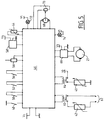
- FIG. 5 shows the assembly diagram of the components of an installation according to the invention.
- the installation shown in FIG. 1 is intended to equip an electric motor vehicle equipped with batteries which deliver on the one hand a continuous low voltage V1, for example of 12 V and, on the other hand, a continuous high voltage V2, by example of 110 V.
- the voltage V1 is intended for supplying the usual accessories of the motor vehicle, while the voltage V2 is intended for supplying the electric propulsion motor of the vehicle and also for supplying the heating radiator 40 .
- the installation comprises an electronic management module 46 supplied with voltage V1.
- This module is connected, at input, to a network contact switch 48 supplied with voltage V1, to a heating switch 50, to a preheating switch 52, to an outside air / recycled air switch 54, to a control 56 of the voltage of the pulser 22, to a preheating programming clock 58 and to the temperature sensor 44.
- the module 46 is connected to a preheating switch 60 mounted on the power supply circuit of the preheating radiator 42, the latter being provided with a power outlet 62 on the 220 V AC sector.
- the module 46 is further connected at the output to a heating contactor 64 mounted on the supply circuit of the heating radiator 40, the latter being suitable for being supplied by the voltage V2.
- the module 46 is further connected, at the output, to a control module 66 acting on the motor 21 of the blower 20 and supplied with voltage V1, to a geared motor 68 actuating the air inlet flap 16 (FIG. 1) , this geared motor acting on a feedback device 70.
- the electronic management module is connected to a preheating indicator 72 and a heating indicator 74, both supplied at voltage V1.
- the electronic management module 46 is produced from known electronic components and operates as follows.
- the module 46 acts on the control module 66 of the blower 20, so that this blower can be controlled manually over its entire range. command range. It is therefore possible to adjust the air flow over the entire amplitude of flow authorized by the blower.
- the electronic module 46 acts on the control module 66 so that the blower can be controlled manually over a range depending on the input temperature d air, and this in accordance with the diagram of Figure 6.
- the blower 20 is supplied normally at a maximum voltage U max corresponding to V1.
- U max maximum voltage
- the blower 20 is supplied with the aforementioned maximum voltage.
- the supply voltage of the blower decreases progressively to avoid having too much air flow in the heating branch 24
- the value of the PTC resistance increases, which results in a reduction in the electrical consumption.
- This function of limiting the air flow of the blower 20 makes it possible to have a limited electrical power consumption, if necessary, as well as a supply air temperature greater than a minimum defined by the feeling of comfort.
- the heating contactor 64 is activated if the following conditions are met: the network contact switch 48 is closed and the heating switch 50 is also closed. Under these conditions, the heating indicator light 74 is on.
- the preheating switch 60 is activated if the following conditions are met: the network contact switch 48 is open, the preheating switch 52 is closed and the programming clock 58 is started. Under these conditions, the preheating indicator light 72 is on.
- the air inlet flap 76 is controlled by the geared motor 68 and can take two extreme positions: a closed position of the outside air intake pipe 10 and another closed position of the inlet pipe 12 recycled air, as well as any intermediate position between the two aforementioned extreme positions.
- the shutter 16 is placed in the "outside air” position, in which the line 12 is closed, if the following conditions are met: the network contact switch 48 is closed, the heating switch is open and the switch recycling is also open.
- the air inlet flap 16 goes into the recycling position in which the outside air intake pipe 10 is closed, in order to improve the heating and preheating performance.
- the flap 16 can be placed in a 100% recycling position or in an intermediate position.
- the electrical power consumed adapts to the desired thermal power.
- the installation can be adjusted so that the temperature minimum of the air blown into the passenger compartment, for example 40 ° C.
- the temperature of the blown air is always greater than 40 ° C. and that the electrical power consumed remains constant within less than 5%.
- FIG. 7 shows another alternative embodiment in which the installation comprises a single electric radiator 76, of the PTC resistance type, which can be used both for the heating mode and the preheating mode.
- the installation includes a plug 78 suitable for being connected to the 220 V AC sector.
- This socket 78 makes it possible to supply a battery charger 80 suitable for supplying the batteries 82 on board the vehicle.
- the batteries 82 make it possible to power an assembly 84 which notably comprises the motor driving the vehicle. This supply takes place when a contact 86 is closed.
- the outlet 78 supplies, in parallel, the radiator 76 through a full-wave rectifier 88 when a contact 90 is closed.
- the rectifier 88 is interposed on a line 91 between the socket 78 and the radiator 76.
- the radiator 76 can be supplied by the batteries 82 through another line 92 on which a heating switch 94 is placed.
- radiator 62 can be used either as a heating radiator when the heating contactor 94 is closed, or as a preheating radiator when the preheating contactor 90 is closed.
- the nominal voltage Un of the vehicle on-board network is equal to 110 V DC with 0.8 x Un ⁇ Ureal ⁇ 1.4 x Un.
- the circuit shown in FIG. 7 can be mounted on a management module 46 as shown previously in FIG. 5.
Landscapes
- Physics & Mathematics (AREA)
- Thermal Sciences (AREA)
- Engineering & Computer Science (AREA)
- Mechanical Engineering (AREA)
- Air-Conditioning For Vehicles (AREA)
Applications Claiming Priority (2)
| Application Number | Priority Date | Filing Date | Title |
|---|---|---|---|
| FR9112692A FR2682328B1 (fr) | 1991-10-15 | 1991-10-15 | Installation de chauffage de l'habitacle d'un vehicule automobile, notamment d'un vehicule a propulsion electrique. |
| FR9112692 | 1991-10-15 |
Publications (2)
| Publication Number | Publication Date |
|---|---|
| EP0538131A1 true EP0538131A1 (de) | 1993-04-21 |
| EP0538131B1 EP0538131B1 (de) | 1996-05-15 |
Family
ID=9417928
Family Applications (1)
| Application Number | Title | Priority Date | Filing Date |
|---|---|---|---|
| EP19920402818 Expired - Lifetime EP0538131B1 (de) | 1991-10-15 | 1992-10-15 | Vorrichtung zur Heizung des Fahrgastraums eines Kraftfahrzeuge, insbesondere für einen elektrischen Wagen |
Country Status (4)
| Country | Link |
|---|---|
| EP (1) | EP0538131B1 (de) |
| DE (1) | DE69210748T2 (de) |
| ES (1) | ES2089453T3 (de) |
| FR (1) | FR2682328B1 (de) |
Cited By (7)
| Publication number | Priority date | Publication date | Assignee | Title |
|---|---|---|---|---|
| EP0595699A1 (de) * | 1992-10-26 | 1994-05-04 | Valeo Thermique Habitacle | Stellgerät an Kühl- und Klimaanlage für ein Elektrofahrzeug |
| FR2706816A1 (en) * | 1993-06-23 | 1994-12-30 | Valeo Thermique Habitacle | Apparatus for heating-ventilating and/or air-conditioning the passenger compartment of a motor vehicle, especially an electric vehicle |
| EP1626231A1 (de) * | 2004-08-13 | 2006-02-15 | Behr France S.A.R.L. | Heizungsanordnung mit elektrischen Heizelementen, insbesondere für ein Kraftfahrzeug |
| EP1630488A1 (de) * | 2004-08-13 | 2006-03-01 | Behr France Rouffach SAS | Heizungsanordnung mit elektrischen Heizelementen, insbesondere für ein Kraftfahrzeug |
| EP1780061A1 (de) * | 2005-10-26 | 2007-05-02 | Behr France Rouffach S.A.R.L. | Heizungsanordnung mit elektrischen Heizelementen für ein Kraftfahrzeug |
| US20160200172A1 (en) * | 2013-08-27 | 2016-07-14 | Denso Corporation | In-vehicle radiant heater control apparatus |
| CN107000541A (zh) * | 2014-12-10 | 2017-08-01 | 法雷奥热系统公司 | 用于机动车辆的空调装置 |
Families Citing this family (3)
| Publication number | Priority date | Publication date | Assignee | Title |
|---|---|---|---|---|
| FR2746712B1 (fr) * | 1996-03-28 | 1998-06-12 | Valeo Climatisation | Installation de chauffage, ventilation et/ou climatisation, a regulation de puissance, notamment pour vehicule automobile |
| DE102012021727A1 (de) * | 2012-11-05 | 2014-05-08 | Volkswagen Aktiengesellschaft | Heizeinrichtung für ein Kraftfahrzeug |
| CN113085475B (zh) * | 2021-03-25 | 2022-10-28 | 青岛海尔空调器有限总公司 | 车载顶置式空调器及其控制方法、车辆 |
Citations (6)
| Publication number | Priority date | Publication date | Assignee | Title |
|---|---|---|---|---|
| US3673379A (en) * | 1970-03-20 | 1972-06-27 | Richard F Eversull | Motor vehicle warm-up and battery charger system |
| FR2214605A1 (de) * | 1972-06-07 | 1974-08-19 | Wikstroem Ab Berth | |
| FR2392521A1 (fr) * | 1977-05-28 | 1978-12-22 | Sueddeutsche Kuehler Behr | Circuit a protection contre les surcharges pour le reglage graduel de la puissance des moteurs electriques de ventilateurs |
| US4459466A (en) * | 1980-11-26 | 1984-07-10 | Nippon Soken, Inc. | Dual air passage heating apparatus with ceramic heater element |
| EP0243077A2 (de) * | 1986-04-17 | 1987-10-28 | Ford Motor Company Limited | Elektrisches Heizelement für Kraftfahrzeuge |
| EP0275720A2 (de) * | 1987-01-20 | 1988-07-27 | Ford Motor Company Limited | Heizungssystem für Fahrzeuge mit mehreren unabhängigen Wärmequellen |
Family Cites Families (2)
| Publication number | Priority date | Publication date | Assignee | Title |
|---|---|---|---|---|
| JPH0253628A (ja) * | 1988-08-17 | 1990-02-22 | Texas Instr Japan Ltd | 空気加熱装置 |
| JP2797497B2 (ja) * | 1989-08-09 | 1998-09-17 | 株式会社デンソー | 車両用暖房装置 |
-
1991
- 1991-10-15 FR FR9112692A patent/FR2682328B1/fr not_active Expired - Fee Related
-
1992
- 1992-10-15 EP EP19920402818 patent/EP0538131B1/de not_active Expired - Lifetime
- 1992-10-15 DE DE1992610748 patent/DE69210748T2/de not_active Expired - Fee Related
- 1992-10-15 ES ES92402818T patent/ES2089453T3/es not_active Expired - Lifetime
Patent Citations (6)
| Publication number | Priority date | Publication date | Assignee | Title |
|---|---|---|---|---|
| US3673379A (en) * | 1970-03-20 | 1972-06-27 | Richard F Eversull | Motor vehicle warm-up and battery charger system |
| FR2214605A1 (de) * | 1972-06-07 | 1974-08-19 | Wikstroem Ab Berth | |
| FR2392521A1 (fr) * | 1977-05-28 | 1978-12-22 | Sueddeutsche Kuehler Behr | Circuit a protection contre les surcharges pour le reglage graduel de la puissance des moteurs electriques de ventilateurs |
| US4459466A (en) * | 1980-11-26 | 1984-07-10 | Nippon Soken, Inc. | Dual air passage heating apparatus with ceramic heater element |
| EP0243077A2 (de) * | 1986-04-17 | 1987-10-28 | Ford Motor Company Limited | Elektrisches Heizelement für Kraftfahrzeuge |
| EP0275720A2 (de) * | 1987-01-20 | 1988-07-27 | Ford Motor Company Limited | Heizungssystem für Fahrzeuge mit mehreren unabhängigen Wärmequellen |
Non-Patent Citations (2)
| Title |
|---|
| PATENT ABSTRACTS OF JAPAN vol. 14, no. 221 (M-971)(4164) 10 Mai 1990 & JP-A-02 053 628 ( TEXAS INSTR JAPAN LTD ) 22 Février 1990 * |
| PATENT ABSTRACTS OF JAPAN vol. 15, no. 228 (M-1123)11 Juin 1991 & JP-A-03 070 621 ( NIPPON DENSO ) 26 Mars 1991 * |
Cited By (9)
| Publication number | Priority date | Publication date | Assignee | Title |
|---|---|---|---|---|
| EP0595699A1 (de) * | 1992-10-26 | 1994-05-04 | Valeo Thermique Habitacle | Stellgerät an Kühl- und Klimaanlage für ein Elektrofahrzeug |
| FR2706816A1 (en) * | 1993-06-23 | 1994-12-30 | Valeo Thermique Habitacle | Apparatus for heating-ventilating and/or air-conditioning the passenger compartment of a motor vehicle, especially an electric vehicle |
| US5478274A (en) * | 1993-06-23 | 1995-12-26 | Valeo Thermique Habitacle | Heating and ventilating, and/or air conditioning, apparatus for the cabin of a motor vehicle, especially an electric vehicle |
| EP1626231A1 (de) * | 2004-08-13 | 2006-02-15 | Behr France S.A.R.L. | Heizungsanordnung mit elektrischen Heizelementen, insbesondere für ein Kraftfahrzeug |
| EP1630488A1 (de) * | 2004-08-13 | 2006-03-01 | Behr France Rouffach SAS | Heizungsanordnung mit elektrischen Heizelementen, insbesondere für ein Kraftfahrzeug |
| EP1780061A1 (de) * | 2005-10-26 | 2007-05-02 | Behr France Rouffach S.A.R.L. | Heizungsanordnung mit elektrischen Heizelementen für ein Kraftfahrzeug |
| US20160200172A1 (en) * | 2013-08-27 | 2016-07-14 | Denso Corporation | In-vehicle radiant heater control apparatus |
| US10004111B2 (en) * | 2013-08-27 | 2018-06-19 | Denso Corporation | In-vehicle radiant heater control apparatus |
| CN107000541A (zh) * | 2014-12-10 | 2017-08-01 | 法雷奥热系统公司 | 用于机动车辆的空调装置 |
Also Published As
| Publication number | Publication date |
|---|---|
| EP0538131B1 (de) | 1996-05-15 |
| DE69210748T2 (de) | 1996-10-02 |
| ES2089453T3 (es) | 1996-10-01 |
| DE69210748D1 (de) | 1996-06-20 |
| FR2682328B1 (fr) | 1995-03-24 |
| FR2682328A1 (fr) | 1993-04-16 |
Similar Documents
| Publication | Publication Date | Title |
|---|---|---|
| EP0554169B1 (de) | Vorrichtung für die Heizung und Lüftung des Innenraums von Motorfahrzeugen mit geringer Wärmeabgabe des Motors | |
| EP0567402B1 (de) | Vorrichtung für die Heizung und Lüftung des Innenraums von Motorfahrzeugen mit geringer Wärmeabgabe des Motors | |
| EP0538131B1 (de) | Vorrichtung zur Heizung des Fahrgastraums eines Kraftfahrzeuge, insbesondere für einen elektrischen Wagen | |
| FR2864715A1 (fr) | Systeme de commande de vehicule par calcul de l'augmentation du couple d'entrainement d'un generateur a courant alternatif | |
| EP0558412B1 (de) | Heiz- und/oder Kühlvorrichtung für ein Elektrofahrzeug | |
| EP0566475B1 (de) | Klimaanlage für ein elektrisches Fahrzeug | |
| EP0715979A1 (de) | Klimavorrichtung für ein abgestelltes und fahrendes Fahrzeug | |
| EP0611675A1 (de) | Fahrzeug mit elektrischem Antrieb mit einer Vorrichtung zur Rückgewinnung der Energie | |
| EP0782265B1 (de) | Verfahren und Vorrichtung zum Schutz eines einstellbaren Impedanzelements zur Steuerung der Stromversorgung eines Elektromotors, insbesondere eines Kraftfahrzeugs | |
| EP0484205A1 (de) | Vorrichtung zur Heizung und Belüftung des Fahrgastraums eines Kraftfahrzeugs | |
| EP3468824A1 (de) | Lufteinlassmanagementsystem für die frontseite eines kraftfahrzeugs | |
| EP0445015A1 (de) | Geschwindigkeitskommutationsvorrichtung für einen elektrischen Motor | |
| FR2995839A1 (fr) | Systeme de gestion d'un prolongateur d'autonomie d'un vehicule a propulsion electrique | |
| FR2808304A1 (fr) | Dispositif de refroidissement a l'arret d'un moteur thermique de vehicule automobile | |
| WO2020157270A1 (fr) | Procédé de chauffage d'un réservoir | |
| FR2720695A1 (fr) | Dispositif de chauffage et/ou de climatisation de l'habitacle d'un véhicule. | |
| FR3013638A1 (fr) | Dispositif de commande du chauffage dans un vehicule | |
| EP1234697B1 (de) | Verfahren und Vorrichtung zum Beheizen von einem Innenraum eines Fahrzeuges ausgerüstet mit einer Brennstoffzellenanlage | |
| EP1093944B1 (de) | Klima- oder Heizanlage für den Fahrgastraum eines Kraftfahrzeugs, ausgerüstet mit einer zusätzlichen Wärmequelle | |
| FR3072613A1 (fr) | Dispositif de chauffage, notamment pour boitier de climatisation d'un vehicule automobile | |
| FR2882864A1 (fr) | Circuit electrique muni d'un generateur secondaire de tension pour la fourniture d'electricite dans un habitacle de vehicule automobile. | |
| FR2878316A1 (fr) | Dispositif de chauffage electrique, notamment pour appareil de chauffage, de ventilation et/ou de climatisation de vehicule | |
| WO2021053278A1 (fr) | Dispositif de conditionnement thermique des batteries à haut voltage pour véhicules hybrides | |
| EP3766303A1 (de) | Heizvorrichtung, insbesondere für klimaanlagengehäuse eines kraftfahrzeugs | |
| FR2885269A1 (fr) | Systeme de pilotage de la tension d'un reseau electrique de bord d'un vehicule automobile |
Legal Events
| Date | Code | Title | Description |
|---|---|---|---|
| PUAI | Public reference made under article 153(3) epc to a published international application that has entered the european phase |
Free format text: ORIGINAL CODE: 0009012 |
|
| AK | Designated contracting states |
Kind code of ref document: A1 Designated state(s): DE ES GB IT |
|
| 17P | Request for examination filed |
Effective date: 19930811 |
|
| 17Q | First examination report despatched |
Effective date: 19950314 |
|
| GRAH | Despatch of communication of intention to grant a patent |
Free format text: ORIGINAL CODE: EPIDOS IGRA |
|
| GRAA | (expected) grant |
Free format text: ORIGINAL CODE: 0009210 |
|
| RAP1 | Party data changed (applicant data changed or rights of an application transferred) |
Owner name: VALEO CLIMATISATION |
|
| AK | Designated contracting states |
Kind code of ref document: B1 Designated state(s): DE ES GB IT |
|
| REF | Corresponds to: |
Ref document number: 69210748 Country of ref document: DE Date of ref document: 19960620 |
|
| ITF | It: translation for a ep patent filed |
Owner name: SOCIETA' ITALIANA BREVETTI S.P.A. |
|
| GBT | Gb: translation of ep patent filed (gb section 77(6)(a)/1977) |
Effective date: 19960814 |
|
| REG | Reference to a national code |
Ref country code: ES Ref legal event code: FG2A Ref document number: 2089453 Country of ref document: ES Kind code of ref document: T3 |
|
| REG | Reference to a national code |
Ref country code: ES Ref legal event code: FG2A Ref document number: 2089453 Country of ref document: ES Kind code of ref document: T3 |
|
| PLBE | No opposition filed within time limit |
Free format text: ORIGINAL CODE: 0009261 |
|
| STAA | Information on the status of an ep patent application or granted ep patent |
Free format text: STATUS: NO OPPOSITION FILED WITHIN TIME LIMIT |
|
| 26N | No opposition filed | ||
| PGFP | Annual fee paid to national office [announced via postgrant information from national office to epo] |
Ref country code: GB Payment date: 19991008 Year of fee payment: 8 |
|
| PGFP | Annual fee paid to national office [announced via postgrant information from national office to epo] |
Ref country code: DE Payment date: 19991013 Year of fee payment: 8 |
|
| PGFP | Annual fee paid to national office [announced via postgrant information from national office to epo] |
Ref country code: ES Payment date: 19991015 Year of fee payment: 8 |
|
| PG25 | Lapsed in a contracting state [announced via postgrant information from national office to epo] |
Ref country code: GB Free format text: LAPSE BECAUSE OF NON-PAYMENT OF DUE FEES Effective date: 20001015 |
|
| PG25 | Lapsed in a contracting state [announced via postgrant information from national office to epo] |
Ref country code: ES Free format text: LAPSE BECAUSE OF NON-PAYMENT OF DUE FEES Effective date: 20001016 |
|
| GBPC | Gb: european patent ceased through non-payment of renewal fee |
Effective date: 20001015 |
|
| PG25 | Lapsed in a contracting state [announced via postgrant information from national office to epo] |
Ref country code: DE Free format text: LAPSE BECAUSE OF NON-PAYMENT OF DUE FEES Effective date: 20010703 |
|
| REG | Reference to a national code |
Ref country code: ES Ref legal event code: FD2A Effective date: 20011113 |
|
| PG25 | Lapsed in a contracting state [announced via postgrant information from national office to epo] |
Ref country code: IT Free format text: LAPSE BECAUSE OF NON-PAYMENT OF DUE FEES Effective date: 20051015 |