EP0484205A1 - Vorrichtung zur Heizung und Belüftung des Fahrgastraums eines Kraftfahrzeugs - Google Patents
Vorrichtung zur Heizung und Belüftung des Fahrgastraums eines Kraftfahrzeugs Download PDFInfo
- Publication number
- EP0484205A1 EP0484205A1 EP91402830A EP91402830A EP0484205A1 EP 0484205 A1 EP0484205 A1 EP 0484205A1 EP 91402830 A EP91402830 A EP 91402830A EP 91402830 A EP91402830 A EP 91402830A EP 0484205 A1 EP0484205 A1 EP 0484205A1
- Authority
- EP
- European Patent Office
- Prior art keywords
- shutter
- air
- inlet
- intake
- priority
- Prior art date
- Legal status (The legal status is an assumption and is not a legal conclusion. Google has not performed a legal analysis and makes no representation as to the accuracy of the status listed.)
- Granted
Links
Images


Classifications
-
- B—PERFORMING OPERATIONS; TRANSPORTING
- B60—VEHICLES IN GENERAL
- B60H—ARRANGEMENTS OF HEATING, COOLING, VENTILATING OR OTHER AIR-TREATING DEVICES SPECIALLY ADAPTED FOR PASSENGER OR GOODS SPACES OF VEHICLES
- B60H1/00—Heating, cooling or ventilating devices
- B60H1/00007—Combined heating, ventilating, or cooling devices
- B60H1/00021—Air flow details of HVAC devices
- B60H1/00035—Air flow details of HVAC devices for sending an air stream of uniform temperature into the passenger compartment
- B60H1/00042—Air flow details of HVAC devices for sending an air stream of uniform temperature into the passenger compartment the air passing only one heat exchanger
-
- B—PERFORMING OPERATIONS; TRANSPORTING
- B60—VEHICLES IN GENERAL
- B60H—ARRANGEMENTS OF HEATING, COOLING, VENTILATING OR OTHER AIR-TREATING DEVICES SPECIALLY ADAPTED FOR PASSENGER OR GOODS SPACES OF VEHICLES
- B60H1/00—Heating, cooling or ventilating devices
- B60H1/00007—Combined heating, ventilating, or cooling devices
- B60H1/00021—Air flow details of HVAC devices
- B60H2001/0015—Temperature regulation
- B60H2001/00171—Valves on heaters for modulated liquid flow
Definitions
- the invention relates to a device for heating and ventilating the passenger compartment of a motor vehicle.
- Devices of this type which include: a cold air intake pipe; an intake and heating circuit connected to the cold air intake pipe and suitable for producing a flow of cold or heated air; a distribution circuit connected to the intake and heating circuit and comprising an inlet for the flow of cold or heated air, as well as air outlet pipes supplied by this air inlet and suitable for distribution, by distribution means, the air flow in different areas of the passenger compartment, at least one of said outlet pipes opening behind the windshield for its demisting.
- Such devices are usually used for heating and ventilating - and possibly air conditioning - the passenger compartment of motor vehicles. They are then used to send cold or heated air to different areas of the passenger compartment using the aforementioned outlet pipes.
- these are three in number and include: the aforementioned outlet pipe serving defogging / defrosting openings of the windshield, a pipe serving aerators at the dashboard level and a pipe serving a mouth at the bottom of the passenger compartment.
- the cold air coming from outside the passenger compartment or possibly from an air conditioning unit, is adjusted in temperature by the intake and heating circuit before being distributed in the passenger compartment.
- these devices comprise, in a manner known per se, a motor-fan unit disposed upstream of the cold air intake pipe to regulate the speed of the air flow which is sent into the passenger compartment.
- Most devices of this type include manual, mechanical or electrical control members for regulating the temperature of the air flow, its distribution between the various outlet pipes and also its ventilation speed.
- the object of the invention is in particular to remedy the aforementioned drawbacks.
- a heating and ventilation device of the type defined in the introduction which, in accordance with the invention, comprises a defog pipe separate from the distribution circuit, called priority defog pipe and having an input communicating with the intake and heating circuit and an outlet opening behind the windshield, a shutter movable between a position called “priority defogging" where it closes the entry of the distribution circuit and a position called “normal use” where it closes the entry of the priority demisting pipe, and means for controlling the movement of the shutter between the two aforementioned positions.
- the flow of cold or heated air flows through the "priority defogging" pipe to open behind the vehicle windshield, while the distribution circuit is rendered inoperative.
- the various settings of the heating and ventilation device are retained, in particular the settings provided by the distribution means.
- the term "demisting” means any action capable of sending air, preferably heated, behind the vehicle windshield to ensure its demisting or defrosting, as the case may be.
- the intake and heating circuit comprises a cold air transmission branch interposed between the cold air intake pipe and the inlet of the distribution circuit; an air heating branch interposed between the cold air intake pipe and the inlet of the distribution circuit and containing a heat exchanger; and a mixing shutter capable of varying the distribution of the air flow between these two branches.
- the device further comprises an auxiliary cold air intake which opens directly into the air heating branch upstream of the heat exchanger, as well as an auxiliary shutter movable between a closed position and an open position of this auxiliary cold air intake.
- the auxiliary shutter is movable in synchronism with the shutter so as to be in the open position when the shutter is in the priority demister position and in the closed position when the shutter shutter is in normal use position.
- the intake and heating circuit comprises a branch single intake interposed between the cold air intake pipe and the inlet of the distribution circuit, said intake branch containing a heat exchanger supplied by a heat transfer fluid via an adjusting member of debt.
- the device comprises means for controlling said flow-adjusting member which are synchronized with the means for controlling movement of the shutter, so that the flow of heat-transfer fluid through the heat exchanger is increased when the shutter is in the priority demisting position.
- the intake and heating circuit comprises a branch for transmitting cold air controlled by a flow control flap, and a heating branch containing a heat exchanger supplied by a heat transfer fluid via a flow control member, the two aforementioned branches being interposed between, on the one hand, the cold air intake pipe and, on the other hand, the air inlet of the distribution circuit and the air inlet of the demister pipe.
- the device further comprises means for controlling the shutter for adjusting the cold air flow which are synchronized with the means for controlling the shutter so that the shutter for adjusting the air flow cold closes the cold air transmission branch when the shutter is in the priority demisting position.
- the device comprises a probe capable of detecting the presence of fogging or frost or the risk of fogging or frost on the windshield.
- This probe can inform the driver, for example by means of an indicator light, that fogging or frost is forming or may deform behind the windshield.
- the driver will then have to press a key automatically controlling the means for adjusting the device in the priority demisting position.
- the driver may have to move a lever to a priority demister position.
- the probe is connected to an electronic module suitable for controlling the shutter and possibly other control means synchronized with the shutter.
- the electronic module is capable of actuating the speed of the blower to an optimal value, for example maximum, when the shutter is in the priority demisting position.
- the air intake pipe is advantageously connected to an air inlet mouth controlled by an air inlet flap movable between an open position and a closed position of this mouth.
- the device further comprises means for controlling the air inlet shutter which are synchronized with the means for controlling the shutter shutter so that the air inlet shutter is necessarily in position d opening when the shutter is in the priority defrost position.
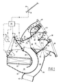
- the device shown in Figure 1 comprises a housing 10 having a cold air intake pipe 12 which is connected to the outlet nozzle 14 of a motor-fan unit (not shown) equipped with a clean blower 16 to send cold air coming from outside the passenger compartment of the vehicle or possibly from an air conditioning unit into the intake pipe 12.
- the intake pipe 12 is connected to an intake and heating circuit comprising a cold air transmission branch 18 and an air heating branch 20 which has a U-shaped configuration and which contains a heat exchanger 22 which is, for example, continuously supplied by the vehicle engine coolant.
- the branch 18 is externally limited by a portion wall 24, while the branch 20 is externally limited by a curved wall portion 26.
- the branch 20 thus constitutes a sort of pocket which internally comprises a wall 28 to define a U-shaped circulation therein.
- the air transmission branch cold 18 extends directly between the two ends of the U-shaped heating branch 20.
- the device further comprises a mixing flap 30 mounted in rotation about an axis 32 and disposed at the junction of the intake pipe 12 and the branches 18 and 20 to vary the distribution, between these two branches, of the flow of air arriving through the intake pipe 12 and, consequently, the temperature of the air leaving the branches 18 and 20.
- the mixing flap 30 is movable between a position A (shown in solid lines) where the air circulates only in the air heating branch 20 and a position B (shown in dashed lines) where the air circulates only through the cold air transmission branch 18, while being able to take any intermediate position.
- The: branches 18 and 20 communicate with each other, at their outlet, by a mixing zone 34 intended to ensure the mixing of the cold air coming from the branch 18 and the hot air coming from the branch 20.
- the flow of cold or heated air thus obtained at the outlet of the intake and heating circuit can penetrate at the inlet 36 of a distribution circuit 38.
- the circuit 38 includes a first outlet pipe 40 limited mainly by two sections of cylindrical walls 42 and 44 and serving at least one demister / defroster mouth 46 to send cold or heated air behind the windshield 69 of the vehicle.
- the distribution of air through the pipe 40 is controlled by a distribution flap 48 mounted in rotation about an axis 50.
- the circuit 38 further comprises a second outlet line 52 mainly limited by two cylindrical wall portions 54 and 56 and serving at least one air vent 58 disposed at the level of the dashboard of the vehicle.
- the circuit 38 further comprises a third outlet pipe 60 which serves an outlet mouth 62 in the lower part of the passenger compartment.
- a second distribution flap 64 rotatably mounted around an axis 65 is provided to control the distribution of air through the outlet pipes 52 and 60.
- the flaps 48 and 64 are synchronized with one another so that they can take five different positions identified respectively by the symbols V (ventilation), BL (bi-level, i.e. temperature stratification), P (feet), DC (defrost-heating) and D (defrost).
- the device as just described above, has a known general structure.
- the device further comprises a defogging pipe 66, also called a "priority defogging" pipe, which is separated from the distribution circuit 38.
- the pipe 66 has an inlet 67 which communicates with the intake circuit for reheating, and more particularly with the mixing zone 34, as well as an outlet 68 opening out behind the windshield 69, near the outlet mouth 46.
- the device further comprises a shutter 70 movable between a position called “priority demister” or “DP” (shown in broken lines in Figure 1) where it closes the inlet 36 of the distribution circuit 38 and a position called “normal use” or “UN” (shown in solid lines in Figure 1) where the flap closes the inlet 67 of the pipe 66.
- DP priority demister
- UN normal use
- the movement of the flap 70 between the two aforementioned positions can be done by means manual, mechanical or electrical controls such as by means of a micromotor (not shown).
- the flow of cold or heated air penetrates through the inlet 36 of the distribution circuit and can be distributed between the various outlet pipes thanks to the two distribution flaps 48 and 64.
- the shutter 70 is operated to bring it into the priority defrost position (DP) and the air flow is brought directly behind the windshield via the pipe 66, without the need to change the setting of the distribution flaps.
- DP priority defrost position
- the device of the invention further comprises an auxiliary cold air intake 72 which is adjacent to the intake pipe 12 and which opens directly into the air heating branch 20, upstream of the heat exchanger 22 There is further provided an auxiliary shutter 74 movable between a closed position (shown in solid lines) where it closes the auxiliary inlet 72 and an open position (shown in broken lines) where it does not close not auxiliary admission 72.
- the auxiliary shutter 72 is movable in synchronism with the shutter 70 so as to be in the open position when the shutter is in the priority demister (DP) position and in the position closing when the shutter is in the normal use position (UN).
- the synchronization of the flaps 70 and 72 can be carried out by conventional mechanical means and the synchronized movement of the two flaps can be carried out manually or else by means of a micromotor.
- the device comprises a probe 76 placed behind the windshield 69 and suitable for detecting the presence or the risk of the appearance of mist or frost behind the windshield.
- This probe is connected to an electronic module 78 capable of controlling the synchronized movement of the flaps 70 and 72 as well as, if necessary, the control of the air blower 16 to bring it to an increased speed.
- the flap 70 closes the inlet 67 of the pipe 66, while the flap 74 closes the auxiliary inlet 72.
- the temperature of the air flow entering the distribution circuit is adjusted by means of the adjustment flap 30 and the distribution of this flow is ensured by the distribution flaps 48 and 64.
- the module 78 acts on the flaps 70 and 74 to bring them into the so-called priority defrost position where the flap 70 closes the inlet 36 of the distribution circuit and the shutter 74 releases the auxiliary intake 72.
- the air is sent into the priority defrost line 66.
- the electronic module is adjusted so that the ventilation speed of the blower 16 is then increased while keeping in memory the initial speed of the blower.
- this circuit comprises a single intake branch 80 interposed between the cold air intake pipe 12 and the area 34 which opens at the same time on the inlet 36 of the distribution circuit 38 and on the inlet 67 of the demister pipe 66.
- the intake branch 80 contains a heat exchanger 82 supplied with a heat transfer fluid (for example the vehicle engine cooling fluid) via a flow control member 84, such as a solenoid valve.
- a heat transfer fluid for example the vehicle engine cooling fluid
- a flow control member 84 such as a solenoid valve.
- the air flow suitable for supplying the circuit 38 or the pipe 64 is adjusted in temperature.
- the device comprises means 86 for controlling the flow control member 84, which are synchronized with the means for controlling the movement of the shutter 70 so that the flow of heat transfer fluid through the heat exchanger is increased, or maintained at the maximum value when the shutter is in the priority demisting position (shown in broken lines in Figure 2).
- the control means 86 are controlled for example by the electronic module 78 which will keep in memory the initial setpoint of the means 86.
- the air intake pipe 12 is connected to an air inlet mouth 88 controlled by an air inlet flap 90 movable between a closed position (shown in solid lines ) of the mouth and an open position (shown in broken lines) of this mouth.
- the mouth 88 is formed through the body of the motor vehicle and allows the device to be supplied with fresh air taken from outside the passenger compartment.
- the device further comprises means 92 for controlling the air inlet flap 90, which are synchronized with the control means 94 for the shutter 70 so that the air inlet flap 90 must be in position. opening (shown in broken lines) when the shutter is in the priority defrost position (shown in broken lines).
- the control means 92 and 94 are also synchronized with the control means 86 of the flow control member 84.
- the member 84 is adjusted so that the heat transfer fluid which passes through the heat exchanger 82 either at an increased temperature, or maintained at the maximum value.
- Figure 4 shows a third embodiment of the device of the invention, which differs from that of Figure 1 by the structure of the intake and heating circuit.
- the intake and heating circuit comprises a cold air transmission branch 18 controlled by a flow control flap 96 and an air heating branch 20 containing a heat exchanger 98 supplied by a heat transfer fluid via a flow control member 100.
- the branches 18 and 20 are connected, on the one hand, to the intake pipe 12 and, on the other hand, to the zone 34 supplying both the inlet 36 of said distribution circuit 38 and the inlet 67 of the priority demister branch 66.
- the device comprises means 102 for controlling the shutter for adjusting the cold air flow 96 and means for controlling 104 the shutter 70.
- control means 104 are advantageously synchronized with the control means 106 of the flow control member 100 so that, in the priority demister position, the temperature of the heat transfer fluid passing through the heat exchanger 98 is increased , or maintained at the maximum value.
- the probe can simply light an indicator light to signal to the driver that he must act on a command suitable for bringing the device to the priority defrost position. It may be a manual control or a control acting on micromotors controlling the various adjustment members of the device.
- the speed of the air blower 16 (Fig. 1) be increased.
- the air blower comprises an electric motor M which can take four different speeds by being supplied directly or through three resistors R1, R2 and R3 of different values which can be selectively switched on by the intermediate of a rheostat 110.
- the probe 76 can then increase or maintain the speed of the motor at the maximum value by acting on a contactor 112 to switch on the motor with a resistor R of appropriate value.
Landscapes
- Physics & Mathematics (AREA)
- Thermal Sciences (AREA)
- Engineering & Computer Science (AREA)
- Mechanical Engineering (AREA)
- Air-Conditioning For Vehicles (AREA)
- Duct Arrangements (AREA)
Applications Claiming Priority (2)
| Application Number | Priority Date | Filing Date | Title |
|---|---|---|---|
| FR9013568 | 1990-10-31 | ||
| FR909013568A FR2668429B1 (fr) | 1990-10-31 | 1990-10-31 | Dispositif de chauffage et de ventilation de l'habitacle d'un vehicule automobile. |
Publications (2)
| Publication Number | Publication Date |
|---|---|
| EP0484205A1 true EP0484205A1 (de) | 1992-05-06 |
| EP0484205B1 EP0484205B1 (de) | 1995-12-20 |
Family
ID=9401767
Family Applications (1)
| Application Number | Title | Priority Date | Filing Date |
|---|---|---|---|
| EP91402830A Expired - Lifetime EP0484205B1 (de) | 1990-10-31 | 1991-10-23 | Vorrichtung zur Heizung und Belüftung des Fahrgastraums eines Kraftfahrzeugs |
Country Status (6)
| Country | Link |
|---|---|
| US (1) | US5173078A (de) |
| EP (1) | EP0484205B1 (de) |
| JP (1) | JPH0687326A (de) |
| DE (1) | DE69115647T2 (de) |
| ES (1) | ES2082948T3 (de) |
| FR (1) | FR2668429B1 (de) |
Cited By (4)
| Publication number | Priority date | Publication date | Assignee | Title |
|---|---|---|---|---|
| FR2728511A1 (fr) * | 1994-12-22 | 1996-06-28 | Valeo Thermique Habitacle | Dispositif de chauffage et/ou de climatisation, notamment pour vehicule automobile |
| AU690051B1 (en) * | 1997-04-01 | 1998-04-09 | Calsonic Corporation | Heater/cooler unit of automotive air conditioning device |
| FR2793738A1 (fr) * | 1999-01-16 | 2000-11-24 | Daimler Chrysler Ag | Dispositif de ventilation pour vehicules |
| EP0756955B1 (de) * | 1995-08-04 | 2003-11-05 | Ford Motor Company | Luftbehandlungssystem für Kraftfahrzeuge |
Families Citing this family (15)
| Publication number | Priority date | Publication date | Assignee | Title |
|---|---|---|---|---|
| EP0663309B1 (de) * | 1993-12-20 | 1995-09-20 | Siemens Aktiengesellschaft | Heiz- bzw. Klimagerät, insbesondere zum Einbau in ein Kraftfahrzeug |
| JP3449071B2 (ja) * | 1995-10-26 | 2003-09-22 | 株式会社日本自動車部品総合研究所 | 自動車用空調装置 |
| KR100316163B1 (ko) * | 1996-07-27 | 2002-12-05 | 한라공조주식회사 | 공기조화장치 |
| GB2323158A (en) * | 1997-03-13 | 1998-09-16 | Kl Automotive Products Limited | Air-conditioning vehicles |
| GB2329464B (en) * | 1997-09-20 | 2001-10-10 | Rover Group | An air temperature control and distribution module |
| JP4002681B2 (ja) * | 1998-08-10 | 2007-11-07 | カルソニックカンセイ株式会社 | 自動車用空気調和装置 |
| US6036594A (en) * | 1998-09-08 | 2000-03-14 | Ford Motor Company | Air handling system for automotive vehicles |
| WO2000071484A1 (en) | 1999-05-26 | 2000-11-30 | Ppg Industries Ohio, Inc. | Use of e-glass fibers to reduce plastic shrinkage cracks in concrete |
| FR2805778B1 (fr) * | 2000-03-06 | 2002-10-11 | Valeo Climatisation | Procede d'aeration d'un habitacle par diffusion douce et dispositif de mise en oeuvre |
| DE10152998C2 (de) | 2001-10-26 | 2003-12-04 | Preh Elektro Feinmechanik | Sensoreinheit zur Detektion einer inneren und äußeren Benetzung einer Scheibe |
| KR101146430B1 (ko) * | 2005-03-29 | 2012-05-18 | 한라공조주식회사 | 차량용 후석 공조장치 |
| ITBO20060281A1 (it) * | 2006-04-13 | 2007-10-14 | Ferrari Spa | Impianto di climatizzazione per un abitacolo di un veicolo |
| CN112776839B (zh) * | 2021-02-25 | 2022-02-01 | 郑州铁路职业技术学院 | 一种铁路机车的低温除雾装置 |
| CN113173051B (zh) * | 2021-04-06 | 2023-01-06 | 侯静霞 | 车用热泵空调系统及其控制方法 |
| CN113306451B (zh) * | 2021-06-08 | 2023-01-31 | 侯静霞 | 电池组温度控制装置、电动汽车及其控制方法 |
Citations (5)
| Publication number | Priority date | Publication date | Assignee | Title |
|---|---|---|---|---|
| DE1455640A1 (de) * | 1963-02-26 | 1969-02-06 | Daimler Benz Ag | Heizungsanlage fuer Fahrzeuge |
| DE2655554A1 (de) * | 1976-12-08 | 1978-06-15 | Audi Nsu Auto Union Ag | Heiz- und belueftungseinrichtung fuer kraftfahrzeuge |
| US4223754A (en) * | 1977-04-01 | 1980-09-23 | Honda Giken Kogyo Kabushiki Kaisha | Instrument panel device for cars |
| EP0102611A2 (de) * | 1982-09-04 | 1984-03-14 | Bayerische Motoren Werke Aktiengesellschaft, Patentabteilung AJ-3 | Heiz- und/oder Klimaanlage für Kraftfahrzeuge |
| FR2631287A1 (fr) * | 1988-05-10 | 1989-11-17 | Valeo | Dispositif de chauffage et de ventilation, notamment pour vehicule automobile |
Family Cites Families (2)
| Publication number | Priority date | Publication date | Assignee | Title |
|---|---|---|---|---|
| DE3339892A1 (de) * | 1983-11-04 | 1985-05-23 | Adam Opel AG, 6090 Rüsselsheim | Defrosteranlage fuer ein kraftfahrzeug |
| FR2650224B1 (fr) * | 1989-07-28 | 1994-05-27 | Valeo | Dispositif de chauffage et de ventilation pour l'habitacle d'un vehicule automobile |
-
1990
- 1990-10-31 FR FR909013568A patent/FR2668429B1/fr not_active Expired - Fee Related
-
1991
- 1991-10-23 DE DE69115647T patent/DE69115647T2/de not_active Expired - Fee Related
- 1991-10-23 EP EP91402830A patent/EP0484205B1/de not_active Expired - Lifetime
- 1991-10-23 ES ES91402830T patent/ES2082948T3/es not_active Expired - Lifetime
- 1991-10-29 US US07/783,916 patent/US5173078A/en not_active Expired - Fee Related
- 1991-10-30 JP JP3310125A patent/JPH0687326A/ja active Pending
Patent Citations (5)
| Publication number | Priority date | Publication date | Assignee | Title |
|---|---|---|---|---|
| DE1455640A1 (de) * | 1963-02-26 | 1969-02-06 | Daimler Benz Ag | Heizungsanlage fuer Fahrzeuge |
| DE2655554A1 (de) * | 1976-12-08 | 1978-06-15 | Audi Nsu Auto Union Ag | Heiz- und belueftungseinrichtung fuer kraftfahrzeuge |
| US4223754A (en) * | 1977-04-01 | 1980-09-23 | Honda Giken Kogyo Kabushiki Kaisha | Instrument panel device for cars |
| EP0102611A2 (de) * | 1982-09-04 | 1984-03-14 | Bayerische Motoren Werke Aktiengesellschaft, Patentabteilung AJ-3 | Heiz- und/oder Klimaanlage für Kraftfahrzeuge |
| FR2631287A1 (fr) * | 1988-05-10 | 1989-11-17 | Valeo | Dispositif de chauffage et de ventilation, notamment pour vehicule automobile |
Cited By (4)
| Publication number | Priority date | Publication date | Assignee | Title |
|---|---|---|---|---|
| FR2728511A1 (fr) * | 1994-12-22 | 1996-06-28 | Valeo Thermique Habitacle | Dispositif de chauffage et/ou de climatisation, notamment pour vehicule automobile |
| EP0756955B1 (de) * | 1995-08-04 | 2003-11-05 | Ford Motor Company | Luftbehandlungssystem für Kraftfahrzeuge |
| AU690051B1 (en) * | 1997-04-01 | 1998-04-09 | Calsonic Corporation | Heater/cooler unit of automotive air conditioning device |
| FR2793738A1 (fr) * | 1999-01-16 | 2000-11-24 | Daimler Chrysler Ag | Dispositif de ventilation pour vehicules |
Also Published As
| Publication number | Publication date |
|---|---|
| FR2668429A1 (fr) | 1992-04-30 |
| US5173078A (en) | 1992-12-22 |
| FR2668429B1 (fr) | 1994-09-30 |
| JPH0687326A (ja) | 1994-03-29 |
| EP0484205B1 (de) | 1995-12-20 |
| DE69115647D1 (de) | 1996-02-01 |
| DE69115647T2 (de) | 1996-05-15 |
| ES2082948T3 (es) | 1996-04-01 |
Similar Documents
| Publication | Publication Date | Title |
|---|---|---|
| EP0484205B1 (de) | Vorrichtung zur Heizung und Belüftung des Fahrgastraums eines Kraftfahrzeugs | |
| EP0595699A1 (de) | Stellgerät an Kühl- und Klimaanlage für ein Elektrofahrzeug | |
| EP1658195A1 (de) | Kraftfahrzeugsitzbelüftungsmodul | |
| FR2768084A1 (fr) | Installation de chauffage ou de climatisation pour un vehicule automobile | |
| FR2659907A1 (fr) | Dispositif de chauffage et de ventilation avec moyens separes de reglage de temperature aux places avant de l'habitacle d'un vehicule automobile. | |
| EP2889168B1 (de) | Vorrichtung zum Heizen, Belüften und/oder Klimatisieren | |
| US7222667B2 (en) | Vehicular air-conditioning apparatus | |
| EP1242259A1 (de) | Heizungs- und klimaanlage für fahrzeuge | |
| EP0600778B1 (de) | Vorrichtung für die Heizung, Lüftung und/oder Klimatisierung eines Fahrzeuginnenraumes | |
| FR2742383A1 (fr) | Dispositif de chauffage et/ou climatisation de l'habitacle d'un vehicule automobile | |
| EP0289405A1 (de) | Heizungs- und Belüftungsgerät, insbesondere für den Fahrgastraum eines Kraftfahrzeugs | |
| EP2528758B1 (de) | Erhitzungs-, belüftungs- und/oder klimaanlagensystem, insbesondere für ein elektrisches automobil | |
| EP0246948B1 (de) | Heiz- und Belüftungseinrichtung für ein Kraftfahrzeug | |
| FR2629022A1 (fr) | Installation de chauffage et/ou de climatisation pour vehicule automobile | |
| EP1165335A1 (de) | Kraftfahrzeugklimaanlage mit einer separaten behandlung für den hinteren fahrgastraum | |
| EP0645267A1 (de) | Klimaanlage für Kraftfahrzeuge | |
| EP0961698B1 (de) | Heizungs- und/oder klimaanlage, integriert in einem fahrzeugarmaturenbrett | |
| FR2720695A1 (fr) | Dispositif de chauffage et/ou de climatisation de l'habitacle d'un véhicule. | |
| EP0600779A1 (de) | Vorrichtung für die Heizung, Lüftung und/oder Klimatisierung eines Fahrzeuginnenraumes | |
| FR2783465A1 (fr) | Dispositif de chauffage-climatisation integre dans une planche de bord de vehicule automobile | |
| EP0835773A1 (de) | Heizungs- und/oder Klimaanlage für einem Fahrzeuginnenraum mit getrennter linksseitigen und rechtseitigen Regelung | |
| FR2687956A1 (fr) | Dispositif de climatisation d'habitacle d'un vehicule automobile, avec reglage automatique du desembuage/degivrage des vitres de ce vehicule. | |
| EP3983245B1 (de) | Steuervorrichtung und zugehörige heizungs- und/oder belüftungs- und/oder klimaanlage, kraftfahrzeug und temperaturverwaltungsverfahren | |
| EP1484206B1 (de) | Eine Heizung / Klimaanlage verwendbar für ein flaches Instrumentenbrett eines Fahrzeugs | |
| FR2664540A1 (fr) | Installation de climatisation pour vehicule automobile. |
Legal Events
| Date | Code | Title | Description |
|---|---|---|---|
| PUAI | Public reference made under article 153(3) epc to a published international application that has entered the european phase |
Free format text: ORIGINAL CODE: 0009012 |
|
| AK | Designated contracting states |
Kind code of ref document: A1 Designated state(s): DE ES GB IT SE |
|
| 17P | Request for examination filed |
Effective date: 19920612 |
|
| 17Q | First examination report despatched |
Effective date: 19930825 |
|
| GRAA | (expected) grant |
Free format text: ORIGINAL CODE: 0009210 |
|
| AK | Designated contracting states |
Kind code of ref document: B1 Designated state(s): DE ES GB IT SE |
|
| ITF | It: translation for a ep patent filed | ||
| REF | Corresponds to: |
Ref document number: 69115647 Country of ref document: DE Date of ref document: 19960201 |
|
| GBT | Gb: translation of ep patent filed (gb section 77(6)(a)/1977) |
Effective date: 19960217 |
|
| REG | Reference to a national code |
Ref country code: ES Ref legal event code: FG2A Ref document number: 2082948 Country of ref document: ES Kind code of ref document: T3 |
|
| PLBE | No opposition filed within time limit |
Free format text: ORIGINAL CODE: 0009261 |
|
| STAA | Information on the status of an ep patent application or granted ep patent |
Free format text: STATUS: NO OPPOSITION FILED WITHIN TIME LIMIT |
|
| 26N | No opposition filed | ||
| PGFP | Annual fee paid to national office [announced via postgrant information from national office to epo] |
Ref country code: SE Payment date: 20000919 Year of fee payment: 10 |
|
| PGFP | Annual fee paid to national office [announced via postgrant information from national office to epo] |
Ref country code: DE Payment date: 20001014 Year of fee payment: 10 |
|
| PGFP | Annual fee paid to national office [announced via postgrant information from national office to epo] |
Ref country code: ES Payment date: 20001016 Year of fee payment: 10 |
|
| PGFP | Annual fee paid to national office [announced via postgrant information from national office to epo] |
Ref country code: GB Payment date: 20001017 Year of fee payment: 10 |
|
| PG25 | Lapsed in a contracting state [announced via postgrant information from national office to epo] |
Ref country code: GB Free format text: LAPSE BECAUSE OF NON-PAYMENT OF DUE FEES Effective date: 20011023 |
|
| PG25 | Lapsed in a contracting state [announced via postgrant information from national office to epo] |
Ref country code: SE Free format text: LAPSE BECAUSE OF NON-PAYMENT OF DUE FEES Effective date: 20011024 Ref country code: ES Free format text: LAPSE BECAUSE OF NON-PAYMENT OF DUE FEES Effective date: 20011024 |
|
| REG | Reference to a national code |
Ref country code: GB Ref legal event code: IF02 |
|
| EUG | Se: european patent has lapsed |
Ref document number: 91402830.3 |
|
| GBPC | Gb: european patent ceased through non-payment of renewal fee |
Effective date: 20011023 |
|
| PG25 | Lapsed in a contracting state [announced via postgrant information from national office to epo] |
Ref country code: DE Free format text: LAPSE BECAUSE OF NON-PAYMENT OF DUE FEES Effective date: 20020702 |
|
| REG | Reference to a national code |
Ref country code: ES Ref legal event code: FD2A Effective date: 20021113 |
|
| PG25 | Lapsed in a contracting state [announced via postgrant information from national office to epo] |
Ref country code: IT Free format text: LAPSE BECAUSE OF NON-PAYMENT OF DUE FEES Effective date: 20051023 |