EP0484205A1 - Heating and ventilating device for a motor vehicle interior - Google Patents
Heating and ventilating device for a motor vehicle interior Download PDFInfo
- Publication number
- EP0484205A1 EP0484205A1 EP91402830A EP91402830A EP0484205A1 EP 0484205 A1 EP0484205 A1 EP 0484205A1 EP 91402830 A EP91402830 A EP 91402830A EP 91402830 A EP91402830 A EP 91402830A EP 0484205 A1 EP0484205 A1 EP 0484205A1
- Authority
- EP
- European Patent Office
- Prior art keywords
- shutter
- air
- inlet
- intake
- priority
- Prior art date
- Legal status (The legal status is an assumption and is not a legal conclusion. Google has not performed a legal analysis and makes no representation as to the accuracy of the status listed.)
- Granted
Links
- 238000010438 heat treatment Methods 0.000 title claims abstract description 37
- 230000001360 synchronised effect Effects 0.000 claims description 14
- 239000000523 sample Substances 0.000 claims description 12
- 239000013529 heat transfer fluid Substances 0.000 claims description 11
- 230000005540 biological transmission Effects 0.000 claims description 7
- 238000011144 upstream manufacturing Methods 0.000 claims description 4
- 238000003303 reheating Methods 0.000 claims description 2
- 230000001276 controlling effect Effects 0.000 description 17
- 238000009423 ventilation Methods 0.000 description 7
- 239000003595 mist Substances 0.000 description 4
- 238000004378 air conditioning Methods 0.000 description 3
- 238000009434 installation Methods 0.000 description 2
- 238000010257 thawing Methods 0.000 description 2
- 238000005276 aerator Methods 0.000 description 1
- 239000002826 coolant Substances 0.000 description 1
- 239000012809 cooling fluid Substances 0.000 description 1
- 235000021183 entrée Nutrition 0.000 description 1
- 210000000056 organ Anatomy 0.000 description 1
- 238000004064 recycling Methods 0.000 description 1
- 230000001105 regulatory effect Effects 0.000 description 1
- 230000000717 retained effect Effects 0.000 description 1
- 238000013517 stratification Methods 0.000 description 1
Images


Classifications
-
- B—PERFORMING OPERATIONS; TRANSPORTING
- B60—VEHICLES IN GENERAL
- B60H—ARRANGEMENTS OF HEATING, COOLING, VENTILATING OR OTHER AIR-TREATING DEVICES SPECIALLY ADAPTED FOR PASSENGER OR GOODS SPACES OF VEHICLES
- B60H1/00—Heating, cooling or ventilating [HVAC] devices
- B60H1/00007—Combined heating, ventilating, or cooling devices
- B60H1/00021—Air flow details of HVAC devices
- B60H1/00035—Air flow details of HVAC devices for sending an air stream of uniform temperature into the passenger compartment
- B60H1/00042—Air flow details of HVAC devices for sending an air stream of uniform temperature into the passenger compartment the air passing only one heat exchanger
-
- B—PERFORMING OPERATIONS; TRANSPORTING
- B60—VEHICLES IN GENERAL
- B60H—ARRANGEMENTS OF HEATING, COOLING, VENTILATING OR OTHER AIR-TREATING DEVICES SPECIALLY ADAPTED FOR PASSENGER OR GOODS SPACES OF VEHICLES
- B60H1/00—Heating, cooling or ventilating [HVAC] devices
- B60H1/00007—Combined heating, ventilating, or cooling devices
- B60H1/00021—Air flow details of HVAC devices
- B60H2001/0015—Temperature regulation
- B60H2001/00171—Valves on heaters for modulated liquid flow
Definitions
- the invention relates to a device for heating and ventilating the passenger compartment of a motor vehicle.
- Devices of this type which include: a cold air intake pipe; an intake and heating circuit connected to the cold air intake pipe and suitable for producing a flow of cold or heated air; a distribution circuit connected to the intake and heating circuit and comprising an inlet for the flow of cold or heated air, as well as air outlet pipes supplied by this air inlet and suitable for distribution, by distribution means, the air flow in different areas of the passenger compartment, at least one of said outlet pipes opening behind the windshield for its demisting.
- Such devices are usually used for heating and ventilating - and possibly air conditioning - the passenger compartment of motor vehicles. They are then used to send cold or heated air to different areas of the passenger compartment using the aforementioned outlet pipes.
- these are three in number and include: the aforementioned outlet pipe serving defogging / defrosting openings of the windshield, a pipe serving aerators at the dashboard level and a pipe serving a mouth at the bottom of the passenger compartment.
- the cold air coming from outside the passenger compartment or possibly from an air conditioning unit, is adjusted in temperature by the intake and heating circuit before being distributed in the passenger compartment.
- these devices comprise, in a manner known per se, a motor-fan unit disposed upstream of the cold air intake pipe to regulate the speed of the air flow which is sent into the passenger compartment.
- Most devices of this type include manual, mechanical or electrical control members for regulating the temperature of the air flow, its distribution between the various outlet pipes and also its ventilation speed.
- the object of the invention is in particular to remedy the aforementioned drawbacks.
- a heating and ventilation device of the type defined in the introduction which, in accordance with the invention, comprises a defog pipe separate from the distribution circuit, called priority defog pipe and having an input communicating with the intake and heating circuit and an outlet opening behind the windshield, a shutter movable between a position called “priority defogging" where it closes the entry of the distribution circuit and a position called “normal use” where it closes the entry of the priority demisting pipe, and means for controlling the movement of the shutter between the two aforementioned positions.
- the flow of cold or heated air flows through the "priority defogging" pipe to open behind the vehicle windshield, while the distribution circuit is rendered inoperative.
- the various settings of the heating and ventilation device are retained, in particular the settings provided by the distribution means.
- the term "demisting” means any action capable of sending air, preferably heated, behind the vehicle windshield to ensure its demisting or defrosting, as the case may be.
- the intake and heating circuit comprises a cold air transmission branch interposed between the cold air intake pipe and the inlet of the distribution circuit; an air heating branch interposed between the cold air intake pipe and the inlet of the distribution circuit and containing a heat exchanger; and a mixing shutter capable of varying the distribution of the air flow between these two branches.
- the device further comprises an auxiliary cold air intake which opens directly into the air heating branch upstream of the heat exchanger, as well as an auxiliary shutter movable between a closed position and an open position of this auxiliary cold air intake.
- the auxiliary shutter is movable in synchronism with the shutter so as to be in the open position when the shutter is in the priority demister position and in the closed position when the shutter shutter is in normal use position.
- the intake and heating circuit comprises a branch single intake interposed between the cold air intake pipe and the inlet of the distribution circuit, said intake branch containing a heat exchanger supplied by a heat transfer fluid via an adjusting member of debt.
- the device comprises means for controlling said flow-adjusting member which are synchronized with the means for controlling movement of the shutter, so that the flow of heat-transfer fluid through the heat exchanger is increased when the shutter is in the priority demisting position.
- the intake and heating circuit comprises a branch for transmitting cold air controlled by a flow control flap, and a heating branch containing a heat exchanger supplied by a heat transfer fluid via a flow control member, the two aforementioned branches being interposed between, on the one hand, the cold air intake pipe and, on the other hand, the air inlet of the distribution circuit and the air inlet of the demister pipe.
- the device further comprises means for controlling the shutter for adjusting the cold air flow which are synchronized with the means for controlling the shutter so that the shutter for adjusting the air flow cold closes the cold air transmission branch when the shutter is in the priority demisting position.
- the device comprises a probe capable of detecting the presence of fogging or frost or the risk of fogging or frost on the windshield.
- This probe can inform the driver, for example by means of an indicator light, that fogging or frost is forming or may deform behind the windshield.
- the driver will then have to press a key automatically controlling the means for adjusting the device in the priority demisting position.
- the driver may have to move a lever to a priority demister position.
- the probe is connected to an electronic module suitable for controlling the shutter and possibly other control means synchronized with the shutter.
- the electronic module is capable of actuating the speed of the blower to an optimal value, for example maximum, when the shutter is in the priority demisting position.
- the air intake pipe is advantageously connected to an air inlet mouth controlled by an air inlet flap movable between an open position and a closed position of this mouth.
- the device further comprises means for controlling the air inlet shutter which are synchronized with the means for controlling the shutter shutter so that the air inlet shutter is necessarily in position d opening when the shutter is in the priority defrost position.
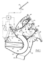
- the device shown in Figure 1 comprises a housing 10 having a cold air intake pipe 12 which is connected to the outlet nozzle 14 of a motor-fan unit (not shown) equipped with a clean blower 16 to send cold air coming from outside the passenger compartment of the vehicle or possibly from an air conditioning unit into the intake pipe 12.
- the intake pipe 12 is connected to an intake and heating circuit comprising a cold air transmission branch 18 and an air heating branch 20 which has a U-shaped configuration and which contains a heat exchanger 22 which is, for example, continuously supplied by the vehicle engine coolant.
- the branch 18 is externally limited by a portion wall 24, while the branch 20 is externally limited by a curved wall portion 26.
- the branch 20 thus constitutes a sort of pocket which internally comprises a wall 28 to define a U-shaped circulation therein.
- the air transmission branch cold 18 extends directly between the two ends of the U-shaped heating branch 20.
- the device further comprises a mixing flap 30 mounted in rotation about an axis 32 and disposed at the junction of the intake pipe 12 and the branches 18 and 20 to vary the distribution, between these two branches, of the flow of air arriving through the intake pipe 12 and, consequently, the temperature of the air leaving the branches 18 and 20.
- the mixing flap 30 is movable between a position A (shown in solid lines) where the air circulates only in the air heating branch 20 and a position B (shown in dashed lines) where the air circulates only through the cold air transmission branch 18, while being able to take any intermediate position.
- The: branches 18 and 20 communicate with each other, at their outlet, by a mixing zone 34 intended to ensure the mixing of the cold air coming from the branch 18 and the hot air coming from the branch 20.
- the flow of cold or heated air thus obtained at the outlet of the intake and heating circuit can penetrate at the inlet 36 of a distribution circuit 38.
- the circuit 38 includes a first outlet pipe 40 limited mainly by two sections of cylindrical walls 42 and 44 and serving at least one demister / defroster mouth 46 to send cold or heated air behind the windshield 69 of the vehicle.
- the distribution of air through the pipe 40 is controlled by a distribution flap 48 mounted in rotation about an axis 50.
- the circuit 38 further comprises a second outlet line 52 mainly limited by two cylindrical wall portions 54 and 56 and serving at least one air vent 58 disposed at the level of the dashboard of the vehicle.
- the circuit 38 further comprises a third outlet pipe 60 which serves an outlet mouth 62 in the lower part of the passenger compartment.
- a second distribution flap 64 rotatably mounted around an axis 65 is provided to control the distribution of air through the outlet pipes 52 and 60.
- the flaps 48 and 64 are synchronized with one another so that they can take five different positions identified respectively by the symbols V (ventilation), BL (bi-level, i.e. temperature stratification), P (feet), DC (defrost-heating) and D (defrost).
- the device as just described above, has a known general structure.
- the device further comprises a defogging pipe 66, also called a "priority defogging" pipe, which is separated from the distribution circuit 38.
- the pipe 66 has an inlet 67 which communicates with the intake circuit for reheating, and more particularly with the mixing zone 34, as well as an outlet 68 opening out behind the windshield 69, near the outlet mouth 46.
- the device further comprises a shutter 70 movable between a position called “priority demister” or “DP” (shown in broken lines in Figure 1) where it closes the inlet 36 of the distribution circuit 38 and a position called “normal use” or “UN” (shown in solid lines in Figure 1) where the flap closes the inlet 67 of the pipe 66.
- DP priority demister
- UN normal use
- the movement of the flap 70 between the two aforementioned positions can be done by means manual, mechanical or electrical controls such as by means of a micromotor (not shown).
- the flow of cold or heated air penetrates through the inlet 36 of the distribution circuit and can be distributed between the various outlet pipes thanks to the two distribution flaps 48 and 64.
- the shutter 70 is operated to bring it into the priority defrost position (DP) and the air flow is brought directly behind the windshield via the pipe 66, without the need to change the setting of the distribution flaps.
- DP priority defrost position
- the device of the invention further comprises an auxiliary cold air intake 72 which is adjacent to the intake pipe 12 and which opens directly into the air heating branch 20, upstream of the heat exchanger 22 There is further provided an auxiliary shutter 74 movable between a closed position (shown in solid lines) where it closes the auxiliary inlet 72 and an open position (shown in broken lines) where it does not close not auxiliary admission 72.
- the auxiliary shutter 72 is movable in synchronism with the shutter 70 so as to be in the open position when the shutter is in the priority demister (DP) position and in the position closing when the shutter is in the normal use position (UN).
- the synchronization of the flaps 70 and 72 can be carried out by conventional mechanical means and the synchronized movement of the two flaps can be carried out manually or else by means of a micromotor.
- the device comprises a probe 76 placed behind the windshield 69 and suitable for detecting the presence or the risk of the appearance of mist or frost behind the windshield.
- This probe is connected to an electronic module 78 capable of controlling the synchronized movement of the flaps 70 and 72 as well as, if necessary, the control of the air blower 16 to bring it to an increased speed.
- the flap 70 closes the inlet 67 of the pipe 66, while the flap 74 closes the auxiliary inlet 72.
- the temperature of the air flow entering the distribution circuit is adjusted by means of the adjustment flap 30 and the distribution of this flow is ensured by the distribution flaps 48 and 64.
- the module 78 acts on the flaps 70 and 74 to bring them into the so-called priority defrost position where the flap 70 closes the inlet 36 of the distribution circuit and the shutter 74 releases the auxiliary intake 72.
- the air is sent into the priority defrost line 66.
- the electronic module is adjusted so that the ventilation speed of the blower 16 is then increased while keeping in memory the initial speed of the blower.
- this circuit comprises a single intake branch 80 interposed between the cold air intake pipe 12 and the area 34 which opens at the same time on the inlet 36 of the distribution circuit 38 and on the inlet 67 of the demister pipe 66.
- the intake branch 80 contains a heat exchanger 82 supplied with a heat transfer fluid (for example the vehicle engine cooling fluid) via a flow control member 84, such as a solenoid valve.
- a heat transfer fluid for example the vehicle engine cooling fluid
- a flow control member 84 such as a solenoid valve.
- the air flow suitable for supplying the circuit 38 or the pipe 64 is adjusted in temperature.
- the device comprises means 86 for controlling the flow control member 84, which are synchronized with the means for controlling the movement of the shutter 70 so that the flow of heat transfer fluid through the heat exchanger is increased, or maintained at the maximum value when the shutter is in the priority demisting position (shown in broken lines in Figure 2).
- the control means 86 are controlled for example by the electronic module 78 which will keep in memory the initial setpoint of the means 86.
- the air intake pipe 12 is connected to an air inlet mouth 88 controlled by an air inlet flap 90 movable between a closed position (shown in solid lines ) of the mouth and an open position (shown in broken lines) of this mouth.
- the mouth 88 is formed through the body of the motor vehicle and allows the device to be supplied with fresh air taken from outside the passenger compartment.
- the device further comprises means 92 for controlling the air inlet flap 90, which are synchronized with the control means 94 for the shutter 70 so that the air inlet flap 90 must be in position. opening (shown in broken lines) when the shutter is in the priority defrost position (shown in broken lines).
- the control means 92 and 94 are also synchronized with the control means 86 of the flow control member 84.
- the member 84 is adjusted so that the heat transfer fluid which passes through the heat exchanger 82 either at an increased temperature, or maintained at the maximum value.
- Figure 4 shows a third embodiment of the device of the invention, which differs from that of Figure 1 by the structure of the intake and heating circuit.
- the intake and heating circuit comprises a cold air transmission branch 18 controlled by a flow control flap 96 and an air heating branch 20 containing a heat exchanger 98 supplied by a heat transfer fluid via a flow control member 100.
- the branches 18 and 20 are connected, on the one hand, to the intake pipe 12 and, on the other hand, to the zone 34 supplying both the inlet 36 of said distribution circuit 38 and the inlet 67 of the priority demister branch 66.
- the device comprises means 102 for controlling the shutter for adjusting the cold air flow 96 and means for controlling 104 the shutter 70.
- control means 104 are advantageously synchronized with the control means 106 of the flow control member 100 so that, in the priority demister position, the temperature of the heat transfer fluid passing through the heat exchanger 98 is increased , or maintained at the maximum value.
- the probe can simply light an indicator light to signal to the driver that he must act on a command suitable for bringing the device to the priority defrost position. It may be a manual control or a control acting on micromotors controlling the various adjustment members of the device.
- the speed of the air blower 16 (Fig. 1) be increased.
- the air blower comprises an electric motor M which can take four different speeds by being supplied directly or through three resistors R1, R2 and R3 of different values which can be selectively switched on by the intermediate of a rheostat 110.
- the probe 76 can then increase or maintain the speed of the motor at the maximum value by acting on a contactor 112 to switch on the motor with a resistor R of appropriate value.
Abstract
Description
L'invention concerne un dispositif de chauffage et de ventilation de l'habitacle d'un véhicule automobile.The invention relates to a device for heating and ventilating the passenger compartment of a motor vehicle.
On connaît déjà des dispositifs de ce genre qui comprennent : une conduite d'admission d'air froid; un circuit d'admission et de réchauffage relié à la conduite d'admission d'air froid et propre à produire un flux d'air froid ou réchauffé; un circuit de distribution relié au circuit d'admission et de réchauffage et comprenant une entrée pour le flux d'air froid ou réchauffé, ainsi que des conduites de sortie d'air alimentées par cette entrée d'air et propres à distribuer, par des moyens de distribution, le flux d'air en différentes zones de l'habitacle, l'une au moins desdites conduites de sortie débouchant derrière le pare-brise pour son désembuage.Devices of this type are already known which include: a cold air intake pipe; an intake and heating circuit connected to the cold air intake pipe and suitable for producing a flow of cold or heated air; a distribution circuit connected to the intake and heating circuit and comprising an inlet for the flow of cold or heated air, as well as air outlet pipes supplied by this air inlet and suitable for distribution, by distribution means, the air flow in different areas of the passenger compartment, at least one of said outlet pipes opening behind the windshield for its demisting.
De tels dispositifs sont utilisés habituellement pour le chauffage et la ventilation - et éventuellement la climatisation - de l'habitacle des véhicules automobiles. Ils servent alors à envoyer de l'air froid ou réchauffé en différentes zones de l'habitacle grâce aux conduites de sortie précitées. Généralement ces dernières sont au nombre de trois et comprennent : la conduite de sortie précitée desservant des bouches de désembuage/dégivrage du pare-brise, une conduite desservant des aérateurs au niveau de la planche de bord et une conduite desservant une bouche en partie inférieure de l'habitacle.Such devices are usually used for heating and ventilating - and possibly air conditioning - the passenger compartment of motor vehicles. They are then used to send cold or heated air to different areas of the passenger compartment using the aforementioned outlet pipes. Generally these are three in number and include: the aforementioned outlet pipe serving defogging / defrosting openings of the windshield, a pipe serving aerators at the dashboard level and a pipe serving a mouth at the bottom of the passenger compartment.
L'air froid provenant de l'extérieur de l'habitacle ou éventuellement d'un groupe de climatisation, est ajusté en température par le circuit d'admission et de réchauffage avant d'être réparti dans l'habitacle.The cold air coming from outside the passenger compartment or possibly from an air conditioning unit, is adjusted in temperature by the intake and heating circuit before being distributed in the passenger compartment.
Par ailleurs, ces dispositifs comprennent, de façon en soi connue, un groupe moto-ventilateur disposé en amont de la conduite d'admission d'air froid pour régler la vitesse du flux d'air qui est envoyé dans l'habitacle.Furthermore, these devices comprise, in a manner known per se, a motor-fan unit disposed upstream of the cold air intake pipe to regulate the speed of the air flow which is sent into the passenger compartment.
La plupart des dispositifs de ce type comprennent des organes de commande manuelle, mécanique ou électrique pour régler la température du flux d'air, sa distribution entre les différentes conduites de sortie et aussi sa vitesse de ventilation.Most devices of this type include manual, mechanical or electrical control members for regulating the temperature of the air flow, its distribution between the various outlet pipes and also its ventilation speed.
Bien que ces dispositifs donnent généralement satisfaction, ils présentent certains inconvénients.Although these devices are generally satisfactory, they have certain drawbacks.
Ainsi, dans le cas où le conducteur constate la présence de buée ou de givre sur le pare-brise du véhicule, il doit manoeuvrer les organes de commande pour modifier à la fois le réglage de la température du flux d'air, son mode de distribution et aussi sa vitesse de ventilation, c'est-à-dire qu'il doit agir quasi simultanément sur trois commandes différentes. Ceci risque de distraire le conducteur de sa conduite, au détriment de la sécurité aggravé par le fait qu'il doit faire front à une mauvaise visibilité.Thus, in the case where the driver notices the presence of mist or frost on the windshield of the vehicle, he must maneuver the control members to modify both the adjustment of the temperature of the air flow, his mode of distribution and also its ventilation speed, that is to say that it must act almost simultaneously on three different controls. This is likely to distract the driver from his driving, to the detriment of safety aggravated by the fact that he must face poor visibility.
Ensuite, lorsque la buée a disparu, il doit à nouveau manoeuvrer les mêmes organes de commande pour retrouver les réglages initiaux correspondant à la situation de confort voulue par le conducteur.Then, when the mist has disappeared, he must again operate the same control members to find the initial settings corresponding to the comfort situation desired by the driver.
Cette opération risque aussi de distraire le conducteur de sa conduite, et cela d'autant plus que les réglages initiaux ne sont pas mémorisables sur les dispositifs à commande manuelle, mécanique ou électrique, ce qui l'obligera à se remémorer les positions initiales des organes de commande.This also risks distracting the driver from driving, especially since the initial settings cannot be memorized on devices with manual, mechanical or electrical control, which will force him to remember the initial positions of the organs control.
L'invention a notamment pour but de remédier aux inconvénients précités.The object of the invention is in particular to remedy the aforementioned drawbacks.
Elle propose, à cet effet, un dispositif de chauffage et de ventilation du type défini en introduction qui, conformément à l'invention,comprend une conduite de désembuage séparée du circuit de distribution, dite conduite de désembuage prioritaire et possédant une entrée communiquant avec le circuit d'admission et de réchauffage et une sortie débouchant derrière le pare-brise, un volet d'obturation déplaçable entre une position dite "désembuage prioritaire" où il obture l'entrée du circuit de distribution et une position dite "utilisation normale" où il obture l'entrée de la conduite de désembuage prioritaire, et des moyens de commande de déplacement du volet entre les deux positions précitées.To this end, it proposes a heating and ventilation device of the type defined in the introduction which, in accordance with the invention, comprises a defog pipe separate from the distribution circuit, called priority defog pipe and having an input communicating with the intake and heating circuit and an outlet opening behind the windshield, a shutter movable between a position called "priority defogging" where it closes the entry of the distribution circuit and a position called "normal use" where it closes the entry of the priority demisting pipe, and means for controlling the movement of the shutter between the two aforementioned positions.
Ainsi, dans la position "utilisation normale", le flux d'air froid ou réchauffé est réparti entre les conduites de sortie du circuit de distribution grâce aux moyens de distribution, tandis que la conduite de désembuage prioritaire est rendue totalement inopérante.Thus, in the "normal use" position, the flow of cold or heated air is distributed between the outlet pipes of the distribution circuit by means of the distribution means, while the priority demister pipe is made completely inoperative.
Dans la position dite "désembuage prioritaire", le flux d'air froid ou réchauffé s'écoule par la conduite de "désembuage prioritaire" pour déboucher derrière le pare-brise du véhicule, tandis que le circuit de distribution est rendu inopérant.In the so-called "priority defogging" position, the flow of cold or heated air flows through the "priority defogging" pipe to open behind the vehicle windshield, while the distribution circuit is rendered inoperative.
Lorsque le volet d'obturation est dans la position de "désembuage prioritaire", les différents réglages du dispositif de chauffage et de ventilation sont conservés, en particulier les réglages assurés par les moyens de distribution.When the shutter is in the "priority defogging" position, the various settings of the heating and ventilation device are retained, in particular the settings provided by the distribution means.
Par conséquent, lorsque le pare-brise est désembué ou dégivré et que le volet d'obturation est ramené dans sa position "utilisation normale", les réglages initiaux du dispositif de chauffage et de ventilation sont retrouvés.Therefore, when the windshield is defogged or defrosted and the shutter is returned to its position "normal use", the initial settings of the heating and ventilation device are found.
Dans le cadre de l'invention, on désigne par le terme "désembuage" toute action propre à envoyer de l'air, de préférence réchauffé, derrière le pare-brise du véhicule pour assurer son désembuage ou son dégivrage, selon le cas.In the context of the invention, the term "demisting" means any action capable of sending air, preferably heated, behind the vehicle windshield to ensure its demisting or defrosting, as the case may be.
Dans une première forme de réalisation de l'invention, le circuit d'admission et de réchauffage comprend une branche de transmission d'air froid interposée entre la conduite d'admission d'air froid et l'entrée du circuit de distribution; une branche de réchauffage d'air interposée entre la conduite d'admission d'air froid et l'entrée du circuit de distribution et contenant un échangeur de chaleur; et un volet de mixage propre à faire varier la répartition du débit d'air entre ces deux branches.In a first embodiment of the invention, the intake and heating circuit comprises a cold air transmission branch interposed between the cold air intake pipe and the inlet of the distribution circuit; an air heating branch interposed between the cold air intake pipe and the inlet of the distribution circuit and containing a heat exchanger; and a mixing shutter capable of varying the distribution of the air flow between these two branches.
L'invention prévoit alors que le dispositif comprend en outre une admission auxiliaire d'air froid qui débouche directement dans la branche de réchauffage d'air en amont de l'échangeur de chaleur, ainsi qu'un volet auxiliaire d'obturation déplaçable entre une position de fermeture et une position d'ouverture de cette admission auxiliaire d'air froid.The invention then provides that the device further comprises an auxiliary cold air intake which opens directly into the air heating branch upstream of the heat exchanger, as well as an auxiliary shutter movable between a closed position and an open position of this auxiliary cold air intake.
De préférence, le volet auxiliaire d'obturation est déplaçable en synchronisme avec le volet d'obturation de manière à être en position d'ouverture lorsque le volet d'obturation est en position de désembuage prioritaire et en position de fermeture lorsque le volet d'obturation est en position d'utilisation normale.Preferably, the auxiliary shutter is movable in synchronism with the shutter so as to be in the open position when the shutter is in the priority demister position and in the closed position when the shutter shutter is in normal use position.
Dans une seconde forme de réalisation de l'invention, le circuit d'admission et de réchauffage comprend une branche d'admission unique interposée entre la conduite de l'admission d'air froid et l'entrée du circuit de distribution, ladite branche d'admission contenant un échangeur de chaleur alimenté par un fluide caloporteur par l'intermédiaire d'un organe de réglage de débit.In a second embodiment of the invention, the intake and heating circuit comprises a branch single intake interposed between the cold air intake pipe and the inlet of the distribution circuit, said intake branch containing a heat exchanger supplied by a heat transfer fluid via an adjusting member of debt.
L'invention prévoit alors que le dispositif comprend des moyens de commande dudit organe de réglage de débit qui sont synchronisés aux moyens de commande de déplacement du volet d'obturation, de sorte que le débit de fluide caloporteur à travers l'échangeur de chaleur soit augmenté lorsque le volet d'obturation est dans la position de désembuage prioritaire.The invention then provides that the device comprises means for controlling said flow-adjusting member which are synchronized with the means for controlling movement of the shutter, so that the flow of heat-transfer fluid through the heat exchanger is increased when the shutter is in the priority demisting position.
Dans une troisième forme de réalisation de l'invention, le circuit d'admission et de réchauffage comprend une branche de transmission d'air froid contrôlée par un volet de réglage de débit, et une branche de réchauffage contenant un échangeur de chaleur alimenté par un fluide caloporteur par l'intermédiaire d'un organe de réglage de débit, les deux branches précitées étant interposées entre, d'une part, la conduite d'admission d'air froid et, d'autre part, l'entrée d'air du circuit de distribution et l'entrée d'air de la conduite de désembuage.In a third embodiment of the invention, the intake and heating circuit comprises a branch for transmitting cold air controlled by a flow control flap, and a heating branch containing a heat exchanger supplied by a heat transfer fluid via a flow control member, the two aforementioned branches being interposed between, on the one hand, the cold air intake pipe and, on the other hand, the air inlet of the distribution circuit and the air inlet of the demister pipe.
Conformément à l'invention, le dispositif comprend en outre des moyens de commande du volet de réglage de débit d'air froid qui sont synchronisés avec les moyens de commande du volet d'obturation de sorte que le volet de réglage de débit d'air froid ferme la branche de transmission d'air froid lorsque le volet d'obturation est dans la position de désembuage prioritaire.According to the invention, the device further comprises means for controlling the shutter for adjusting the cold air flow which are synchronized with the means for controlling the shutter so that the shutter for adjusting the air flow cold closes the cold air transmission branch when the shutter is in the priority demisting position.
Selon une autre caractéristique de l'invention, le dispositif comprend une sonde propre à détecter la présence de buée ou de givre ou le risque d'apparition de buée ou de givre sur le pare-brise.According to another characteristic of the invention, the device comprises a probe capable of detecting the presence of fogging or frost or the risk of fogging or frost on the windshield.
Cette sonde peut informer le conducteur, par exemple au moyen d'un voyant, que de la buée ou du givre se forme ou risque de se déformer derrière le pare-brise. Le conducteur aura alors à appuyer sur une touche commandant automatiquement les moyens de réglage du dispositif dans la position de désembuage prioritaire. En variante, le conducteur pourra avoir à déplacer un levier sur une position désembuage prioritaire.This probe can inform the driver, for example by means of an indicator light, that fogging or frost is forming or may deform behind the windshield. The driver will then have to press a key automatically controlling the means for adjusting the device in the priority demisting position. Alternatively, the driver may have to move a lever to a priority demister position.
Dans une forme de réalisation plus élaborée de l'invention, la sonde est reliée à un module électronique propre à commander le volet d'obturation et éventuellement d'autres moyens de commande synchronisés au volet d'obturation.In a more elaborate embodiment of the invention, the probe is connected to an electronic module suitable for controlling the shutter and possibly other control means synchronized with the shutter.
Ainsi, dans le cas où le dispositif comprend un pulseur d'air propre à envoyer de l'air froid au travers de la conduite d'admission d'air, le module électronique est propre à actionner la vitesse du pulseur à une valeur optimale, par exemple maximale, lorsque le volet d'obturation est dans la position de désembuage prioritaire.Thus, in the case where the device comprises an air blower capable of sending cold air through the air intake pipe, the electronic module is capable of actuating the speed of the blower to an optimal value, for example maximum, when the shutter is in the priority demisting position.
Dans toutes les formes de réalisation de l'invention, la conduite d'admission d'air est avantageusement reliée à une bouche d'entrée d'air contrôlée par un volet d'entrée d'air déplaçable entre une position d'ouverture et une position de fermeture de cette bouche. Selon l'invention, le dispositif comprend en outre des moyens de commande du volet d'entrée d'air qui sont synchronisés aux moyens de commande du volet d'obturation de sorte que le volet d'entrée d'air soit obligatoirement en position d'ouverture lorsque le volet d'obturation est dans la position de dégivrage prioritaire.In all embodiments of the invention, the air intake pipe is advantageously connected to an air inlet mouth controlled by an air inlet flap movable between an open position and a closed position of this mouth. According to the invention, the device further comprises means for controlling the air inlet shutter which are synchronized with the means for controlling the shutter shutter so that the air inlet shutter is necessarily in position d opening when the shutter is in the priority defrost position.
Dans la description qui suit, faite seulement à titre d'exemple, on se réfère aux dessins annexés, sur lesquels:
- la Figure 1 est une vue en coupe d'un dispositif selon l'invention dans la première forme de réalisation précitée;
- la Figure 2 est une vue en coupe d'un dispositif selon l'invention dans la seconde forme de réalisation précitée;
- la Figure 3 est une vue en coupe montrant une installation équipée d'un dispositif selon la Figure 2;
- la Figure 4 est une vue en coupe d'un dispositif selon l'invention conformément à la troisième forme de réalisation précitée; et
- la Figure 5 représente schématiquement un circuit de commande d'un pulseur d'air propre à faire partie d'un dispositif selon l'invention.
- Figure 1 is a sectional view of a device according to the invention in the first embodiment mentioned above;
- Figure 2 is a sectional view of a device according to the invention in the aforementioned second embodiment;
- Figure 3 is a sectional view showing an installation equipped with a device according to Figure 2;
- Figure 4 is a sectional view of a device according to the invention in accordance with the aforementioned third embodiment; and
- Figure 5 schematically shows a control circuit of an air blower suitable for being part of a device according to the invention.
Le dispositif représenté sur la Figure 1 comprend un boîtier 10 comportant une conduite d'admission d'air froid 12 qui est raccordée à l'embout de sortie 14 d'un groupe moto-ventilateur (non représenté) équipé d'un pulseur 16 propre à envoyer dans la conduite d'admission 12 de l'air froid provenant de l'extérieur de l'habitacle du véhicule ou éventuellement d'un groupe de climatisation.The device shown in Figure 1 comprises a
La conduite d'admission 12 est reliée à un circuit d'admission et de réchauffage comprenant une branche de transmission d'air froid 18 et une branche de réchauffage d'air 20 qui présente une configuration en U et qui contient un échangeur de chaleur 22 qui est, par exemple, alimenté en permanence par le fluide de refroidissement du moteur du véhicule. La branche 18 est limitée extérieurement par une portion de paroi 24, tandis que la branche 20 est limitée extérieurement par une portion de paroi incurvée 26. La branche 20 constitue ainsi une sorte de poche qui comprend intérieurement une paroi 28 pour y définir une circulation en U. La branche de transmission d'air froid 18 s'étend de façon directe entre les deux extrémités de la branche de réchauffage 20 en forme de U.The
Le dispositif comprend en outre un volet de mixage 30 monté en rotation autour d'un axe 32 et disposé à la jonction de la conduite d'admission 12 et des branches 18 et 20 pour faire varier la répartition, entre ces deux branches, du débit d'air arrivant par la conduite d'admission 12 et, par conséquent, la température de l'air à la sortie des branches 18 et 20. Le volet de mixage 30 est déplaçable entre une position A (représentée en trait plein) où l'air circule uniquement dans la branche de réchauffage d'air 20 et une position B (représentée en trait interrompu) où l'air circule uniquement à travers la branche de transmission d'air froid 18, tout en pouvant prendre toute position intermédiaire. Le: branches 18 et 20 communiquent entre elles, à leur sortie, par une zone de mixage 34 destinée à assurer le mélange de l'air froid provenant de la branche 18 et de l'air chaud provenant de la branche 20. Le flux d'air froid ou réchauffé ainsi obtenu à la sortie du circuit d'admission et de réchauffage peut pénétrer à l'entrée 36 d'un circuit de distribution 38.The device further comprises a mixing
Le circuit 38 comprend une première conduite de sortie 40 limitée principalement par deux tronçons de parois cylindriques 42 et 44 et desservant au moins une bouche de désembuage/dégivrage 46 pour envoyer de l'air froid ou réchauffé derrière le pare-brise 69 du véhicule. La distribution de l'air à travers la conduite 40 est contrôlée par un volet de distribution 48 monté en rotation autour d'un axe 50.The
Le circuit 38 comprend en outre une seconde conduite de sortie 52 limitée principalement par deux portions de paroi cylindriques 54 et 56 et desservant au moins une bouche d'aération 58 disposée au niveau de la planche de bord du véhicule.The
Le circuit 38 comprend en outre une troisième conduite de sortie 60 qui dessert une bouche de sortie 62 en partie inférieure de l'habitacle.The
Un second volet de distribution 64 monté en rotation autour d'un axe 65 est prévu pour contrôler la distribution de l'air à travers les conduites de sortie 52 et 60. Les volets 48 et 64 sont synchronisés entre eux de manière à pouvoir prendre cinq positions différentes identifiées respectivement par les symboles V (ventilation), BL (bi-level, c'est-à-dire stratification de température), P (pieds), DC (dégivrage-chauffage) et D (dégivrage).A
Le dispositif, tel qu'il vient d'être décrit précédemment est d'une structure générale connue.The device, as just described above, has a known general structure.
Conformément à l'invention, le dispositif comprend en outre une conduite de désembuage 66, encore appelée conduite de "désembuage prioritaire", qui est séparée du circuit de distribution 38. La conduite 66 possède une entrée 67 qui communique avec le circuit d'admission de réchauffage, et plus particulièrement avec la zone de mixage 34, ainsi qu'une sortie 68 débouchant derrière le pare-brise 69, à proximité de la bouche de sortie 46.According to the invention, the device further comprises a
Le dispositif comprend en outre un volet d'obturation 70 déplaçable entre une position dite "désembuage prioritaire" ou "DP" (représenté en trait interrompu sur la Figure 1) où il obture l'entrée 36 du circuit de distribution 38 et une position dite "utilisation normale" ou "UN" (représenté en trait plein sur la Figure 1) où le volet obture l'entrée 67 de la conduite 66. Le déplacement du volet 70 entre les deux positions précitées peut être fait par des moyens de commande manuels, mécaniques, ou électriques tels que par l'intermédiaire d'un micromoteur (non représenté).The device further comprises a
Ainsi, dans la position d'utilisation normale, le flux d'air froid ou réchauffé pénètre par l'entrée 36 du circuit de distribution et peut être réparti entre les différentes conduites de sortie grâce aux deux volets de distribution 48 et 64.Thus, in the normal use position, the flow of cold or heated air penetrates through the
Si le pare-brise 69 doit être désembué ou dégivré, on manoeuvrent le volet 70 pour l'amener dans la position de dégivrage prioritaire (DP) et le flux d'air est amené directement derrière le pare-brise grâce à la conduite 66, sans qu'il soit nécessaire de modifier le réglage des volets de distribution.If the
Le dispositif de l'invention comprend en outre une admission auxiliaire d'air froid 72 qui est adjacente à la conduite d'admission 12 et qui débouche directement dans la branche de réchauffage d'air 20, en amont de l'échangeur de chaleur 22. Il est prévu en outre un volet auxiliaire d'obturation 74 déplaçable entre une position de fermeture (représentée en trait plein) où il obture l'arrivée auxiliaire 72 et une position d'ouverture (représentée en trait interrompu) où il n'obture pas l'admission auxiliaire 72.The device of the invention further comprises an auxiliary
Selon l'invention, le volet auxiliaire d'obturation 72 est déplaçable en synchronisme avec le volet d'obturation 70 de manière à être en position d'ouverture lorsque le volet d'obturation est en position de désembuage prioritaire (DP) et en position de fermeture lorsque le volet d'obturation est en position d'utilisation normale (UN).According to the invention, the
La synchronisation des volets 70 et 72 peut être effectuée par des moyens mécaniques classiques et le déplacement synchronisé des deux volets peut être réalisé manuellement ou bien par l'intermédiaire d'un micromoteur.The synchronization of the
Dans une forme de réalisation élaborée de l'invention, comme représentée à la Figure 1, le dispositif comprend une sonde 76 placée derrière le pare-brise 69 et propre à détecter la présence ou le risque d'apparition de buée ou de givre derrière le pare-brise. Cette sonde est reliée à un module électronique 78 propre à commander le déplacement synchronisé des volets 70 et 72 ainsi que, le cas échéant, la commande du pulseur d'air 16 pour l'amener à une vitesse augmentée.In an elaborate embodiment of the invention, as shown in FIG. 1, the device comprises a
En fonctionnement normal, le volet 70 obture l'entrée 67 de la conduite 66, tandis que le volet 74 obture l'admission auxiliaire 72. La température du flux d'air pénétrant dans le circuit de distribution est ajustée au moyen du volet de réglage 30 et la distribution de ce flux est assurée par les volets de distribution 48 et 64.In normal operation, the
Si la sonde 76 détecte la présence ou le risque d'apparition de buée ou de givre derrière le pare-brise 69, le module 78 agit sur les volets 70 et 74 pour les amener dans la position dite de dégivrage prioritaire où le volet 70 obture l'entrée 36 du circuit de distribution et le volet 74 libère l'admission auxiliaire 72. Ainsi, tout l'air réchauffé est envoyé dans la conduite de dégivrage prioritaire 66. Quelle que soit la position du volet de mixage 30, de l'air pénètre toujours dans la branche de réchauffage 20, grâce à l'admission auxiliaire 72. Avantageusement, le module électronique est réglé de telle façon que la vitesse de ventilation du pulseur 16 soit alors augmentée en gardant en mémoire la vitesse initiale du pulseur.If the
On se réfère maintenant à la forme de réalisation de la Figure 2 qui diffère de celle de la Figure 1, uniquement par ta structure du circuit d'admission et de réchauffage.We now refer to the embodiment of the Figure 2 which differs from that of Figure 1, only by your structure of the intake and heating circuit.
Dans la forme de réalisation de la Figure 2, ce circuit comprend une branche d'admission unique 80 interposée entre la conduite d'admission d'air froid 12 et la zone 34 qui débouche à la fois sur l'entrée 36 du circuit de distribution 38 et sur l'entrée 67 de la conduite de désembuage 66.In the embodiment of Figure 2, this circuit comprises a
La branche d'admission 80 contient un échangeur de chaleur 82 alimenté par un fluide caloporteur (par exemple le fluide de refroidissement du moteur du véhicule) par l'intermédiaire d'un organe de réglage de débit 84, tel qu'une électrovanne. En fonction du réglage de l'organe 84, le flux d'air propre à alimenter le circuit 38 ou la conduite 64 est réglé en température. Selon l'invention, le dispositif comprend des moyens de commande 86 de l'organe de réglage de débit 84, qui sont synchronisés aux moyens de commande du déplacement du volet d'obturation 70 de sorte que le débit de fluide caloporteur à travers l'échangeur de chaleur soit augmenté, ou maintenu à la valeur maximale lorsque le volet d'obturation est dans la position de désembuage prioritaire (représentée en trait interrompu sur la figure 2). Les moyens de commande 86 sont pilotés par exemple par le module électronique 78 qui gardera en mémoire la consigne initiale des moyens 86.The
Comme montré à la Figure 3, la conduite d'admission d'air 12 est reliée à une bouche d'entrée d'air 88 contrôlée par un volet d'entrée d'air 90 déplaçable entre une position de fermeture (représentée en trait plein) de la bouche et une position d'ouverture (représentée en trait interrompu) de cette bouche. La bouche 88 est ménagée au travers de la carrosserie du véhicule automobile et permet d'alimenter le dispositif en air frais prélevé à partir de l'extérieur de l'habitacle.As shown in Figure 3, the
Le dispositif comprend en outre des moyens 92 de commande du volet d'entrée d'air 90, qui sont synchronisés aux moyens de commande 94 du volet d'obturation 70 de sorte que le volet d'entrée d'air 90 soit obligatoirement en position d'ouverture (représentée en trait interrompu) lorsque le volet d'obturation est dans la position de dégivrage prioritaire (représentée en trait interrompu). De préférence, les moyens de commande 92 et 94 sont également synchronisés aux moyens de commande 86 de l'organe de réglage de débit 84. Ainsi, dans la position de dégivrage prioritaire, l'organe 84 est réglé de manière telle que le fluide caloporteur qui traverse l'échangeur de chaleur 82 soit à une température augmentée, ou maintenue à la valeur maximale.The device further comprises means 92 for controlling the
On se réfère maintenant à la Figure 4 qui montre une troisième forme de réalisation du dispositif de l'invention, qui diffère de celle de la Figure 1 par la structure du circuit d'admission et de réchauffage.We now refer to Figure 4 which shows a third embodiment of the device of the invention, which differs from that of Figure 1 by the structure of the intake and heating circuit.
Dans cette forme de réalisation, le circuit d'admission et de réchauffage comprend une branche de transmission d'air froid 18 contrôlée par un volet de réglage de débit 96 et une branche de réchauffage d'air 20 contenant un échangeur de chaleur 98 alimenté par un fluide caloporteur par l'intermédiaire d'un organe de réglage de débit 100.In this embodiment, the intake and heating circuit comprises a cold
Les branches 18 et 20 sont reliées, d'une part, à la conduite d'admission 12 et, d'autre part, à la zone 34 alimentant à la fois l'entrée 36 dudit circuit de distribution 38 et l'entrée 67 de la branche de désembuage prioritaire 66.The
Le dispositif comprend des moyens 102 de commande du volet de réglage de débit d'air froid 96 et des moyens de commande 104 du volet d'obturation 70.The device comprises means 102 for controlling the shutter for adjusting the
Là encore, les moyens de commande 104 sont avantageusement synchronisés avec les moyens de commande 106 de l'organe de réglage de débit 100 pour que, dans la position de désembuage prioritaire, la température du fluide caloporteur traversant l'échangeur de chaleur 98 soit augmentée, ou maintenue à la valeur maximale.Again, the control means 104 are advantageously synchronized with the control means 106 of the
En toutes les formes de réalisation précitées, il est possible d'utiliser, comme décrit à la Figure 1, une sonde placée derrière le pare-brise pour détecter la présence ou le risque d'apparition de buée derrière le pare-brise et commander automatiquement le déplacement du volet d'obturation dans la position de désembuage prioritaire.In all of the above embodiments, it is possible to use, as described in FIG. 1, a probe placed behind the windshield to detect the presence or the risk of the appearance of fogging behind the windshield and to automatically control moving the shutter to the priority demisting position.
Dans des formes de réalisation moins élaborées, la sonde peut simplement allumer un voyant pour signaler au conducteur qu'il doit agir sur une commande propre à amener le dispositif dans la position de dégivrage prioritaire. Il peut s'agir d'une commande manuelle ou encore d'une commande agissant sur des micromoteurs commandant les différents organes de réglage du dispositif.In less elaborate embodiments, the probe can simply light an indicator light to signal to the driver that he must act on a command suitable for bringing the device to the priority defrost position. It may be a manual control or a control acting on micromotors controlling the various adjustment members of the device.
Comme indiqué précédemment, il est préférable que, dans la position de désembuage prioritaire, la vitesse du pulseur d'air 16 (Fig. 1) soit augmentée.As indicated above, it is preferable that, in the priority demisting position, the speed of the air blower 16 (Fig. 1) be increased.
Comme montré à la Figure 5, le pulseur d'air comprend un moteur électrique M pouvant prendre quatre vitesses différentes en étant alimenté directement ou au travers de trois résistances R1, R2 et R3 de valeurs différentes qui peuvent être mises en circuit sélectivement par l'intermédiaire d'un rhéostat 110. La sonde 76 peut alors augmenter ou maintenir à la valeur maximale la vitesse du moteur en agissant sur un contacteur 112 pour mettre le moteur en circuit avec une résistance R de valeur appropriée.As shown in Figure 5, the air blower comprises an electric motor M which can take four different speeds by being supplied directly or through three resistors R1, R2 and R3 of different values which can be selectively switched on by the intermediate of a
Dans la forme de réalisation la plus élaborée du dispositif de l'invention, le module électronique associé à la sonde peut réaliser les opérations suivantes:
- augmenter, ou maintenir à la valeur maximale, la vitesse du pulseur d'air;
- agir sur des motoréducteurs de commande du ou des volets du dispositif pour les actionner;
- agir sur l'électrovanne de l'organe de réglage de débit de l'échangeur de chaleur (lorsqu'il s'agit d'un échangeur du type à robinet) pour augmenter le débit du fluide caloporteur;
- agir sur l'entrée d'air par l'intermédiaire d'une électrovanne, s'il s'agit d'un volet de recyclage.
- increase, or maintain at the maximum value, the speed of the air blower;
- act on geared motors for controlling the flap (s) of the device to activate them;
- act on the solenoid valve of the flow regulator of the heat exchanger (in the case of a valve type exchanger) to increase the flow of the heat transfer fluid;
- act on the air inlet via a solenoid valve, if it is a recycling component.
Claims (8)
Applications Claiming Priority (2)
| Application Number | Priority Date | Filing Date | Title |
|---|---|---|---|
| FR909013568A FR2668429B1 (en) | 1990-10-31 | 1990-10-31 | DEVICE FOR HEATING AND VENTILATING THE INTERIOR OF A MOTOR VEHICLE. |
| FR9013568 | 1990-10-31 |
Publications (2)
| Publication Number | Publication Date |
|---|---|
| EP0484205A1 true EP0484205A1 (en) | 1992-05-06 |
| EP0484205B1 EP0484205B1 (en) | 1995-12-20 |
Family
ID=9401767
Family Applications (1)
| Application Number | Title | Priority Date | Filing Date |
|---|---|---|---|
| EP91402830A Expired - Lifetime EP0484205B1 (en) | 1990-10-31 | 1991-10-23 | Heating and ventilating device for a motor vehicle interior |
Country Status (6)
| Country | Link |
|---|---|
| US (1) | US5173078A (en) |
| EP (1) | EP0484205B1 (en) |
| JP (1) | JPH0687326A (en) |
| DE (1) | DE69115647T2 (en) |
| ES (1) | ES2082948T3 (en) |
| FR (1) | FR2668429B1 (en) |
Cited By (4)
| Publication number | Priority date | Publication date | Assignee | Title |
|---|---|---|---|---|
| FR2728511A1 (en) * | 1994-12-22 | 1996-06-28 | Valeo Thermique Habitacle | Heating and ventilation unit for mounting in motor vehicle |
| EP0756955A2 (en) * | 1995-08-04 | 1997-02-05 | Ford Motor Company | Air-handling system for automotive vehicles |
| AU690051B1 (en) * | 1997-04-01 | 1998-04-09 | Calsonic Corporation | Heater/cooler unit of automotive air conditioning device |
| FR2793738A1 (en) * | 1999-01-16 | 2000-11-24 | Daimler Chrysler Ag | VENTILATION DEVICE FOR VEHICLES |
Families Citing this family (15)
| Publication number | Priority date | Publication date | Assignee | Title |
|---|---|---|---|---|
| EP0663309B1 (en) * | 1993-12-20 | 1995-09-20 | Siemens Aktiengesellschaft | Heating or airconditioning device, in particular for installation in a motorvehicle |
| JP3449071B2 (en) * | 1995-10-26 | 2003-09-22 | 株式会社日本自動車部品総合研究所 | Automotive air conditioners |
| KR100316163B1 (en) * | 1996-07-27 | 2002-12-05 | 한라공조주식회사 | Air conditioning apparatus |
| GB2323158A (en) * | 1997-03-13 | 1998-09-16 | Kl Automotive Products Limited | Air-conditioning vehicles |
| GB2329464B (en) * | 1997-09-20 | 2001-10-10 | Rover Group | An air temperature control and distribution module |
| JP4002681B2 (en) * | 1998-08-10 | 2007-11-07 | カルソニックカンセイ株式会社 | Air conditioner for automobile |
| US6036594A (en) * | 1998-09-08 | 2000-03-14 | Ford Motor Company | Air handling system for automotive vehicles |
| WO2000071484A1 (en) | 1999-05-26 | 2000-11-30 | Ppg Industries Ohio, Inc. | Use of e-glass fibers to reduce plastic shrinkage cracks in concrete |
| FR2805778B1 (en) * | 2000-03-06 | 2002-10-11 | Valeo Climatisation | METHOD FOR AERATION OF A COCKPIT BY SOFT DIFFUSION AND DEVICE FOR IMPLEMENTING IT |
| DE10152998C2 (en) | 2001-10-26 | 2003-12-04 | Preh Elektro Feinmechanik | Sensor unit for the detection of an inner and outer wetting of a pane |
| KR101146430B1 (en) * | 2005-03-29 | 2012-05-18 | 한라공조주식회사 | Rear air conditioner for vehicle |
| ITBO20060281A1 (en) * | 2006-04-13 | 2007-10-14 | Ferrari Spa | AIR CONDITIONING SYSTEM FOR A COTTAGE OF A VEHICLE |
| CN112776839B (en) * | 2021-02-25 | 2022-02-01 | 郑州铁路职业技术学院 | Low-temperature demisting device of railway locomotive |
| CN113173051B (en) * | 2021-04-06 | 2023-01-06 | 侯静霞 | Heat pump air conditioning system for vehicle and control method thereof |
| CN113306451B (en) * | 2021-06-08 | 2023-01-31 | 侯静霞 | Battery pack temperature control device, electric vehicle and control method thereof |
Citations (5)
| Publication number | Priority date | Publication date | Assignee | Title |
|---|---|---|---|---|
| DE1455640A1 (en) * | 1963-02-26 | 1969-02-06 | Daimler Benz Ag | Heating system for vehicles |
| DE2655554A1 (en) * | 1976-12-08 | 1978-06-15 | Audi Nsu Auto Union Ag | Motor vehicle passenger compartment heating system - has blower and heat exchanger with cold air by=pass, and flaps controlling flow through channels |
| US4223754A (en) * | 1977-04-01 | 1980-09-23 | Honda Giken Kogyo Kabushiki Kaisha | Instrument panel device for cars |
| EP0102611A2 (en) * | 1982-09-04 | 1984-03-14 | Bayerische Motoren Werke Aktiengesellschaft, Patentabteilung AJ-3 | Heating and/or air conditioning device for motor vehicles |
| FR2631287A1 (en) * | 1988-05-10 | 1989-11-17 | Valeo | Heating and ventilation device, particularly for motor vehicles |
Family Cites Families (2)
| Publication number | Priority date | Publication date | Assignee | Title |
|---|---|---|---|---|
| DE3339892A1 (en) * | 1983-11-04 | 1985-05-23 | Adam Opel AG, 6090 Rüsselsheim | DEFROSTER SYSTEM FOR A MOTOR VEHICLE |
| FR2650224B1 (en) * | 1989-07-28 | 1994-05-27 | Valeo | HEATING AND VENTILATION DEVICE FOR THE INTERIOR OF A MOTOR VEHICLE |
-
1990
- 1990-10-31 FR FR909013568A patent/FR2668429B1/en not_active Expired - Fee Related
-
1991
- 1991-10-23 EP EP91402830A patent/EP0484205B1/en not_active Expired - Lifetime
- 1991-10-23 ES ES91402830T patent/ES2082948T3/en not_active Expired - Lifetime
- 1991-10-23 DE DE69115647T patent/DE69115647T2/en not_active Expired - Fee Related
- 1991-10-29 US US07/783,916 patent/US5173078A/en not_active Expired - Fee Related
- 1991-10-30 JP JP3310125A patent/JPH0687326A/en active Pending
Patent Citations (5)
| Publication number | Priority date | Publication date | Assignee | Title |
|---|---|---|---|---|
| DE1455640A1 (en) * | 1963-02-26 | 1969-02-06 | Daimler Benz Ag | Heating system for vehicles |
| DE2655554A1 (en) * | 1976-12-08 | 1978-06-15 | Audi Nsu Auto Union Ag | Motor vehicle passenger compartment heating system - has blower and heat exchanger with cold air by=pass, and flaps controlling flow through channels |
| US4223754A (en) * | 1977-04-01 | 1980-09-23 | Honda Giken Kogyo Kabushiki Kaisha | Instrument panel device for cars |
| EP0102611A2 (en) * | 1982-09-04 | 1984-03-14 | Bayerische Motoren Werke Aktiengesellschaft, Patentabteilung AJ-3 | Heating and/or air conditioning device for motor vehicles |
| FR2631287A1 (en) * | 1988-05-10 | 1989-11-17 | Valeo | Heating and ventilation device, particularly for motor vehicles |
Cited By (5)
| Publication number | Priority date | Publication date | Assignee | Title |
|---|---|---|---|---|
| FR2728511A1 (en) * | 1994-12-22 | 1996-06-28 | Valeo Thermique Habitacle | Heating and ventilation unit for mounting in motor vehicle |
| EP0756955A2 (en) * | 1995-08-04 | 1997-02-05 | Ford Motor Company | Air-handling system for automotive vehicles |
| EP0756955B1 (en) * | 1995-08-04 | 2003-11-05 | Ford Motor Company | Air-handling system for automotive vehicles |
| AU690051B1 (en) * | 1997-04-01 | 1998-04-09 | Calsonic Corporation | Heater/cooler unit of automotive air conditioning device |
| FR2793738A1 (en) * | 1999-01-16 | 2000-11-24 | Daimler Chrysler Ag | VENTILATION DEVICE FOR VEHICLES |
Also Published As
| Publication number | Publication date |
|---|---|
| DE69115647T2 (en) | 1996-05-15 |
| DE69115647D1 (en) | 1996-02-01 |
| FR2668429B1 (en) | 1994-09-30 |
| FR2668429A1 (en) | 1992-04-30 |
| JPH0687326A (en) | 1994-03-29 |
| US5173078A (en) | 1992-12-22 |
| ES2082948T3 (en) | 1996-04-01 |
| EP0484205B1 (en) | 1995-12-20 |
Similar Documents
| Publication | Publication Date | Title |
|---|---|---|
| EP0484205B1 (en) | Heating and ventilating device for a motor vehicle interior | |
| US7222667B2 (en) | Vehicular air-conditioning apparatus | |
| FR2706816A1 (en) | Apparatus for heating-ventilating and/or air-conditioning the passenger compartment of a motor vehicle, especially an electric vehicle | |
| EP0595699A1 (en) | Cooling and airconditioning device for an electric vehicle | |
| EP1658195A1 (en) | Motor vehicle seat ventilation module | |
| FR2659907A1 (en) | HEATING AND VENTILATION DEVICE WITH SEPARATE MEANS OF TEMPERATURE ADJUSTMENT IN THE PLACES BEFORE THE COCKPIT OF A MOTOR VEHICLE. | |
| EP2889168B1 (en) | Heating, ventilation and/or air conditioning device | |
| WO2002032705A1 (en) | Heating-air conditioning installation for vehicles | |
| EP0600778A1 (en) | Heating, ventilation and/or air conditioning device for a motor vehicle interior | |
| FR2742383A1 (en) | Heater or air-conditioner for passenger space of motor vehicle | |
| EP0289405A1 (en) | Heating and ventilation apparatus, especially for the passenger compartment of a motor vehicle | |
| EP0246948B1 (en) | Heating and ventilating apparatus for a motor vehicle | |
| EP2528758B1 (en) | Heating, ventilation and/or air conditioning system, in particular for an electric automobile vehicle | |
| FR2629022A1 (en) | HEATING AND / OR AIR CONDITIONING INSTALLATION FOR MOTOR VEHICLE | |
| EP0645267A1 (en) | Air conditioning device for motor vehicle | |
| EP1165335A1 (en) | Air conditioning installation with separate treatment for rear section of passenger compartment | |
| EP0961698B1 (en) | Heating/air-conditioning device integrated in a motor vehicle instrument panel | |
| FR2720695A1 (en) | Device for heating and / or air conditioning of the passenger compartment of a vehicle. | |
| EP0600779A1 (en) | Device for heating, ventilating and/or air conditioning the interior of a motor vehicle | |
| FR2783465A1 (en) | Vehicle heating/air conditioning system integrated into the vehicles instrument panel. | |
| EP3983245B1 (en) | Control device, and associated heating and/or ventilation and/or air conditioning installation, motor vehicle and temperature management method | |
| FR2687956A1 (en) | APPARATUS FOR THE AIR CONDITIONING OF A MOTOR VEHICLE WITH AUTOMATIC ADJUSTMENT OF THE DISEMBLING / DEFROSTING OF THE GLASSES OF THE VEHICLE. | |
| EP0835773A1 (en) | Heating and/or air conditioning system for a vehicle with separate control for the left and right side of the interior | |
| EP1484206B1 (en) | A heating/air-conditioning device suitable for housing in a vehicle flat instrument panel | |
| FR2664540A1 (en) | Air-conditioning plant for motor vehicle |
Legal Events
| Date | Code | Title | Description |
|---|---|---|---|
| PUAI | Public reference made under article 153(3) epc to a published international application that has entered the european phase |
Free format text: ORIGINAL CODE: 0009012 |
|
| AK | Designated contracting states |
Kind code of ref document: A1 Designated state(s): DE ES GB IT SE |
|
| 17P | Request for examination filed |
Effective date: 19920612 |
|
| 17Q | First examination report despatched |
Effective date: 19930825 |
|
| GRAA | (expected) grant |
Free format text: ORIGINAL CODE: 0009210 |
|
| AK | Designated contracting states |
Kind code of ref document: B1 Designated state(s): DE ES GB IT SE |
|
| ITF | It: translation for a ep patent filed |
Owner name: SOCIETA' ITALIANA BREVETTI S.P.A. |
|
| REF | Corresponds to: |
Ref document number: 69115647 Country of ref document: DE Date of ref document: 19960201 |
|
| GBT | Gb: translation of ep patent filed (gb section 77(6)(a)/1977) |
Effective date: 19960217 |
|
| REG | Reference to a national code |
Ref country code: ES Ref legal event code: FG2A Ref document number: 2082948 Country of ref document: ES Kind code of ref document: T3 |
|
| PLBE | No opposition filed within time limit |
Free format text: ORIGINAL CODE: 0009261 |
|
| STAA | Information on the status of an ep patent application or granted ep patent |
Free format text: STATUS: NO OPPOSITION FILED WITHIN TIME LIMIT |
|
| 26N | No opposition filed | ||
| PGFP | Annual fee paid to national office [announced via postgrant information from national office to epo] |
Ref country code: SE Payment date: 20000919 Year of fee payment: 10 |
|
| PGFP | Annual fee paid to national office [announced via postgrant information from national office to epo] |
Ref country code: DE Payment date: 20001014 Year of fee payment: 10 |
|
| PGFP | Annual fee paid to national office [announced via postgrant information from national office to epo] |
Ref country code: ES Payment date: 20001016 Year of fee payment: 10 |
|
| PGFP | Annual fee paid to national office [announced via postgrant information from national office to epo] |
Ref country code: GB Payment date: 20001017 Year of fee payment: 10 |
|
| PG25 | Lapsed in a contracting state [announced via postgrant information from national office to epo] |
Ref country code: GB Free format text: LAPSE BECAUSE OF NON-PAYMENT OF DUE FEES Effective date: 20011023 |
|
| PG25 | Lapsed in a contracting state [announced via postgrant information from national office to epo] |
Ref country code: SE Free format text: LAPSE BECAUSE OF NON-PAYMENT OF DUE FEES Effective date: 20011024 Ref country code: ES Free format text: LAPSE BECAUSE OF NON-PAYMENT OF DUE FEES Effective date: 20011024 |
|
| REG | Reference to a national code |
Ref country code: GB Ref legal event code: IF02 |
|
| EUG | Se: european patent has lapsed |
Ref document number: 91402830.3 |
|
| GBPC | Gb: european patent ceased through non-payment of renewal fee |
Effective date: 20011023 |
|
| PG25 | Lapsed in a contracting state [announced via postgrant information from national office to epo] |
Ref country code: DE Free format text: LAPSE BECAUSE OF NON-PAYMENT OF DUE FEES Effective date: 20020702 |
|
| REG | Reference to a national code |
Ref country code: ES Ref legal event code: FD2A Effective date: 20021113 |
|
| PG25 | Lapsed in a contracting state [announced via postgrant information from national office to epo] |
Ref country code: IT Free format text: LAPSE BECAUSE OF NON-PAYMENT OF DUE FEES Effective date: 20051023 |