EP0537874B1 - Dispositif de freinage pour un véhicule non-guidé - Google Patents
Dispositif de freinage pour un véhicule non-guidé Download PDFInfo
- Publication number
- EP0537874B1 EP0537874B1 EP92250299A EP92250299A EP0537874B1 EP 0537874 B1 EP0537874 B1 EP 0537874B1 EP 92250299 A EP92250299 A EP 92250299A EP 92250299 A EP92250299 A EP 92250299A EP 0537874 B1 EP0537874 B1 EP 0537874B1
- Authority
- EP
- European Patent Office
- Prior art keywords
- brake
- vehicle
- braking
- force
- speed
- Prior art date
- Legal status (The legal status is an assumption and is not a legal conclusion. Google has not performed a legal analysis and makes no representation as to the accuracy of the status listed.)
- Revoked
Links
Images

Classifications
-
- B—PERFORMING OPERATIONS; TRANSPORTING
- B60—VEHICLES IN GENERAL
- B60L—PROPULSION OF ELECTRICALLY-PROPELLED VEHICLES; SUPPLYING ELECTRIC POWER FOR AUXILIARY EQUIPMENT OF ELECTRICALLY-PROPELLED VEHICLES; ELECTRODYNAMIC BRAKE SYSTEMS FOR VEHICLES IN GENERAL; MAGNETIC SUSPENSION OR LEVITATION FOR VEHICLES; MONITORING OPERATING VARIABLES OF ELECTRICALLY-PROPELLED VEHICLES; ELECTRIC SAFETY DEVICES FOR ELECTRICALLY-PROPELLED VEHICLES
- B60L7/00—Electrodynamic brake systems for vehicles in general
- B60L7/28—Eddy-current braking
-
- B—PERFORMING OPERATIONS; TRANSPORTING
- B60—VEHICLES IN GENERAL
- B60L—PROPULSION OF ELECTRICALLY-PROPELLED VEHICLES; SUPPLYING ELECTRIC POWER FOR AUXILIARY EQUIPMENT OF ELECTRICALLY-PROPELLED VEHICLES; ELECTRODYNAMIC BRAKE SYSTEMS FOR VEHICLES IN GENERAL; MAGNETIC SUSPENSION OR LEVITATION FOR VEHICLES; MONITORING OPERATING VARIABLES OF ELECTRICALLY-PROPELLED VEHICLES; ELECTRIC SAFETY DEVICES FOR ELECTRICALLY-PROPELLED VEHICLES
- B60L1/00—Supplying electric power to auxiliary equipment of vehicles
- B60L1/003—Supplying electric power to auxiliary equipment of vehicles to auxiliary motors, e.g. for pumps, compressors
-
- B—PERFORMING OPERATIONS; TRANSPORTING
- B60—VEHICLES IN GENERAL
- B60L—PROPULSION OF ELECTRICALLY-PROPELLED VEHICLES; SUPPLYING ELECTRIC POWER FOR AUXILIARY EQUIPMENT OF ELECTRICALLY-PROPELLED VEHICLES; ELECTRODYNAMIC BRAKE SYSTEMS FOR VEHICLES IN GENERAL; MAGNETIC SUSPENSION OR LEVITATION FOR VEHICLES; MONITORING OPERATING VARIABLES OF ELECTRICALLY-PROPELLED VEHICLES; ELECTRIC SAFETY DEVICES FOR ELECTRICALLY-PROPELLED VEHICLES
- B60L1/00—Supplying electric power to auxiliary equipment of vehicles
- B60L1/02—Supplying electric power to auxiliary equipment of vehicles to electric heating circuits
-
- B—PERFORMING OPERATIONS; TRANSPORTING
- B60—VEHICLES IN GENERAL
- B60L—PROPULSION OF ELECTRICALLY-PROPELLED VEHICLES; SUPPLYING ELECTRIC POWER FOR AUXILIARY EQUIPMENT OF ELECTRICALLY-PROPELLED VEHICLES; ELECTRODYNAMIC BRAKE SYSTEMS FOR VEHICLES IN GENERAL; MAGNETIC SUSPENSION OR LEVITATION FOR VEHICLES; MONITORING OPERATING VARIABLES OF ELECTRICALLY-PROPELLED VEHICLES; ELECTRIC SAFETY DEVICES FOR ELECTRICALLY-PROPELLED VEHICLES
- B60L50/00—Electric propulsion with power supplied within the vehicle
- B60L50/30—Electric propulsion with power supplied within the vehicle using propulsion power stored mechanically, e.g. in fly-wheels
-
- B—PERFORMING OPERATIONS; TRANSPORTING
- B60—VEHICLES IN GENERAL
- B60L—PROPULSION OF ELECTRICALLY-PROPELLED VEHICLES; SUPPLYING ELECTRIC POWER FOR AUXILIARY EQUIPMENT OF ELECTRICALLY-PROPELLED VEHICLES; ELECTRODYNAMIC BRAKE SYSTEMS FOR VEHICLES IN GENERAL; MAGNETIC SUSPENSION OR LEVITATION FOR VEHICLES; MONITORING OPERATING VARIABLES OF ELECTRICALLY-PROPELLED VEHICLES; ELECTRIC SAFETY DEVICES FOR ELECTRICALLY-PROPELLED VEHICLES
- B60L50/00—Electric propulsion with power supplied within the vehicle
- B60L50/50—Electric propulsion with power supplied within the vehicle using propulsion power supplied by batteries or fuel cells
- B60L50/60—Electric propulsion with power supplied within the vehicle using propulsion power supplied by batteries or fuel cells using power supplied by batteries
- B60L50/61—Electric propulsion with power supplied within the vehicle using propulsion power supplied by batteries or fuel cells using power supplied by batteries by batteries charged by engine-driven generators, e.g. series hybrid electric vehicles
-
- B—PERFORMING OPERATIONS; TRANSPORTING
- B60—VEHICLES IN GENERAL
- B60L—PROPULSION OF ELECTRICALLY-PROPELLED VEHICLES; SUPPLYING ELECTRIC POWER FOR AUXILIARY EQUIPMENT OF ELECTRICALLY-PROPELLED VEHICLES; ELECTRODYNAMIC BRAKE SYSTEMS FOR VEHICLES IN GENERAL; MAGNETIC SUSPENSION OR LEVITATION FOR VEHICLES; MONITORING OPERATING VARIABLES OF ELECTRICALLY-PROPELLED VEHICLES; ELECTRIC SAFETY DEVICES FOR ELECTRICALLY-PROPELLED VEHICLES
- B60L58/00—Methods or circuit arrangements for monitoring or controlling batteries or fuel cells, specially adapted for electric vehicles
- B60L58/10—Methods or circuit arrangements for monitoring or controlling batteries or fuel cells, specially adapted for electric vehicles for monitoring or controlling batteries
- B60L58/12—Methods or circuit arrangements for monitoring or controlling batteries or fuel cells, specially adapted for electric vehicles for monitoring or controlling batteries responding to state of charge [SoC]
-
- B—PERFORMING OPERATIONS; TRANSPORTING
- B60—VEHICLES IN GENERAL
- B60L—PROPULSION OF ELECTRICALLY-PROPELLED VEHICLES; SUPPLYING ELECTRIC POWER FOR AUXILIARY EQUIPMENT OF ELECTRICALLY-PROPELLED VEHICLES; ELECTRODYNAMIC BRAKE SYSTEMS FOR VEHICLES IN GENERAL; MAGNETIC SUSPENSION OR LEVITATION FOR VEHICLES; MONITORING OPERATING VARIABLES OF ELECTRICALLY-PROPELLED VEHICLES; ELECTRIC SAFETY DEVICES FOR ELECTRICALLY-PROPELLED VEHICLES
- B60L7/00—Electrodynamic brake systems for vehicles in general
- B60L7/10—Dynamic electric regenerative braking
- B60L7/18—Controlling the braking effect
-
- B—PERFORMING OPERATIONS; TRANSPORTING
- B60—VEHICLES IN GENERAL
- B60L—PROPULSION OF ELECTRICALLY-PROPELLED VEHICLES; SUPPLYING ELECTRIC POWER FOR AUXILIARY EQUIPMENT OF ELECTRICALLY-PROPELLED VEHICLES; ELECTRODYNAMIC BRAKE SYSTEMS FOR VEHICLES IN GENERAL; MAGNETIC SUSPENSION OR LEVITATION FOR VEHICLES; MONITORING OPERATING VARIABLES OF ELECTRICALLY-PROPELLED VEHICLES; ELECTRIC SAFETY DEVICES FOR ELECTRICALLY-PROPELLED VEHICLES
- B60L7/00—Electrodynamic brake systems for vehicles in general
- B60L7/24—Electrodynamic brake systems for vehicles in general with additional mechanical or electromagnetic braking
- B60L7/26—Controlling the braking effect
-
- B—PERFORMING OPERATIONS; TRANSPORTING
- B60—VEHICLES IN GENERAL
- B60L—PROPULSION OF ELECTRICALLY-PROPELLED VEHICLES; SUPPLYING ELECTRIC POWER FOR AUXILIARY EQUIPMENT OF ELECTRICALLY-PROPELLED VEHICLES; ELECTRODYNAMIC BRAKE SYSTEMS FOR VEHICLES IN GENERAL; MAGNETIC SUSPENSION OR LEVITATION FOR VEHICLES; MONITORING OPERATING VARIABLES OF ELECTRICALLY-PROPELLED VEHICLES; ELECTRIC SAFETY DEVICES FOR ELECTRICALLY-PROPELLED VEHICLES
- B60L2200/00—Type of vehicles
- B60L2200/26—Rail vehicles
-
- B—PERFORMING OPERATIONS; TRANSPORTING
- B60—VEHICLES IN GENERAL
- B60L—PROPULSION OF ELECTRICALLY-PROPELLED VEHICLES; SUPPLYING ELECTRIC POWER FOR AUXILIARY EQUIPMENT OF ELECTRICALLY-PROPELLED VEHICLES; ELECTRODYNAMIC BRAKE SYSTEMS FOR VEHICLES IN GENERAL; MAGNETIC SUSPENSION OR LEVITATION FOR VEHICLES; MONITORING OPERATING VARIABLES OF ELECTRICALLY-PROPELLED VEHICLES; ELECTRIC SAFETY DEVICES FOR ELECTRICALLY-PROPELLED VEHICLES
- B60L2260/00—Operating Modes
- B60L2260/20—Drive modes; Transition between modes
- B60L2260/28—Four wheel or all wheel drive
-
- Y—GENERAL TAGGING OF NEW TECHNOLOGICAL DEVELOPMENTS; GENERAL TAGGING OF CROSS-SECTIONAL TECHNOLOGIES SPANNING OVER SEVERAL SECTIONS OF THE IPC; TECHNICAL SUBJECTS COVERED BY FORMER USPC CROSS-REFERENCE ART COLLECTIONS [XRACs] AND DIGESTS
- Y02—TECHNOLOGIES OR APPLICATIONS FOR MITIGATION OR ADAPTATION AGAINST CLIMATE CHANGE
- Y02T—CLIMATE CHANGE MITIGATION TECHNOLOGIES RELATED TO TRANSPORTATION
- Y02T10/00—Road transport of goods or passengers
- Y02T10/60—Other road transportation technologies with climate change mitigation effect
- Y02T10/62—Hybrid vehicles
-
- Y—GENERAL TAGGING OF NEW TECHNOLOGICAL DEVELOPMENTS; GENERAL TAGGING OF CROSS-SECTIONAL TECHNOLOGIES SPANNING OVER SEVERAL SECTIONS OF THE IPC; TECHNICAL SUBJECTS COVERED BY FORMER USPC CROSS-REFERENCE ART COLLECTIONS [XRACs] AND DIGESTS
- Y02—TECHNOLOGIES OR APPLICATIONS FOR MITIGATION OR ADAPTATION AGAINST CLIMATE CHANGE
- Y02T—CLIMATE CHANGE MITIGATION TECHNOLOGIES RELATED TO TRANSPORTATION
- Y02T10/00—Road transport of goods or passengers
- Y02T10/60—Other road transportation technologies with climate change mitigation effect
- Y02T10/70—Energy storage systems for electromobility, e.g. batteries
Definitions
- the invention relates to a braking device for a non-track-bound vehicle, in particular for a vehicle with at least one electric motor, which drives the vehicle and is powered by an electrical generator and / or an electrical store via a power electronics unit, with a control, and with a brake system operated by means of a brake pedal according to the preamble of patent claim 1.
- Motor vehicles that is to say passenger cars, trucks, buses and the like, are usually equipped with an internal combustion engine.
- motor vehicles with an electric motor have also been developed, including so-called vehicles with a solar drive, i.e. Photocells that supply the electricity for the drive electric motor.
- a drive concept has recently been proposed in which an internal combustion engine is coupled to an electrical generator which feeds electric motors which are coupled directly to the driven wheels of the vehicle. If you also see a memory, e.g. a flywheel, as a mechanical energy store, so one can call up the acceleration power to be made available at short notice from the energy store while the internal combustion engine is operating at a more or less constant speed in order to continuously feed energy into the flywheel energy store.
- a memory e.g. a flywheel
- Vehicles with an electric motor drive have a fundamentally different driving behavior than vehicles with an internal combustion engine drive. While only a very small speed range with a relatively high torque is available in internal combustion engines, the change in torque in the electric motor is less dependent on the speed.
- a vehicle with an internal combustion engine drive In a vehicle with an internal combustion engine drive, the speed of the internal combustion engine decreases to a low value with a minimal fuel supply, or a braking torque corresponding to the mechanical friction of the internal combustion engine is generated when the fuel supply is completely switched off.
- greater braking forces are required, which are applied via a brake pedal and possibly amplified via a brake booster.
- the energy on the brake discs is largely converted into heat by friction.
- rail vehicles with an electric motor drive it is customary to operate the electric motor as a generator when braking, in order to use the electrical energy then induced as heating energy via resistors.
- non-track-bound vehicles which are equipped with an electric motor drive, one can also think of such useful braking.
- the possibilities of an electric motor drive are still there not exhausted, since control electronics and power electronics are usually present in a modern electromotive drive, which permit use of the energy generated during the braking process to go beyond the use of braking energy as heating energy.
- DE 37 25 620 A1 discloses a drive and brake concept for a non-track-bound vehicle with an internal combustion engine and a mechanical-hydraulic brake system in which the internal combustion engine drives an electric generator.
- the electrical energy generated in this way is fed via an electronic control with power electronics to four electric motors, each of which is individually connected to a drive wheel of the vehicle in terms of drive technology.
- the vehicle is also equipped with a flywheel accumulator that functions as an electric motor or generator as required.
- the electronic control of the vehicle distributes the required braking force to the mechanical-hydraulic brake system and the electric drive motors, which then work as electrical generators, and feeds the generated electricity to the flywheel storage.
- the stored energy can be called up by the control system for re-feeding into the electric motors.
- the electric motors in this vehicle are only used when the flywheel storage is not yet fully charged and it is also a "normal braking"; this means that only the mechanical-hydraulic brake system is used in cases of high braking forces.
- the phenomenon occurs that the vehicle suddenly comes to a standstill in the last phase of the braking process when stopping, particularly when this occurs with a considerable deceleration. This is often perceived by drivers and passengers as uncomfortable.
- the invention is based on the object of specifying a braking device for a vehicle of the generic type which, with regard to the most efficient use of given components of the vehicle, improves driving comfort without appreciable additional effort without impairing safety when braking.
- a vehicle with the braking device is preferably not only equipped with a mechanical-hydraulic braking system but at the same time also with an electrically operated braking system, which in turn can consist of different systems.
- the electric brake system is designed at least in such a way that the electric motors are switched from the electronic control for braking into generator operation and in this way generate a braking torque.
- the electrical energy generated in this way can be stored, for example, in an energy store (for example flywheel storage or accumulator), used to drive auxiliary units (for example air conditioning system, fan) or for heating purposes.
- the electric brake system can also include an eddy current brake, for example.
- the performance of the various braking systems can be designed for the maximum required braking force or only for a fraction of this maximum braking force. At least the mechanical-hydraulic brake system will always be able to apply the maximum required braking force alone for safety reasons.
- an electric eddy current braking system is preferably put into operation before or parallel to the activation of the mechanical-hydraulic braking system, which braking system is fed by the electric motors working in generator operation becomes.
- This variant therefore offers a total of three options for braking the vehicle: 1.Brake down by switching the drive electric motor as a generator, 2.Brake down by a (conventional) mechanical-hydraulic brake system, and 3 the electric eddy current brake is supplied with current during a braking operation.
- the feeding of the electric eddy current brake during the braking process is particularly favorable here because the electric current required to feed the eddy current brake is supplied by the electric motor which then functions as a generator.
- the electric eddy current brake also has the considerable advantage that a trailer coupled to the vehicle can be effectively braked without having to do so exclusively by means of mechanical braking, as was previously the case.
- an electronically controlled braking system that delivers up to 100% of the maximum required braking torque, but also one with smaller braking forces, as explained in more detail below, can be designed in accordance with the invention in such a way that it allows the vehicle to be stopped completely without jerking Driver would have to make a special effort.
- the invention provides that the electronic control detects the vehicle speed with the brake pedal travel kept approximately constant, shortly before the vehicle speed reaches "0", e.g. at 1 ... 3 km / h, the braking force is reduced to a minimum value (on level roads, for example, the value "0") and that when the vehicle speed is "0", the braking force is suddenly increased to a value at which the Vehicle can be kept at a standstill.
- the electronic control ensures a practically completely jerk-free braking without the driver having to be particularly sensitive when operating the brake pedal.
- the jerky stopping of a vehicle occurs due to the transition from sliding friction to static friction on the brake discs or brake pads. Due to the continuous reduction of the braking force, the sliding friction is practically zero when the vehicle stops.
- the brakes are applied or applied again by a sudden increase in the braking force, so that the vehicle cannot roll away.
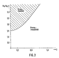
- the braking force distribution on the front axle and rear axle corresponds to a non-linear function to ensure braking stability.
- This known relationship is shown in FIG. 3.
- the deceleration z is calculated from the relationship where x is the deceleration of the vehicle and g is the acceleration due to gravity.
- the Braking stability, the braking force B v applied to the wheels of the front axle can be relatively increased at higher values of z compared to the braking force B h applied to the wheels of the rear axle.
- the hatched area at the top left in FIG. 3 is the area in which braking stability is guaranteed, provided the road surface is dry. In the remaining area there is brake instability.
- the braking force or the braking torque for the front or the rear axle is distributed by an electronic control, preferably by the electronic control already present in the vehicle provided with an electric motor drive, depending on the braking z becomes.
- the range in which the braking force is distributed to the wheels of the front axle or that of the rear axle ranges from approximately 1.5 to approximately 3.5.
- the braking force can thus be distributed in such a way that the required braking stability according to FIG. 3 is achieved in any case.
- full braking with the correct braking force distribution, an optimally short braking distance can be achieved without the risk that the vehicle will break out because, for example, the braking force distribution does not correspond to the conditions defined in FIG. 3.
- VGE internal combustion engine generator unit
- An electronic controller 12 equipped with a microprocessor receives speed signals from the electric motors 6a ... 6d and also receives further signals from sensors (not shown here) which are characteristic of the operation of the VGE 10, the state of the electric motors 6a ... 6d Position of a driving lever, not shown, and the like. Depending on the position of the drive lever, the VGE 10 provides a certain electrical power, which via the power electronics unit 8 in accordance with the electronic control 12 is given to the electric motors 6a ... 6d.
- An accumulator 11 is available as an additional energy source, from which energy for accelerating the vehicle 2 can be taken as for other purposes. It is also possible to store energy in the accumulator 11. For this purpose, the state of charge of the rechargeable battery 11 is detected by a sensor and signaled to the controller 12, which possibly causes the VGE 10 to feed electrical energy into the rechargeable battery 11 via the power electronics unit 8.
- the VGE 10 has an internal combustion engine, e.g. an Otto engine, and an electrical generator with preferably electronic commutation.
- a brake pedal 14 which is actuated by the foot of the driver of the vehicle 2, is schematically indicated on the right in FIG. 1.
- the pedal travel of the pedal 14 is detected by a potentiometer 16 functioning as a travel sensor, and a corresponding signal is supplied by the potentiometer 16 to the controller 12.
- the brake pedal 15 is coupled to a brake cylinder / brake booster unit 20 which, in a manner known per se, transmits braking force via hydraulic lines B to brake cylinders (not shown here) on brakes on the four wheels 4a ... 4d.
- the controller 12 then causes the electric motors 6a ... 6d to be switched to generator operation. As a result, the electric motors 6a ... 6d oppose the rotational movement of the wheels 4a ... 4d coupled directly to them. Electrical energy is now supplied via lines L1 ... L4 from the electric motors 4a ... 4d to the power electronics unit 8, from where the energy is distributed according to the invention.
- the electrical energy generated during braking operation can be stored in the accumulator 11, if its state of charge allows it.
- the useful energy obtained is optionally introduced into electrical resistance elements in which it is converted into thermal energy for heating purposes, it can be supplied to auxiliary units, for example a fan, a compressor for an air conditioning system or the like, or the electrical energy obtained from the braking process can be fed directly to electrical consumers, e.g. the vehicle's lighting system.
- auxiliary units for example a fan, a compressor for an air conditioning system or the like
- the electrical energy obtained from the braking process can be fed directly to electrical consumers, e.g. the vehicle's lighting system.
- the distribution of the energy is basically done by the controller 12.
- the controller 12 is connected to the various components and assemblies via signal lines, which are shown in broken lines in FIG. 1.
- the signal lines to the rear electric motors 6c and 6d are not shown.
- eddy current brakes 18a ... 18d each of which is coupled to a drive shaft of an electric motor 6a ... 6d.
- the controller 12 can determine the instantaneous longitudinal deceleration of the vehicle from the speeds of the electric motors 6a ... 6d. From this in turn, the controller 12 can calculate a braking force distribution for the front electric motors 6a and 6b and the front eddy current brakes 18a and 18b as well as for the rear electric motors 6c and 6d and the rear eddy current brakes 18c and 18d. This enables an optimal braking effect to be achieved, ie the shortest braking distance.
- the braking device comprises two elements, namely an electric or electronic brake pedal displacement sensor 16 e.g. in the form of a potentiometer and also the usual mechanics to provide the required hydraulic energy for the usual disc brakes or drum brakes on the individual vehicle wheels 4a ... 4d via a brake booster and a brake cylinder.
- an electric or electronic brake pedal displacement sensor 16 e.g. in the form of a potentiometer
- the usual mechanics to provide the required hydraulic energy for the usual disc brakes or drum brakes on the individual vehicle wheels 4a ... 4d via a brake booster and a brake cylinder.
- the mode of operation of the electronically controlled braking device for stopping the vehicle smoothly is described below with reference to FIG. 2. If, for example, the brake pedal is depressed to such an extent that 100% of the braking force is generated via electronic braking, the full braking force is initially applied while simultaneously monitoring the vehicle speed until vehicle speed reaches a value close to zero, for example 0.5 km / h has decreased (characteristic "1"). Then the braking force is reduced very quickly so that it also reaches e.g. the value "0" when the vehicle speed reaches "0". Since no braking force is applied when the vehicle speed reaches "0", there is also no jerking of the vehicle, which occurs in conventional brake systems due to the transition between sliding friction and static friction on the brake discs.
- FIG. 2 shows further characteristic curves “2” and “3” for stopping the vehicle at a lower braking force.
- the braking force is reduced to "0" at 1 km / h or 2 km / h.
Landscapes
- Engineering & Computer Science (AREA)
- Power Engineering (AREA)
- Transportation (AREA)
- Mechanical Engineering (AREA)
- Life Sciences & Earth Sciences (AREA)
- Sustainable Development (AREA)
- Sustainable Energy (AREA)
- Physics & Mathematics (AREA)
- Electromagnetism (AREA)
- Electric Propulsion And Braking For Vehicles (AREA)
- Regulating Braking Force (AREA)
Claims (5)
- Dispositif de freinage en liaison avec une installation de freinage commandée de façon électrique ou électronique, pour un véhicule non guidé, en particulier pour un véhicule (2) comportant au moins un moteur électrique (6), qui entraîne le véhicule (2) et est alimenté en courant, par l'intermédiaire d'une unité d'électronique de puissance (8), par un générateur électrique (10) et/ou un accumulateur électrique (11), une commande (12), et une installation de freinage (20) actionnée au moyen d'une pédale de frein (14), comportant de plus un capteur de temporisation (16) pour reconnaître un freinage du véhicule (2), le moteur électrique (6a ... 6d) étant commuté comme générateur par la commande (12) lors du freinage du véhicule, et la commande (12), lorsqu'il existe un accumulateur électrique (11), mettant à disposition, comme énergie recouvrable, l'énergie délivrée par le moteur électrique (6a ... 6d) en fonctionnement de générateur par l'intermédiaire de l'unité d'électronique de puissance (8) et l'amenant à au moins un utilisateur,
caractérisé en ce que la commande (12), pour une course de la pédale de frein maintenue à peu près constante, détecte la vitesse du véhicule, peu avant que la vitesse du véhicule n'atteigne "0", par exemple à 1 ... 3 km/h, règle la force de freinage à une valeur minimale, et, lorsque la vitesse du véhicule "0" est reconnue, augmente à nouveau brusquement la force de freinage pour maintenir à l'arrêt le véhicule. - Dispositif de freinage selon la revendication 1,
caractérisé en ce que la commande (12) effectue le réglage de la force de freinage en diminuant celle-ci de façon continue sans à-coups. - Dispositif de freinage selon une des revendications 1 ou 2,
caractérisé en ce que la force de freinage (Bv ; Bh) ou le couple de freinage pour l'essieu avant ou l'essieu arrière est répartie par la commande électronique (12) de façon dépendant du taux de freinage (z). - Dispositif de freinage selon la revendication 3,
caractérisé en ce que la répartition de la force de freinage dans la zone de rapport

- Dispositif de freinage selon la revendication 3 ou 4,
caractérisé en ce que, pour déterminer le taux de freinage (z), il est prévu un capteur d'accélération, et en ce que, de façon dépendant de son signal de sortie, la répartition de la force de freinage est actualisée de façon continue.
Applications Claiming Priority (4)
| Application Number | Priority Date | Filing Date | Title |
|---|---|---|---|
| DE4134239 | 1991-10-16 | ||
| DE4134239 | 1991-10-16 | ||
| DE4142863 | 1991-12-23 | ||
| DE4142863A DE4142863C2 (de) | 1991-10-16 | 1991-12-23 | Bremseinrichtung für ein nicht-spurgebundenes Fahrzeug |
Publications (2)
| Publication Number | Publication Date |
|---|---|
| EP0537874A1 EP0537874A1 (fr) | 1993-04-21 |
| EP0537874B1 true EP0537874B1 (fr) | 1995-11-29 |
Family
ID=25908255
Family Applications (2)
| Application Number | Title | Priority Date | Filing Date |
|---|---|---|---|
| EP92250298A Withdrawn EP0537873A1 (fr) | 1991-10-16 | 1992-10-13 | Véhicule non-guidé avec entraînement par moteur électrique et freinage à récupération |
| EP92250299A Revoked EP0537874B1 (fr) | 1991-10-16 | 1992-10-13 | Dispositif de freinage pour un véhicule non-guidé |
Family Applications Before (1)
| Application Number | Title | Priority Date | Filing Date |
|---|---|---|---|
| EP92250298A Withdrawn EP0537873A1 (fr) | 1991-10-16 | 1992-10-13 | Véhicule non-guidé avec entraînement par moteur électrique et freinage à récupération |
Country Status (2)
| Country | Link |
|---|---|
| EP (2) | EP0537873A1 (fr) |
| ES (1) | ES2080436T3 (fr) |
Cited By (1)
| Publication number | Priority date | Publication date | Assignee | Title |
|---|---|---|---|---|
| US20220048482A1 (en) * | 2018-10-09 | 2022-02-17 | Audi Ag | Method for distributing a braking torque, requested by a driver, over the axles of a motor vehicle |
Families Citing this family (14)
| Publication number | Priority date | Publication date | Assignee | Title |
|---|---|---|---|---|
| WO1994021481A1 (fr) * | 1993-03-22 | 1994-09-29 | Seiko Epson Corporation | Vehicule electrique |
| DE4314448A1 (de) * | 1993-05-03 | 1994-11-10 | Teves Gmbh Alfred | Bremsanlage für Kraftfahrzeuge mit elektrischem Antrieb |
| JP3232823B2 (ja) * | 1993-11-16 | 2001-11-26 | 株式会社日立製作所 | 電気自動車の回生制動制御方法 |
| DE19510786C2 (de) * | 1995-03-24 | 1997-04-10 | Stahl R Foerdertech Gmbh | Hebezeug mit Fahrwerk und geringer Pendelung beim Bremsen |
| DE19510755C2 (de) * | 1995-03-24 | 1998-09-17 | Abb Patent Gmbh | Bremsanordnung für ein mehrere Bremssysteme aufweisendes schienengebundenes Triebfahrzeug |
| FR2807979A1 (fr) * | 2000-04-20 | 2001-10-26 | Commissariat Energie Atomique | Vehicule electrique ou hybride dote d'au moins une machine electrique a freinage prioritaire |
| JP2002240547A (ja) * | 2001-02-16 | 2002-08-28 | Toyota Industries Corp | 車両用空調装置及びその運転方法 |
| DE10355218A1 (de) * | 2003-11-26 | 2005-06-30 | Daimlerchrysler Ag | Verfahren und Vorrichtung zur Durchführung eines Brremsvorgangs |
| FR2988675B1 (fr) * | 2012-04-03 | 2014-03-14 | Renault Sa | Procede de commande de la recharge de la batterie sur un vehicule hybride |
| US10379143B2 (en) | 2014-07-23 | 2019-08-13 | Cummins, Inc. | System and method for improving a battery management and accumulator system |
| CN106573530B (zh) | 2014-08-26 | 2018-08-03 | 康明斯有限公司 | 电动发动机附件控制 |
| GB201515813D0 (en) * | 2015-09-07 | 2015-10-21 | Jaguar Land Rover Ltd | Controller for a braking system |
| CN113002313A (zh) * | 2021-03-23 | 2021-06-22 | 浙江鼎奕科技发展有限公司 | 一种车辆自动制动装置及方法 |
| IT202100029393A1 (it) * | 2021-11-19 | 2023-05-19 | Tomahawk S R L | Electronic Combined Braking System (ECBS) |
Family Cites Families (7)
| Publication number | Priority date | Publication date | Assignee | Title |
|---|---|---|---|---|
| GB1402321A (en) * | 1972-07-26 | 1975-08-06 | Kg Eng Lab Ltd | Electric battery driven vehicle |
| DE2427432B2 (de) * | 1974-06-06 | 1976-12-30 | Licentia Patent-Verwaltung s-GmbH, 6000 Frankfurt | Verfahren und anordnung zur schnellbremsung eines elektrischen bahnfahrzeuges |
| DE2943554A1 (de) * | 1979-10-27 | 1981-05-07 | Volkswagenwerk Ag | Hybrid-antrieb fuer ein fahrzeug, insbesondere kraftfahrzeug |
| EP0125320B1 (fr) * | 1983-04-14 | 1990-10-03 | Götz Dipl.-Phys. Heidelberg | Utilisation d'un véhicule comme groupe électrogène autonome pour la consommation externe de courant |
| DE3525107A1 (de) * | 1984-07-26 | 1986-02-20 | Zahnradfabrik Friedrichshafen | Antriebs- und betriebsbremsanlage von kraftfahrzeugen |
| DE3725620C2 (de) * | 1987-08-03 | 1995-06-01 | Klaue Hermann | Antriebs- und Bremseinrichtung mit Bremsenergie-Rückgewinnung für Kraftfahrzeuge, insbesondere allradgetriebene Kraftfahrzeuge |
| US4853553A (en) * | 1987-10-30 | 1989-08-01 | Hosie Alan P | Dual mode diesel electric power system for vehicles |
-
1992
- 1992-10-13 EP EP92250298A patent/EP0537873A1/fr not_active Withdrawn
- 1992-10-13 ES ES92250299T patent/ES2080436T3/es not_active Expired - Lifetime
- 1992-10-13 EP EP92250299A patent/EP0537874B1/fr not_active Revoked
Cited By (2)
| Publication number | Priority date | Publication date | Assignee | Title |
|---|---|---|---|---|
| US20220048482A1 (en) * | 2018-10-09 | 2022-02-17 | Audi Ag | Method for distributing a braking torque, requested by a driver, over the axles of a motor vehicle |
| US11707988B2 (en) * | 2018-10-09 | 2023-07-25 | Audi Ag | Method for distributing a braking torque, requested by a driver, over the axles of a motor vehicle |
Also Published As
| Publication number | Publication date |
|---|---|
| EP0537873A1 (fr) | 1993-04-21 |
| EP0537874A1 (fr) | 1993-04-21 |
| ES2080436T3 (es) | 1996-02-01 |
Similar Documents
| Publication | Publication Date | Title |
|---|---|---|
| DE4142863C2 (de) | Bremseinrichtung für ein nicht-spurgebundenes Fahrzeug | |
| EP0537874B1 (fr) | Dispositif de freinage pour un véhicule non-guidé | |
| DE102006046093B4 (de) | Bremssystem und Verfahren zum Bremsen eines Fahrzeugs mit einem Hybridantrieb | |
| EP1062114B1 (fr) | Procede et dispositif pour la determination statique ou dynamique de valeurs de consigne relatives a des forces de freinage ou a des couples de freinage | |
| EP1458586B1 (fr) | Dispositif et procede pour reguler la vitesse de roulage d'un vehicule | |
| DE112005001001B4 (de) | Verfahren für die Steuerung eines Bremssystems eines Kraftfahrzeuges | |
| DE4446485A1 (de) | Verfahren zum Abbremsen eines Kraftfahrzeuges mit Hybridantrieb und dieses benutzendes Kraftfahrzeug | |
| EP0606354A1 (fr) | Vehicule non relie a des rails pourvu d'un transducteur electrique. | |
| DE102006055799B4 (de) | Verfahren zum regenerativen Bremsen eines Fahrzeugs mit mehreren Bremssystemen | |
| EP1758776A1 (fr) | Procede de commande d'un systeme de freinage d'un vehicule a transmission integrale | |
| DE102010003076A1 (de) | Verfahren zur Regelung eines Radbremsschlupfes und Radbremsschlupfregelsystem für ein Fahrzeug mit einem Elektroantrieb | |
| DE4133014A1 (de) | Nicht-spurgebundenes fahrzeug mit elektrodynamischem wandler und fahrhebel | |
| DE102010046286A1 (de) | Regeneratives Bremssystem | |
| DE102006019494A1 (de) | Bremssystem für ein Fahrzeug mit Elektromotor | |
| DE102010008020A1 (de) | Verfahren zum Betreiben eines Bremssystems eines hybriden Fahrzeugs, Bremssystem und Fahrzeug | |
| DE60026863T2 (de) | Hybridfahrzeugsystem, damit betriebenes hybridfahrzeug und vorrichtung zur energieversorgung und speicherung für das hybridfahrzeug | |
| EP1954543B1 (fr) | Recuperation d'energie sur des vehicules hybrides equipes d'un systeme de freinage hydraulique ou pneumatique classique | |
| WO2019179866A1 (fr) | Dispositif de commande de puissance destiné à commander une machine électrique dans une remorque de véhicule | |
| WO1997040996A1 (fr) | Vehicule sur chenilles pour l'entretien de pistes | |
| DE102010034672A1 (de) | Verfahren und Vorrichtung zum Energiemanagement in einem elektrischen System eines Kraftfahrzeugs | |
| WO2004106102A1 (fr) | Dispositif d'entrainement pour vehicule | |
| EP0700822B1 (fr) | Procédé limitant l'angle de pliage entre les parties avant et arrière d'un autobus articulé | |
| DE19914428C1 (de) | Antriebsanordnung für ein Kraftfahrzeug | |
| WO2004080774A1 (fr) | Procede de commande d'un circuit de freinage d'un vehicule automobile | |
| WO2023006287A1 (fr) | Procédé de freinage d'une motocyclette et motocyclette électrique |
Legal Events
| Date | Code | Title | Description |
|---|---|---|---|
| PUAI | Public reference made under article 153(3) epc to a published international application that has entered the european phase |
Free format text: ORIGINAL CODE: 0009012 |
|
| AK | Designated contracting states |
Kind code of ref document: A1 Designated state(s): CH DE ES FR GB IT LI SE |
|
| 17P | Request for examination filed |
Effective date: 19930323 |
|
| 17Q | First examination report despatched |
Effective date: 19950306 |
|
| GRAA | (expected) grant |
Free format text: ORIGINAL CODE: 0009210 |
|
| ITPR | It: changes in ownership of a european patent |
Owner name: C.NE EPO REG. 20;FICHTEL & SACHS AG |
|
| AK | Designated contracting states |
Kind code of ref document: B1 Designated state(s): CH DE ES FR GB IT LI SE |
|
| ET | Fr: translation filed | ||
| REF | Corresponds to: |
Ref document number: 59204495 Country of ref document: DE Date of ref document: 19960111 |
|
| RAP2 | Party data changed (patent owner data changed or rights of a patent transferred) |
Owner name: FICHTEL & SACHS AG |
|
| REG | Reference to a national code |
Ref country code: ES Ref legal event code: FG2A Ref document number: 2080436 Country of ref document: ES Kind code of ref document: T3 |
|
| REG | Reference to a national code |
Ref country code: CH Ref legal event code: PUE Owner name: MANNESMANN AKTIENGESELLSCHAFT TRANSFER- FICHTEL & |
|
| ITF | It: translation for a ep patent filed |
Owner name: GUZZI E RAVIZZA S.R.L. |
|
| PG25 | Lapsed in a contracting state [announced via postgrant information from national office to epo] |
Ref country code: SE Effective date: 19960229 |
|
| GBT | Gb: translation of ep patent filed (gb section 77(6)(a)/1977) |
Effective date: 19960217 |
|
| REG | Reference to a national code |
Ref country code: FR Ref legal event code: TP |
|
| PLBI | Opposition filed |
Free format text: ORIGINAL CODE: 0009260 |
|
| 26 | Opposition filed |
Opponent name: SIEMENS AG Effective date: 19960729 |
|
| PLBF | Reply of patent proprietor to notice(s) of opposition |
Free format text: ORIGINAL CODE: EPIDOS OBSO |
|
| PG25 | Lapsed in a contracting state [announced via postgrant information from national office to epo] |
Ref country code: GB Effective date: 19961013 |
|
| PG25 | Lapsed in a contracting state [announced via postgrant information from national office to epo] |
Ref country code: ES Free format text: LAPSE BECAUSE OF NON-PAYMENT OF DUE FEES Effective date: 19961014 |
|
| PG25 | Lapsed in a contracting state [announced via postgrant information from national office to epo] |
Ref country code: LI Free format text: LAPSE BECAUSE OF NON-PAYMENT OF DUE FEES Effective date: 19961031 Ref country code: CH Free format text: LAPSE BECAUSE OF NON-PAYMENT OF DUE FEES Effective date: 19961031 |
|
| PGFP | Annual fee paid to national office [announced via postgrant information from national office to epo] |
Ref country code: DE Payment date: 19961121 Year of fee payment: 5 |
|
| PLBF | Reply of patent proprietor to notice(s) of opposition |
Free format text: ORIGINAL CODE: EPIDOS OBSO |
|
| PLBF | Reply of patent proprietor to notice(s) of opposition |
Free format text: ORIGINAL CODE: EPIDOS OBSO |
|
| PLBF | Reply of patent proprietor to notice(s) of opposition |
Free format text: ORIGINAL CODE: EPIDOS OBSO |
|
| GBPC | Gb: european patent ceased through non-payment of renewal fee |
Effective date: 19961013 |
|
| REG | Reference to a national code |
Ref country code: CH Ref legal event code: PL |
|
| RDAH | Patent revoked |
Free format text: ORIGINAL CODE: EPIDOS REVO |
|
| PGFP | Annual fee paid to national office [announced via postgrant information from national office to epo] |
Ref country code: FR Payment date: 19970915 Year of fee payment: 6 |
|
| RDAG | Patent revoked |
Free format text: ORIGINAL CODE: 0009271 |
|
| STAA | Information on the status of an ep patent application or granted ep patent |
Free format text: STATUS: PATENT REVOKED |
|
| 27W | Patent revoked |
Effective date: 19970707 |