EP0537757A2 - Agrafeuse chirurgicale - Google Patents
Agrafeuse chirurgicale Download PDFInfo
- Publication number
- EP0537757A2 EP0537757A2 EP92117706A EP92117706A EP0537757A2 EP 0537757 A2 EP0537757 A2 EP 0537757A2 EP 92117706 A EP92117706 A EP 92117706A EP 92117706 A EP92117706 A EP 92117706A EP 0537757 A2 EP0537757 A2 EP 0537757A2
- Authority
- EP
- European Patent Office
- Prior art keywords
- staple
- handle
- movement
- advancing
- anvil jaw
- Prior art date
- Legal status (The legal status is an assumption and is not a legal conclusion. Google has not performed a legal analysis and makes no representation as to the accuracy of the status listed.)
- Withdrawn
Links
Images


Classifications
-
- A—HUMAN NECESSITIES
- A61—MEDICAL OR VETERINARY SCIENCE; HYGIENE
- A61B—DIAGNOSIS; SURGERY; IDENTIFICATION
- A61B17/00—Surgical instruments, devices or methods, e.g. tourniquets
- A61B17/068—Surgical staplers, e.g. containing multiple staples or clamps
- A61B17/0682—Surgical staplers, e.g. containing multiple staples or clamps for applying U-shaped staples or clamps, e.g. without a forming anvil
- A61B17/0686—Surgical staplers, e.g. containing multiple staples or clamps for applying U-shaped staples or clamps, e.g. without a forming anvil having a forming anvil staying below the tissue during stapling
-
- A—HUMAN NECESSITIES
- A61—MEDICAL OR VETERINARY SCIENCE; HYGIENE
- A61B—DIAGNOSIS; SURGERY; IDENTIFICATION
- A61B17/00—Surgical instruments, devices or methods, e.g. tourniquets
- A61B17/10—Surgical instruments, devices or methods, e.g. tourniquets for applying or removing wound clamps, e.g. containing only one clamp or staple; Wound clamp magazines
- A61B17/105—Wound clamp magazines
Definitions
- This invention relates to a surgical stapling apparatus, and more particularly to an apparatus for clamping vascular tissue and subsequently driving an individual staple through the tissue and into contact with a staple forming anvil.
- each leg of the clip typically U-shaped in configuration
- the jaws are placed on opposing sides of the vessel.
- the jaws are then closed to flatten the clip to squeeze the vessel walls together to effect hemostasis.
- the clip can only be advanced into the jaws of the instrument when the jaws are open so that vessel clamping and clip closing occur simultaneously. As a result, the surgeon cannot first ensure the vessel is properly clamped before committing to clip closure.
- Another disadvantage of these clip appliers is they can only be utilized to close a single vessel since they straddle the vessel; they cannot be used to attach approximated vessels or vessel portions.
- suturing Another prior method for repairing vascular tissue is suturing. Although two approximated vessels can be attached by this method, it is not only time consuming, but is difficult to accomplish in certain procedures, especially when the vessel is not in an easily accessible location or when microvascular tissue is involved. Still another disadvantage of suturing is that numerous punctures are made in the vessel walls since a hole is created with each passage of the suture needle.
- Instruments for applying single staples one at a time to body tissue are also known. These instruments differ from the clip appliers in that they provide one jaw which contains a staple and an opposing jaw which contains an anvil for deforming the legs of the staple.
- U.S. Patent No. 3,278,107 discloses a device where closing of the handles clamps the vessels and forms a single staple. This instrument suffers from the disadvantage associated with the above described clip appliers since clamping of the tissue and application of the staple occur simultaneously.
- U.S. Patent No. 3,604,561 also discloses a stapler having a pair of clamping jaws and a mechanism for advancing the staple into an anvil. When sufficient force is applied to the handles, the staple is driven through the tissue and into the anvil. This instrument is deficient in that premature firing could occur if too much force is applied to the handles during the initial clamping action. Additionally, the surgeon cannot readily differentiate when the tissue clamping is completed and the staple firing stroke is initiated within sufficient time to unclamp the tissue.
- body tissue such as vascular tissue
- an instrument which could indicate to the user when the tissue clamping action is complete and the staple firing mechanism is about to be actuated. Such an instrument could be utilized for closing individual vessels as well as attaching approximated vessels.
- the present invention overcomes the disadvantages and deficiencies of prior apparatus by providing a surgical stapling apparatus comprising an anvil jaw pivotally connected to a first handle for movement from an open position to a closed position to clamp body tissue, staple advancing means for advancing an individual staple into contact with the anvil jaw for deformation of the staple legs, and means for closing the anvil and for actuating the staple advancing means in a three phase movement of the handles.
- the anvil jaw pivots to a closed position; in a third movement of the handle the staple advancing means is actuated; and in a second movement which occurs between the first and third movements, the anvil jaw remains stationary and the staple advancing means is not yet actuated. This second movement constitutes a dwell period of the apparatus.
- a link member may be provided to connect the first handle to the anvil jaw wherein the link member has an angled camming slot cooperating with a pin connected to the first handle.
- the camming slot has a diagonal or angled portion and a vertical portion The pin first travels in the angled portion to advance the first link member to pivot the anvil jaw to a closed position, and during subsequent travel of the pin in the vertical position the link remains stationary.
- a second link member connecting the first handle to the staple advancing means may be provided wherein the second link member includes an angled camming slot cooperating with a pin connected to the first handle.
- the camming slot has a vertical portion and an angled portion so that when the pin first travels in the vertical portion the link member remains stationary, and when the pin subsequently travels in the angled portion the link member is moved so the staple advancing means is actuated. At least a portion of the vertical portions of the camming slots overlap. Travel of the pin in this overlapping portion occurs upon the second movement of the handle, during the dwell period.
- a staple cartridge comprising a first rack having a plurality of teeth, a stack of staples longitudinally aligned in the rack, and means for advancing the staple stack distally.
- the staple stack advancing means comprises a stack pusher positioned in abutment with a proximalmost staple and engaging the teeth of the first rack.
- Means for advancing the stack pusher distally over the teeth includes means for preventing proximal movement of the stack pusher.
- the stack pusher advancing means comprises a second rack positioned over the first rack and the preventing means comprises a plurality of teeth formed in the second rack and engaging the staple pusher.
- the first rack preferably remains stationary during advancement of the second rack. Movement of the second rack is initiated only after individual staple advancing means has advanced a predetermined distance.
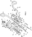
- Figure 1 illustrates the surgical apparatus of the present invention for driving staples one at a time through body tissue and against a staple deforming anvil.
- the apparatus comprises an actuating handle 20, an anvil jaw 30 coupled to the actuating handle 20, and a stationary elongated handle 10 terminating at its distal end in a staple carrying jaw 40.
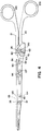
- Anvil jaw 30 is positioned opposite staple carrying jaw 40 and is pivotable around pin 107 by handle 20 from an open position spaced from staple carrying jaw 40 ( Figure 1) to a closed position adjacent staple carrying jaw 40 to clamp tissue therebetween ( Figure 3).
- a staple cartridge 50 is mounted atop staple carrying jaw 40 and includes a pusher member for driving the individual staples which is also actuated by handle 20. Both handles 10 and 20 terminate at their proximal ends in finger loops 101, 201, respectively, to facilitate manipulation by the user.
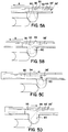
- Anvil jaw 30 includes a pair of depressions 307 (only one of which is shown in Figures 6A, 6B) dimensioned to receive the legs of the staples S to form them into a B-shaped configuration as shown.
- Anvil jaw 30 preferably includes an angled wall 305 to block the entry of tissue from the instrument as well as to provide a guide for the staples. Wall 305 may optionally terminate in a pair of tissue prongs to further prevent tissue from interfering with the staple pusher or staples during formation.
- transverse guide pin 26 forms part of the linkage mechanism for clamping the tissue and driving the staples.
- Pivot pin 35 mounts anvil jaw 30 to staple carrying jaw 40 for pivotal movement thereof upon actuation of handle 20.
- the linkage mechanism comprises a pair of elongated links 62, a mounting plate 70, and a saddle 80, all of which are mounted through aperture 201 of handle 20 and linkage track 120 of elongated handle 10 via guide pin 26. More specifically, guide pin 26 extends through mounting openings 72 in mounting plate 70 and slides in angled cam slots 63 of elongated links 62 and in angled tracks 82 of saddle 80. Pivot pin 35 extends through slots 67 in elongated links 62, holes 303 in anvil jaw 30, and aperture 128 in elongated handle 10.
- a camming pin 69 is mounted through rear opening 301 in anvil jaw 30, diagonal slots 65 in elongated links 62 and small slot 126 in elongated handle 10.
- guide pin 26 travels upwardly in the vertical portion of angled track 82 and diagonally in the slanted portion of angled cam slot 63.
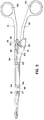
- saddle 80 remains stationary while mounting plate 70 pivots to drive elongated links 62 distally causing anvil jaw 30 to pivot around pivot pin 35 as camming pin 69 slides diagonally rearwardly in diagonal slots 65. This clamping position of the jaws is shown in Figure 3.
- FIG. 2 Further mounting of the components of the linkage mechanism is apparent from Figure 2 wherein mounting slots 64 of elongated links 62 are in alignment with hole 122 of elongated handle 10, elongated slots 66 are in alignment with hole 124, and central channels 68 are in alignment with central elongated channel 127.
- Saddle 80 straddles elongated links 62, so that central longitudinal channels 84 cooperate with mounting slots 64 and distal longitudinal channels 86 cooperate with elongated slots 66.
- Mounting plate 70 straddles saddle 80 such that its distal apertures 74 are aligned with distal longitudinal channels 86. Note that only one of the links 62 is labelled in Figure 2 for purposes of clarity.
- a handle return mechanism is provided which includes a bracket 94 and a coil spring 96.
- Bracket 94 is mounted within channel 127 of elongated handle 10 and central channels 68 of elongated links 62, and biases elongated links 62 in a proximal rest position.
- a pair of curved staple surfaces 44 to support and guide the staple into contact with the anvil depressions are provided.
- Retaining plate 42 is secured atop curved staple surfaces 44 and retains and bends the staple pusher around these surfaces in the manner described below.
- the staple cartridge designated generally by reference numeral 50, and with reference to Figures 2, 6A and 7A, includes a fixed lower rack 54 mounted within a retaining channel 56, an upper rack 55 mounted over retaining channel 56, and a cartridge cover 59.
- a plurality of staples are aligned longitudinally in channel 56, with the legs pointing distally so that the legs of each staple contacts the crown portion of the next staple.
- Rails 58 of retaining channel 56 prevent transverse movement of the staples with respect to the longitudinal axis.
- Pusher finger 51 is welded to an upper surface portion of cartridge cover 59 and is configured to contact the crown of the distalmost staple to advance it towards anvil jaw 30.
- Pusher finger 51 slides underneath retaining plate 42 of jaw 40, and is flexed by the retaining plate 42 around curved surfaces 44.
- a stack pusher 52 is mounted between lower and upper racks 54, 55 and positioned behind the proximalmost staple of the stack of staples to push the entire stack distally so that the distalmost staple is positioned proximal to curved surfaces 44 of staple jaw 40 for engagement and subsequent advancement by pusher finger 51.
- Lower rack 54 fixedly mounted atop handle 10 through aligned rear opening 540 and hole 123, includes a set of bottom teeth 53 (see also Figure 8A) longitudinally aligned along each of its sides to receive a pair of bottom wings 522 of stack pusher 52. Top wings 524 of stack pusher 52 engage the upper teeth 57 ( Figure 8B) which are also formed on both sides of upper rack 55. Bottom teeth 53 and upper teeth 57 are configured and angled as shown to advantageously allow stack pusher 52 to move distally in the direction of arrow A when upper rack 55 is advanced while preventing proximal movement in the direction of arrow B when upper rack 55 is retracted as described below.
- Cartridge cover 59 in conjunction with sliding movement of saddle 80 provides a mechanism for driving pusher finger 51 to advance each individual staple into the tissue as well as a mechanism for driving stack pusher 52 to advance the entire stack of staples.
- Cartridge cover 59 is mounted to saddle 80 by fastener 89 extending through aligned top opening 88 and rear hole 592.
- Cartridge pin 595 extends through hole 590 in cover 59 into slidable engagement with slot 550 in upper rack 55.
- cartridge pin 595 When cartridge pin 595 reaches the distal edge of slot 550 as shown in phantom in Figure 7B, upper rack 55 is engaged and is carried forwardly by pin 595. This advances stack pusher 52 in the direction of arrow A of Figures 8A and 8B a sufficient distance to advance the distalmost staple into position for engagement by distal finger 52 on the next firing stroke. Incremental movement of stack pusher 52 is ensured by teeth 57, 53.
- a ratchet mechanism comprising a ratchet 90 and ratchet plate 92 is provided as a safety mechanism to require completion of a staple firing stroke once initiated.
- Ratchet plate 92 is attached to the inner surface of the upper wall 81 of saddle 80 by welding or any other suitable means.
- Ratchet 90 sits within a recess in elongated handle 10, with its tooth portion extending upwardly into contact with ratchet plate 92, as best shown in Figures 1 and in the enlarged view of Figure 5A.
- Ratchet plate 92 includes recessed portions 95, 95' at each end, central planar surface 94, and camming surfaces 93, 93'.
- ratchet plate 92 When ratchet plate 92 is carried forwardly by saddle 80 in the direction of arrow A of Figures 5A and 5B, the tooth portion of ratchet 90 rides along camming surface 93 and is biased distally by planar surface 92. In this forwardly biased position, ratchet 90 effectively prevents ratchet plate 92 from sliding rearwardly until rear recess 95' is positioned thereabove and the tooth portion is allowed to pivot back to its vertical position as shown in Figure 5C. At this point the staple firing stroke is completed. The return of ratchet plate 92 to its retracted position biases ratchet 90 rearwardly (Figure 5D) as it rides over camming surface 93' and into engagement with planar surface 94. Ratchet 90 returns to its vertical position when ratchet plate 92 is retracted sufficiently rearwardly such that recessed portion 95 overlies the tooth portion as shown in Figure 5A.
- handles 10 and 20 are spaced apart so that anvil jaw 30 is spaced from staple jaw 40.
- guide pin 26 is seated in the lowermost position of angled cam slots 63 of elongated links 62 and in the lowermost position of angled track 82 of saddle 80. It is also positioned at the bottom of linkage track 120 of elongated handle 10.
- mounting plate connecting pin 107 which extends through distal aperture 74 of mounting plate 70, is located in the distalmost position of longitudinal slots 66 of elongated links 62 and is seated through hole 124 of elongated handle 10.
- Proximal connecting pin 103 is positioned in the distalmost portion of aligned mounting slots 64 of elongated links 62 and in hole 122 of elongated handle 10. In this open position, cam pin 69 is located in the uppermost region at the intersection of diagonal slot 65 of elongated link 62 and small slot 126 of elongated handle 10.
- This dwell position corresponds to the point when guide pin 26 has completed its diagonally directed travel in angled cam slot 63 but has not yet started its oblique travel in angled track 82, i.e. is in the overlapping vertical portions of slot 63 and track 82.
- this dwell position advantageously signals the user that the staple advancing mechanism will be actuated if the handles are continued to be squeezed, but provides sufficient time to unclamp the tissue prior to such actuation.
- actuating handle 10 is continuously squeezed, causing guide pin 26 to travel diagonally upwardly in angled track 82 of saddle 80.
- This third movement of actuating handle 20 translates to distal movement of saddle 80 with longitudinal channels 84 and 86 travelling along fixed center connecting pin 107 and proximal connecting pin 103 as shown in Figure 4.
- camming surface 93 of ratchet 90 engages central planar surface 94 of ratchet plate 92, as shown in Figure 5B to prevent proximal movement of saddle 80 until completion of the firing stroke.
- Upper rack 55 moves stack pusher 52 distally a distance equal to the length of a staple, as its upper wings 524 and lower wings 522 step over upper teeth 57 and lower teeth 52, respectively.
- the stack of staples is advanced so the distalmost staple is moved to the ready position proximal to curved surfaces 44 for engagement by pusher finger 51 in the next firing stroke.
- the positioning of the components upon firing of the apparatus is shown in Figure 4, with guide pin 26 in the uppermost region of angled track 82 and pins 107, 103 in the proximalmost portion of channels 84, 86.
- handle 20 In the return stroke after firing of the staple, handle 20 is released and guide pin 26 travels diagonally forwardly in angled track 82 of saddle 80 to retract saddle 80 proximally. Proximal movement of saddle 80 retracts cover 59 and subsequently upper rack 55 as pin 595 engages the proximal edge of slot 550. The engagement of lower wings 522 with lower teeth 53 of lower rack 54 prevents stack pusher 52 from being retracted along with upper rack 55. Pusher finger 51 steps over the distalmost staple and returns to its retracted position in contact with the crown portion of the distalmost staple.
- the instrument of the present invention has particular application to vascular tissue, although it can be used to attach or close openings in other types of body tissue.
- the clamping and closing of individual vessels to effect hemostasis by the stapling apparatus of the present invention saves the surgeon valuable time.
- the stapling apparatus of the present invention can also be used to attach approximated vessels or vessel portions by inserting each leg of the staple through one of the approximated vessels or vessel portions.
- the B-shaped formation of the legs provides advantageous attachment of the approximated vessels.
- the instrument of the present invention can also be used in laparoscopic or endoscopic procedures. That is, the instrument with its handles and jaws closed, can be inserted through a small incision in the body or through a narrow endoscopic tube which is positioned through a small opening in the skin and extends into the interior of the body. After insertion, the jaws can be opened and then closed around the body tissue, and a staple can be applied by further manipulation of the handles.
Applications Claiming Priority (2)
| Application Number | Priority Date | Filing Date | Title |
|---|---|---|---|
| US78169691A | 1991-10-18 | 1991-10-18 | |
| US781696 | 1991-10-18 |
Publications (2)
| Publication Number | Publication Date |
|---|---|
| EP0537757A2 true EP0537757A2 (fr) | 1993-04-21 |
| EP0537757A3 EP0537757A3 (en) | 1993-06-30 |
Family
ID=25123609
Family Applications (1)
| Application Number | Title | Priority Date | Filing Date |
|---|---|---|---|
| EP19920117706 Withdrawn EP0537757A3 (en) | 1991-10-18 | 1992-10-16 | Surgical stapling apparatus |
Country Status (3)
| Country | Link |
|---|---|
| US (1) | US5337937A (fr) |
| EP (1) | EP0537757A3 (fr) |
| CA (1) | CA2079058A1 (fr) |
Cited By (2)
| Publication number | Priority date | Publication date | Assignee | Title |
|---|---|---|---|---|
| EP0591946A1 (fr) * | 1992-10-06 | 1994-04-13 | United States Surgical Corporation | Appareil d'attache chirurgical |
| US5486187A (en) * | 1994-01-04 | 1996-01-23 | Schenck; Robert R. | Anastomosis device and method |
Families Citing this family (71)
| Publication number | Priority date | Publication date | Assignee | Title |
|---|---|---|---|---|
| US5601224A (en) | 1992-10-09 | 1997-02-11 | Ethicon, Inc. | Surgical instrument |
| US5501689A (en) * | 1994-02-03 | 1996-03-26 | United States Surgical Corporation | Plaque stapler |
| US5470007A (en) * | 1994-05-02 | 1995-11-28 | Minnesota Mining And Manufacturing Company | Laparoscopic stapler with overload sensor and interlock |
| US5820009A (en) * | 1996-02-20 | 1998-10-13 | Richard-Allan Medical Industries, Inc. | Articulated surgical instrument with improved jaw closure mechanism |
| US5954746A (en) * | 1997-10-09 | 1999-09-21 | Ethicon Endo-Surgery, Inc. | Dual cam trigger for a surgical instrument |
| US7239902B2 (en) * | 2001-03-16 | 2007-07-03 | Nellor Puritan Bennett Incorporated | Device and method for monitoring body fluid and electrolyte disorders |
| US6591122B2 (en) * | 2001-03-16 | 2003-07-08 | Nellcor Puritan Bennett Incorporated | Device and method for monitoring body fluid and electrolyte disorders |
| US7657292B2 (en) * | 2001-03-16 | 2010-02-02 | Nellcor Puritan Bennett Llc | Method for evaluating extracellular water concentration in tissue |
| US8135448B2 (en) * | 2001-03-16 | 2012-03-13 | Nellcor Puritan Bennett Llc | Systems and methods to assess one or more body fluid metrics |
| US7950559B2 (en) | 2002-06-25 | 2011-05-31 | Incisive Surgical, Inc. | Mechanical method and apparatus for bilateral tissue fastening |
| US20120145765A1 (en) | 2002-06-25 | 2012-06-14 | Peterson James A | Mechanical method and apparatus for bilateral tissue fastening |
| US6726705B2 (en) | 2002-06-25 | 2004-04-27 | Incisive Surgical, Inc. | Mechanical method and apparatus for bilateral tissue fastening |
| US8074857B2 (en) | 2002-06-25 | 2011-12-13 | Incisive Surgical, Inc. | Method and apparatus for tissue fastening with single translating trigger operation |
| US7112214B2 (en) | 2002-06-25 | 2006-09-26 | Incisive Surgical, Inc. | Dynamic bioabsorbable fastener for use in wound closure |
| CA2409471C (fr) * | 2002-10-23 | 2010-10-12 | Lsi - Lift Systems Incorporated | Sac en vrac et element rigide combines pour la reception de fourches de leve-palettes |
| US8714429B2 (en) * | 2003-04-29 | 2014-05-06 | Covidien Lp | Dissecting tip for surgical stapler |
| US9597078B2 (en) * | 2003-04-29 | 2017-03-21 | Covidien Lp | Surgical stapling device with dissecting tip |
| US7277741B2 (en) * | 2004-03-09 | 2007-10-02 | Nellcor Puritan Bennett Incorporated | Pulse oximetry motion artifact rejection using near infrared absorption by water |
| WO2007013906A2 (fr) | 2005-07-15 | 2007-02-01 | Incisive Surgical, Inc. | Systeme de surveillance de la pression intra-abdominale |
| US8255025B2 (en) * | 2006-06-09 | 2012-08-28 | Nellcor Puritan Bennett Llc | Bronchial or tracheal tissular water content sensor and system |
| US8180419B2 (en) * | 2006-09-27 | 2012-05-15 | Nellcor Puritan Bennett Llc | Tissue hydration estimation by spectral absorption bandwidth measurement |
| US7643858B2 (en) * | 2006-09-28 | 2010-01-05 | Nellcor Puritan Bennett Llc | System and method for detection of brain edema using spectrophotometry |
| US8116852B2 (en) * | 2006-09-29 | 2012-02-14 | Nellcor Puritan Bennett Llc | System and method for detection of skin wounds and compartment syndromes |
| US8280469B2 (en) | 2007-03-09 | 2012-10-02 | Nellcor Puritan Bennett Llc | Method for detection of aberrant tissue spectra |
| US8175665B2 (en) | 2007-03-09 | 2012-05-08 | Nellcor Puritan Bennett Llc | Method and apparatus for spectroscopic tissue analyte measurement |
| US8690864B2 (en) * | 2007-03-09 | 2014-04-08 | Covidien Lp | System and method for controlling tissue treatment |
| US8346327B2 (en) | 2007-03-09 | 2013-01-01 | Covidien Lp | Method for identification of sensor site by local skin spectrum data |
| US20080221411A1 (en) * | 2007-03-09 | 2008-09-11 | Nellcor Puritan Bennett Llc | System and method for tissue hydration estimation |
| US8109882B2 (en) | 2007-03-09 | 2012-02-07 | Nellcor Puritan Bennett Llc | System and method for venous pulsation detection using near infrared wavelengths |
| US8357090B2 (en) * | 2007-03-09 | 2013-01-22 | Covidien Lp | Method and apparatus for estimating water reserves |
| BRPI0817421A2 (pt) | 2007-10-05 | 2015-06-16 | Tyco Healthcare | Fixador de vedação para uso em procedimentos cirúrgicos |
| US20100100043A1 (en) * | 2007-10-05 | 2010-04-22 | Racenet Danyel J | Flexible Access Device For Use In Surgical Procedure |
| US8406865B2 (en) * | 2008-09-30 | 2013-03-26 | Covidien Lp | Bioimpedance system and sensor and technique for using the same |
| USD738500S1 (en) | 2008-10-02 | 2015-09-08 | Covidien Lp | Seal anchor for use in surgical procedures |
| US9023069B2 (en) | 2009-05-18 | 2015-05-05 | Covidien Lp | Attachable clamp for use with surgical instruments |
| KR101156086B1 (ko) | 2009-10-28 | 2012-06-20 | 국립암센터 | 수술기구 |
| US9844377B2 (en) | 2014-04-25 | 2017-12-19 | Incisive Surgical, Inc. | Method and apparatus for wound closure with sequential tissue positioning and retention |
| US10064649B2 (en) | 2014-07-07 | 2018-09-04 | Covidien Lp | Pleated seal for surgical hand or instrument access |
| US9707011B2 (en) | 2014-11-12 | 2017-07-18 | Covidien Lp | Attachments for use with a surgical access device |
| CA3195821A1 (fr) * | 2014-12-23 | 2016-06-30 | Applied Medical Resources Corporation | Dispositif de fermeture hermetique et de division electrochirurgical bipolaire |
| USD752219S1 (en) | 2015-01-02 | 2016-03-22 | Incisive Surgical, Inc. | Tissue fastening instrument |
| US10085747B2 (en) | 2015-09-11 | 2018-10-02 | Incisive Surgical, Inc. | Surgical fastening instrument |
| US11160682B2 (en) | 2017-06-19 | 2021-11-02 | Covidien Lp | Method and apparatus for accessing matter disposed within an internal body vessel |
| US10828065B2 (en) | 2017-08-28 | 2020-11-10 | Covidien Lp | Surgical access system |
| US10675056B2 (en) | 2017-09-07 | 2020-06-09 | Covidien Lp | Access apparatus with integrated fluid connector and control valve |
| US10786252B2 (en) * | 2018-07-16 | 2020-09-29 | Ethicon Llc | Surgical stapling end effector component with deformable tip having void |
| US11278285B2 (en) * | 2018-08-13 | 2022-03-22 | Cilag GbmH International | Clamping assembly for linear surgical stapler |
| US11389193B2 (en) | 2018-10-02 | 2022-07-19 | Covidien Lp | Surgical access device with fascial closure system |
| US11457949B2 (en) | 2018-10-12 | 2022-10-04 | Covidien Lp | Surgical access device and seal guard for use therewith |
| US10792071B2 (en) | 2019-02-11 | 2020-10-06 | Covidien Lp | Seals for surgical access assemblies |
| US11166748B2 (en) | 2019-02-11 | 2021-11-09 | Covidien Lp | Seal assemblies for surgical access assemblies |
| US11000313B2 (en) | 2019-04-25 | 2021-05-11 | Covidien Lp | Seals for surgical access devices |
| US11413068B2 (en) | 2019-05-09 | 2022-08-16 | Covidien Lp | Seal assemblies for surgical access assemblies |
| US11259841B2 (en) | 2019-06-21 | 2022-03-01 | Covidien Lp | Seal assemblies for surgical access assemblies |
| US11357542B2 (en) | 2019-06-21 | 2022-06-14 | Covidien Lp | Valve assembly and retainer for surgical access assembly |
| US11259840B2 (en) | 2019-06-21 | 2022-03-01 | Covidien Lp | Valve assemblies for surgical access assemblies |
| US11413065B2 (en) | 2019-06-28 | 2022-08-16 | Covidien Lp | Seal assemblies for surgical access assemblies |
| US11399865B2 (en) | 2019-08-02 | 2022-08-02 | Covidien Lp | Seal assemblies for surgical access assemblies |
| US11523842B2 (en) | 2019-09-09 | 2022-12-13 | Covidien Lp | Reusable surgical port with disposable seal assembly |
| US11432843B2 (en) | 2019-09-09 | 2022-09-06 | Covidien Lp | Centering mechanisms for a surgical access assembly |
| US11812991B2 (en) | 2019-10-18 | 2023-11-14 | Covidien Lp | Seal assemblies for surgical access assemblies |
| US11464540B2 (en) | 2020-01-17 | 2022-10-11 | Covidien Lp | Surgical access device with fixation mechanism |
| US11576701B2 (en) | 2020-03-05 | 2023-02-14 | Covidien Lp | Surgical access assembly having a pump |
| US11642153B2 (en) | 2020-03-19 | 2023-05-09 | Covidien Lp | Instrument seal for surgical access assembly |
| US11541218B2 (en) | 2020-03-20 | 2023-01-03 | Covidien Lp | Seal assembly for a surgical access assembly and method of manufacturing the same |
| US11446058B2 (en) | 2020-03-27 | 2022-09-20 | Covidien Lp | Fixture device for folding a seal member |
| US11717321B2 (en) | 2020-04-24 | 2023-08-08 | Covidien Lp | Access assembly with retention mechanism |
| US11622790B2 (en) | 2020-05-21 | 2023-04-11 | Covidien Lp | Obturators for surgical access assemblies and methods of assembly thereof |
| WO2021252817A1 (fr) * | 2020-06-10 | 2021-12-16 | The Regents Of The University Of California | Agrafeuse endoscopique et extracteur d'agrafes |
| US11751908B2 (en) | 2020-06-19 | 2023-09-12 | Covidien Lp | Seal assembly for surgical access assemblies |
| CN113081117A (zh) * | 2021-04-20 | 2021-07-09 | 南京鼓楼医院 | 鼻中隔术后吻合器 |
Citations (4)
| Publication number | Priority date | Publication date | Assignee | Title |
|---|---|---|---|---|
| US2874384A (en) * | 1957-04-16 | 1959-02-24 | Rockford Medical Foundation | Surgical device |
| CH376223A (fr) * | 1960-02-04 | 1964-03-31 | F Gudow Wassili | Instrument chirurgical pour suturer les vaisseaux sanguins, les intestins, les bronches et autres tissus mous |
| US3604561A (en) * | 1969-08-07 | 1971-09-14 | Codman & Shurtleff | Multiple stapler cartridge |
| EP0167217A1 (fr) * | 1984-05-10 | 1986-01-08 | Ethicon, Inc. | Instrument d'agrafage chirurgical |
Family Cites Families (22)
| Publication number | Priority date | Publication date | Assignee | Title |
|---|---|---|---|---|
| US1452373A (en) * | 1921-10-15 | 1923-04-17 | Gomez Joaquin Sanchez | Surgical ligature and means for applying the same |
| GB319886A (en) * | 1928-08-20 | 1929-10-03 | Arthur Cloudesley Smith | Improved means applicable for use in surgery in sealing arteries, clipping tissues and the like |
| US2301622A (en) * | 1942-03-03 | 1942-11-10 | Frederic E Hambrecht | Hemostat |
| US2853074A (en) * | 1956-06-15 | 1958-09-23 | Edward A Olson | Stapling instrument for surgical purposes |
| US3278107A (en) * | 1963-07-24 | 1966-10-11 | Cv Heljestrand Ab | Instrument for applying so-called staple sutures |
| US3269631A (en) * | 1964-06-19 | 1966-08-30 | Takaro Timothy | Surgical stapler |
| CH488448A (de) * | 1968-10-23 | 1970-04-15 | Vnii Khirurgicheskoi Apparatur | Chirurgischer Apparat zum Vernähen von weichen Geweben mittels Klammern |
| US3638847A (en) * | 1970-07-06 | 1972-02-01 | United States Surgical Corp | Ratchet-driven cartridge for surgical instruments |
| US3650453A (en) * | 1970-08-13 | 1972-03-21 | United States Surgical Corp | Staple cartridge with drive belt |
| SU1228830A1 (ru) * | 1976-05-19 | 1986-05-07 | Ивано-Франковский Государственный Медицинский Институт | Сшиватель м гких тканей |
| US4127227A (en) * | 1976-10-08 | 1978-11-28 | United States Surgical Corporation | Wide fascia staple cartridge |
| US4185762A (en) * | 1978-03-27 | 1980-01-29 | Minnesota Mining And Manufacturing Company | Medical stapling device |
| US4204623A (en) * | 1978-07-17 | 1980-05-27 | United States Surgical Corporation | Manually powered surgical stapling instrument |
| SU1237180A1 (ru) * | 1980-02-04 | 1986-06-15 | Ивано-Франковский Государственный Медицинский Институт | Сшиватель м гких тканей |
| US4591086A (en) * | 1980-09-26 | 1986-05-27 | American Cyanamid Company | Surgical stapling instrument |
| US4809695A (en) * | 1981-10-21 | 1989-03-07 | Owen M. Gwathmey | Suturing assembly and method |
| US4471780A (en) * | 1982-02-05 | 1984-09-18 | Ethicon, Inc. | Multiple ligating clip applier instrument |
| SU1090375A1 (ru) * | 1983-01-06 | 1984-05-07 | Всесоюзный научно-исследовательский и испытательный институт медицинской техники | Аппарат дл наложени скобок на ткани |
| US4944443A (en) * | 1988-04-22 | 1990-07-31 | Innovative Surgical Devices, Inc. | Surgical suturing instrument and method |
| JPH0661707B2 (ja) * | 1986-03-18 | 1994-08-17 | 代師行 海老原 | ステ−プラ用カセツト |
| US4821939A (en) * | 1987-09-02 | 1989-04-18 | United States Surgical Corporation | Staple cartridge and an anvilless surgical stapler |
| US4991763A (en) * | 1988-05-23 | 1991-02-12 | Technalytics Inc. | Surgical stapler |
-
1992
- 1992-09-24 CA CA002079058A patent/CA2079058A1/fr not_active Abandoned
- 1992-10-16 EP EP19920117706 patent/EP0537757A3/en not_active Withdrawn
-
1993
- 1993-04-22 US US08/052,223 patent/US5337937A/en not_active Expired - Lifetime
Patent Citations (4)
| Publication number | Priority date | Publication date | Assignee | Title |
|---|---|---|---|---|
| US2874384A (en) * | 1957-04-16 | 1959-02-24 | Rockford Medical Foundation | Surgical device |
| CH376223A (fr) * | 1960-02-04 | 1964-03-31 | F Gudow Wassili | Instrument chirurgical pour suturer les vaisseaux sanguins, les intestins, les bronches et autres tissus mous |
| US3604561A (en) * | 1969-08-07 | 1971-09-14 | Codman & Shurtleff | Multiple stapler cartridge |
| EP0167217A1 (fr) * | 1984-05-10 | 1986-01-08 | Ethicon, Inc. | Instrument d'agrafage chirurgical |
Cited By (3)
| Publication number | Priority date | Publication date | Assignee | Title |
|---|---|---|---|---|
| US5366134A (en) * | 1991-10-18 | 1994-11-22 | United States Surgical Corporation | Surgical fastening apparatus |
| EP0591946A1 (fr) * | 1992-10-06 | 1994-04-13 | United States Surgical Corporation | Appareil d'attache chirurgical |
| US5486187A (en) * | 1994-01-04 | 1996-01-23 | Schenck; Robert R. | Anastomosis device and method |
Also Published As
| Publication number | Publication date |
|---|---|
| US5337937A (en) | 1994-08-16 |
| CA2079058A1 (fr) | 1993-04-19 |
| EP0537757A3 (en) | 1993-06-30 |
Similar Documents
| Publication | Publication Date | Title |
|---|---|---|
| US5337937A (en) | Surgical stapling apparatus | |
| US5366134A (en) | Surgical fastening apparatus | |
| US6446854B1 (en) | Surgical stapling apparatus | |
| US9968361B2 (en) | Clip applying apparatus with angled jaw | |
| US5618311A (en) | Surgical subcuticular fastener system | |
| US5779718A (en) | Method of anastomosing a vessel using a surgical clip applier | |
| US4819853A (en) | Surgical fastener cartridge | |
| US20170181741A1 (en) | Endoscopic purse string surgical device | |
| US5868761A (en) | Surgical clip applier | |
| US5431668A (en) | Ligating clip applier | |
| US4616650A (en) | Apparatus for applying surgical clips | |
| CN1732859B (zh) | 具有两件式e形梁发射机构的铰接手术缝合器 | |
| US3844289A (en) | Hemostat and attachment for suturing organic tubular structures | |
| US5409498A (en) | Rotatable articulating endoscopic fastening instrument | |
| US5364003A (en) | Staple cartridge for a surgical stapler | |
| US5690269A (en) | Endoscopic stapler | |
| EP0594004B1 (fr) | Instrument pour poser des agrafes chirurgicales | |
| US6652545B2 (en) | Ligation clip and clip applier | |
| EP1813214A1 (fr) | Attache chirurgicale et instrument de pose | |
| JPH06125913A (ja) | ナイフ手段を備えた腹腔鏡ステープラー | |
| JPH09531A (ja) | 無菌閉鎖ファスナならびにその装着装置 | |
| JPH07236644A (ja) | 外科手術用クリップアプライヤ | |
| JP2003235854A (ja) | 無菌クリップと配置器械 | |
| JPH0257935B2 (fr) | ||
| CA2640781A1 (fr) | Enclume en deux morceaux pour agrafeuse chirurgicale |
Legal Events
| Date | Code | Title | Description |
|---|---|---|---|
| PUAI | Public reference made under article 153(3) epc to a published international application that has entered the european phase |
Free format text: ORIGINAL CODE: 0009012 |
|
| AK | Designated contracting states |
Kind code of ref document: A2 Designated state(s): DE FR GB IT |
|
| PUAL | Search report despatched |
Free format text: ORIGINAL CODE: 0009013 |
|
| AK | Designated contracting states |
Kind code of ref document: A3 Designated state(s): DE FR GB IT |
|
| 17P | Request for examination filed |
Effective date: 19931201 |
|
| STAA | Information on the status of an ep patent application or granted ep patent |
Free format text: STATUS: THE APPLICATION HAS BEEN WITHDRAWN |
|
| 18W | Application withdrawn |
Withdrawal date: 19940921 |