EP0536703A1 - Dispositif pour transformer un flux à plusieurs voies de récipients en une seule file de récipients - Google Patents
Dispositif pour transformer un flux à plusieurs voies de récipients en une seule file de récipients Download PDFInfo
- Publication number
- EP0536703A1 EP0536703A1 EP92117053A EP92117053A EP0536703A1 EP 0536703 A1 EP0536703 A1 EP 0536703A1 EP 92117053 A EP92117053 A EP 92117053A EP 92117053 A EP92117053 A EP 92117053A EP 0536703 A1 EP0536703 A1 EP 0536703A1
- Authority
- EP
- European Patent Office
- Prior art keywords
- conveyor
- transport direction
- belts
- arrangement according
- transport
- Prior art date
- Legal status (The legal status is an assumption and is not a legal conclusion. Google has not performed a legal analysis and makes no representation as to the accuracy of the status listed.)
- Withdrawn
Links
Images


Classifications
-
- B—PERFORMING OPERATIONS; TRANSPORTING
- B65—CONVEYING; PACKING; STORING; HANDLING THIN OR FILAMENTARY MATERIAL
- B65G—TRANSPORT OR STORAGE DEVICES, e.g. CONVEYORS FOR LOADING OR TIPPING, SHOP CONVEYOR SYSTEMS OR PNEUMATIC TUBE CONVEYORS
- B65G47/00—Article or material-handling devices associated with conveyors; Methods employing such devices
- B65G47/52—Devices for transferring articles or materials between conveyors i.e. discharging or feeding devices
- B65G47/68—Devices for transferring articles or materials between conveyors i.e. discharging or feeding devices adapted to receive articles arriving in one layer from one conveyor lane and to transfer them in individual layers to more than one conveyor lane or to one broader conveyor lane, or vice versa, e.g. combining the flows of articles conveyed by more than one conveyor
- B65G47/682—Devices for transferring articles or materials between conveyors i.e. discharging or feeding devices adapted to receive articles arriving in one layer from one conveyor lane and to transfer them in individual layers to more than one conveyor lane or to one broader conveyor lane, or vice versa, e.g. combining the flows of articles conveyed by more than one conveyor from a single conveyor lane consisting of one conveyor or several adjacent conveyors
-
- B—PERFORMING OPERATIONS; TRANSPORTING
- B65—CONVEYING; PACKING; STORING; HANDLING THIN OR FILAMENTARY MATERIAL
- B65G—TRANSPORT OR STORAGE DEVICES, e.g. CONVEYORS FOR LOADING OR TIPPING, SHOP CONVEYOR SYSTEMS OR PNEUMATIC TUBE CONVEYORS
- B65G47/00—Article or material-handling devices associated with conveyors; Methods employing such devices
- B65G47/52—Devices for transferring articles or materials between conveyors i.e. discharging or feeding devices
- B65G47/68—Devices for transferring articles or materials between conveyors i.e. discharging or feeding devices adapted to receive articles arriving in one layer from one conveyor lane and to transfer them in individual layers to more than one conveyor lane or to one broader conveyor lane, or vice versa, e.g. combining the flows of articles conveyed by more than one conveyor
- B65G2047/685—Devices for preventing jamming in converging flows
- B65G2047/687—Lane boundaries which comprise rotatable elements, e.g. discs, cylinders, endless belts
Definitions
- the invention relates to an arrangement according to the preamble of claim 1.
- An arrangement of this type is known (EP-A-0 252 461).
- a conveyed multi-lane bottle flow is converted in two stages into the single-lane bottle flow to be discharged on the intermediate conveyor and on the discharge conveyor, in such a way that at the exit region of the intermediate conveyor there is still a two-lane bottle flow, which is then finally on the conveyor in the single-lane Bottle stream is formed.
- the intermediate conveyor forms one of guides in its forming area, i.e. from there guiding railings laterally delimited aisle, the track or conveyor width of which decreases in the transport direction in a funnel-like manner and symmetrically to a horizontal central axis running in the transport direction.
- the intermediate conveyor is designed in its forming area as an acceleration section for the bottles, i.e. there it consists of several conveyor belts, some of which are also narrow conveyor belts and form groups or conveyor sections with conveyor belts adjoining one another in the transport direction.
- the conveyor belts can be driven at different speeds in such a way that the conveying speed increases in the direction of transport.
- the object of the invention is to provide an arrangement which enables low-pressure conveying of the containers or, as an alternative to the prior art, allows low-pressure reshaping of a conveyed multi-lane container flow into a single-lane container flow to be discharged at high output in only one stage.
- the intermediate conveyor forms a lane on the forming area formed exclusively on the intermediate conveyor, which narrows symmetrically to the central axis up to the exit area of the intermediate conveyor or until the conveying or track width corresponding to the single-track container flow, at the same time also the removal conveyor at least this output area lies with its axis coaxially with the central axis.
- the entire forming area of the intermediate conveyor, its connection or transition to the discharge conveyor, as well as the alley of the discharge conveyor directly adjacent to the intermediate conveyor with the track or conveyor width corresponding to the single-track container flow are thus regarding their shape and arrangement as well as grouping of the second conveyor belts or the conveyor sections formed by these and their speed gradations symmetrical to the central axis M. Optimal acceleration or loosening and merging of the containers of the multi-lane container flow into the single-lane container flow are thus achieved at the forming area.
- the arrangement according to the invention is part of a conveyor line, as is usually used in container or bottle treatment lines for connecting the machines provided there (unpacker, washing and cleaning machine, filling machine, sealing machine, labeling machine and / or packer, etc.)
- the entire conveyor line consists exclusively of narrow conveyor belts.
- “Narrow conveyor belts” in the sense of the invention are conveyor belts, the width of which is smaller than the diameter of the containers or bottles to be processed at the bottom, in such a way that each container stands on at least two conveyor belts which are adjacent to one another transversely to the transport direction .
- the containers have, for example, a bottom diameter greater than 40 mm.
- the width of the "narrow" conveyor belts is, for example, 32 mm.
- the comb-like staggered transitions further ensure that the containers pass these transitions essentially without changing their direction.
- successive conveying sections can also be achieved at different speeds in the transport direction, i.e. for example, the conveying speed of the containers can be gradually increased.
- low-pressure conveying by the screw can be achieved in this way.
- Lateral guides of the intermediate conveyor are formed in the arrangement according to the invention, for example, either by guide railings or by at least one inner length of an endless element which is driven all the way around such that this length is in Transport direction moved.
- the guides are preferably adjustable perpendicular to the central axis in a horizontal axis direction.
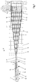
- the arrangement shown in FIG. 1 for reshaping the supplied multi-lane bottle flow consisting of a plurality of bottles 1, ie eight-lane bottle flow in the illustrated embodiment into the single-lane bottle flow to be discharged, consists essentially of a feed conveyor 2, an intermediate conveyor 3 and a discharge conveyor 4.
- Conveyor belts 5 and two guide rails 6 delimiting the track or conveying width of the feed conveyor 2.
- In the embodiment shown are perpendicular to the direction of transport A of the feed conveyor 2, which is also the transport direction of the intermediate conveyor 3 and the discharge conveyor 4, a total of eight conveyor belts 5 are provided laterally one after the other.
- the intermediate conveyor 3 which forms the forming area for converting the multi-lane bottle flow into the single-lane bottle flow, essentially consists of a plurality of conveyor belts 7 driven endlessly and continuously by drives (not shown), some of which adjoin one another in the direction of transportation A, and partially also perpendicular to the direction of transportation A side by side are provided, as well as from two lateral guide rails 8, each of which adjoins a guide rail 6 in the transport direction A and which are arranged in a partial area 3 'forming the entrance area of the intermediate conveyor 3 initially parallel to one another and also parallel to a horizontal central axis M running in the transport direction A. are.
- the guide rails 8 then extend in a partial region 3 ′′ further symmetrically to the central axis M, but obliquely to the central axis M or to the transport direction A, in such a way that the width of the alley formed between the two guide rails 8 for the bottles 1 is constant decreases. In this way, a wedge-shaped, slim forming area is obtained in which the track or conveying width of the intermediate conveyor 3 at its exit area facing away from the feed conveyor 2 finally corresponds to the single-track bottle flow.
- the intermediate conveyor 3 With its input area facing the feed conveyor 2, the intermediate conveyor 3 connects to the feed conveyor 2 in the same way via a transition 9 formed by at least one sliding plate.
- a central conveying section F1 which is provided with its longitudinal extent coaxially with the central axis M and is formed by a plurality of conveyor belts 7 which adjoin one another in the direction of the central axis M or in the transport direction A
- lateral conveyor sections F2-F10 which are each provided in pairs and symmetrically to the central axis M and connect perpendicular to the transport direction A to the central conveyor section F1 or to each other.
- a conveying section F2 is provided on both sides of the central conveying section F1, a conveying section F3, etc. is provided on each side of each conveying section F2.
- all of the conveyor sections F1-F9 in the illustrated embodiment consist of a plurality of conveyor belts 7 adjoining one another in the transport direction A Embodiment, the number of conveyor belts 7 forming a conveyor section F1-F9 and adjoining one another in the transport direction A is greatest at the central conveyor section F1 and decreases from this central conveyor section F1 to the conveyor sections F2-F9 lying further out.
- transitions 10 formed by sheets are provided.
- transitions 10 or the deflections of the conveyor belts 7 are offset like a comb on the adjacent conveyor section F1-F10 in the transport direction A, i.e. each transition 10 or each deflection of a conveyor belt 7 of a conveyor section is perpendicular to the transport direction A the upper run of a conveyor belt 7 adjacent conveyor section and is bridged by this adjacent conveyor belt 7.
- the conveyor belts 7 are each driven.
- the corresponding axes are designated 11 in FIG. 1.
- the last conveyor belt 7 of the central conveyor section F1 forming the exit area of the intermediate conveyor 3 is in the embodiment shown also the conveyor belt of the discharge conveyor 4 and is driven at its front end in the transport direction A by a controlled drive.
- the corresponding axis is designated 11 '.
- the intermediate conveyor 3 is operated as a multi-stage acceleration section, i.e. the drives for the individual conveyor belts 7 are designed such that in each conveyor section F1-F9 each conveyor belt 7 adjoining a conveyor belt 7 in the transport direction A has a higher conveyor speed than the conveyor belt 7 preceding in the transport direction A.
- the conveyor belts 5 and also the conveyor belts 7 each form a horizontal standing or transport surface for the bottles 1 with their upper lengths or their upper runs.
- the guide railings 8 in the two sub-areas 3 'and 3''of the intermediate conveyor 3 are each rectilinear and in the sub-area 3''form an angle of about 15 to 20 ° with the central axis M, so that there results in a relatively slim wedge-shaped forming area.
- the intermediate conveyor 3 is completely symmetrical with respect to the central axis M with regard to the arrangement and grouping of the conveyor belts 7 and the conveyor sections formed by them and also with regard to the graduated, different conveyor speeds of the conveyor belts 7. It goes without saying that the conveying speed of the discharge conveyor 4 is greater than the conveying speed of the feed conveyor 3, namely by a factor which corresponds to the number of tracks of the multi-track bottle flow.
- the discharge conveyor 4 which is arranged symmetrically to the central axis M and already forms an alley for the bottles 1 with a track or conveying width corresponding to the single-track bottle flow, at the exit region of the intermediate conveyor 3, is essentially from the already mentioned conveyor belt 7, which with its longitudinal extension is coaxial with the central axis M, and is formed by two guide railings 12, each of which adjoins a guide railing 8 and which are provided parallel to one another and parallel to the central axis and also equally spaced from it.
- the distance between the two guide rails 12 of course corresponds to the track or. Conveying width of the single-track bottle flow.
- a conveyor 13 connects to the side thereof, which is formed by guide rails 14 and a conveyor belt 15 corresponding to the conveyor belts 5 and on which the bottles 1 of the single-track bottle flow are formed laterally by correspondingly forming the guide rails 14 to be pushed over.
- Sensors 16 are provided on the discharge conveyor 4, which cooperate with a control device (not shown).
- the sensors 16 are used to detect gaps in the bottle flow to be discharged and to control the drives for the conveyor belt 7 forming the discharge conveyor 4, for the intermediate conveyor 3 and the feed conveyor 2 as a function of the stowed position on the discharge conveyor 4.
- This as a dosing conveyor or dosing belt trained feed conveyor 2 in the direction of transport A follows a conveyor designed as a buffer or section of a conveyor, is controlled depending on the performance of an upstream machine so that it optimally doses the number of bottles delivered per unit of time to the intermediate conveyor 3, in such a way that even at a high Performance of the arrangement (number of bottles running through per unit time) after a pressureless merging gives the desired single-track bottle flow in which bottles 1 follow one another without gaps.
- a transition formed by a transfer plate is not necessary at the connection of the discharge conveyor 4 to the intermediate conveyor 3 or in the area of the discharge conveyor 4.
- each belt 17 is guided over two pulleys 19, which are each rotatably mounted on the machine frame of the arrangement about a vertical axis in such a way that each belt 17 guided over the pulleys 19 has a horizontally extending and closer to the central axis M.
- inner length 17 ' forms part of the guide 18 concerned or a guide section for the bottles 1 on the intermediate conveyor 3a.
- each guide 18 with the exception of the pulleys 17 provided at the inlet and outlet of the intermediate conveyor 3a, these are each provided in pairs, axially offset from one another and offset in the vertical direction in such a way that the guide sections formed by the lengths 17 ' Connect each guide 18 overlapping in the direction of transport A.
- the belts 17 are of course driven in such a way that the inner lengths 17 ′ move in the transport direction A, with a stepped drive for the individual belts 17 being provided in the embodiment shown in such a way that each belt 17 following a belt 17 in the transport direction A a guide 18 has a higher speed than the preceding belt 17.
- the speed of the individual belts 17 is further adjusted so that this speed is equal to or approximately equal to the conveying speed of the conveyor belt 7 which the length 17 'of the belt 17 in question is adjacent .
- the guides 18 formed by the circulating belts 17 result in an even further improvement in the unpressurized merging at high outputs, in particular even while avoiding rubbing of the bottles 1 on guide rails.
- the guides 18 and in particular the guide sections formed by the lengths 17 ' are provided running symmetrically to the central axis M, so that on the intermediate conveyor 3a there is a wedge-shaped forming area which is symmetrical to this central axis M and which, in the embodiment according to FIG 2 begins at transition 9.
- lateral guide railings can also be provided in the intermediate conveyor 3a, but these are only effective in the event of malfunctions, for example holding back overturned bottles 1, etc.
- the guides 18 of the intermediate conveyor 3a but also the guide railings 8 of the intermediate conveyor 3 adjustable horizontally and perpendicular to the direction of transport A, as indicated by the double arrow B in FIG. 2.
- the conveyor belts 5 of the feed conveyor 2 can also be narrow conveyor belts, which connect to the feed conveyor 2 again perpendicular to the transport direction A and the width of which is equal to the width of the conveyor belts 7.
- a plurality of transitions corresponding to the transitions 10 are preferably provided, which are then offset like a comb in such a way that the upper run of a conveyor belt 5 or 7 is adjacent to each such transition perpendicular to the transport direction A.
- FIG. 3 shows, as a further possible embodiment, a conveyor line designated 20 in this figure, which, with a section 20 ', forms an arrangement for converting a multi-lane container or bottle stream being conveyed into a single-lane bottle stream to be conveyed away.
- the conveyor section 20, which is only partially shown in FIG. 3, connects in a conventional manner various treatment machines, also not shown in FIG. 3, for example a bottle washer, filling machine (possibly in combination with a capping machine), labeling machine, packer, etc.
- the conveyor section 20 not only in the section 20 ', that is to say in the area of the feed conveyor 2b, the intermediate conveyor 3b and the discharge conveyor 4b of the arrangement there for shaping the bottle flow, only the conveyor belts 7 and corresponding narrow conveyor belts 21 are used, but the entire conveyor section is present also in all other areas or sections 20 ′′ and 20 ′′ ′′ exclusively from the narrow conveyor belts 21, the width of which is equal to the width of the conveyor belts 7 and transverse to the transport direction is smaller than the bottom diameter that the smallest bottles to be processed by the system are 1 (bottles 1 with the smallest bottom diameter). All transitions 9b, 10 and 22 between in the transport direction A adjoining conveyor belts 21, also outside the intermediate conveyor 3b, are each offset in a comb-like manner, as was described above in connection with FIGS. 1 and 2 for the transitions 10.
- the discharge conveyor 4b consists of three conveyor belts 7 arranged side by side in the transport direction A, of which the two outer ends with their front ends in the transport direction A extend into the intermediate conveyor 3b and the middle conveyor belt 7 with its in the transport direction A front end begins approximately at the transition between the intermediate conveyor 3b and the discharge conveyor 4b.
- An advantage of the conveyor line shown in FIG. 3 is, inter alia, in that each bottle 1 always stands on at least two conveyor belts 7 and 21 along the entire conveying path and at least one conveyor belt 7 and 21 at each transition 9b, 10 and 22, so that the bottles 1 are largely depressurized over the transitions 9b, 10 and 22 move, in particular it is not necessary that the bottles 1 to pass the transitions 9b, 10 and 22 are pushed further by subsequent bottles.
- Another advantage is that no bottles remain at the transitions 9b, 10 or 22 if subsequent bottles 1 are missing in the conveying direction. 3 can thus be emptied without manual intervention.
- a further advantage is, inter alia, that the section 20 ′′ of the conveyor section 20 following the discharge conveyor 4b connects to this discharge conveyor in the same direction or in the same direction can, the bottles 1 thus avoid parallel transitions without changing the direction from the conveyor 4b to the section 20 ''.
- the conveyor belts 7 and 21 have a width of approximately 33 mm, for example, so that bottles 1 can be used with the aforementioned advantages, the bottom diameter of which is greater than 40 mm, preferably greater than 45 mm.
- the arrangement is not limited to the conversion of a multi-lane bottle flow into a single-lane bottle flow, but rather the arrangement can generally be used to convert multi-lane container flows, which are formed by bottles, cans or similar containers, into a single-lane container flow.
Landscapes
- Engineering & Computer Science (AREA)
- Mechanical Engineering (AREA)
- Attitude Control For Articles On Conveyors (AREA)
- Control Of Conveyors (AREA)
- Branching, Merging, And Special Transfer Between Conveyors (AREA)
Applications Claiming Priority (4)
| Application Number | Priority Date | Filing Date | Title |
|---|---|---|---|
| DE4133587 | 1991-10-10 | ||
| DE4133587 | 1991-10-10 | ||
| DE4205476 | 1992-02-22 | ||
| DE19924205476 DE4205476A1 (de) | 1991-10-10 | 1992-02-22 | Anordnung zum umformen eines angefoerderten mehrspurigen behaelterstromes in einen abzufoerdernden einspurigen behaelterstrom |
Publications (1)
| Publication Number | Publication Date |
|---|---|
| EP0536703A1 true EP0536703A1 (fr) | 1993-04-14 |
Family
ID=25908108
Family Applications (1)
| Application Number | Title | Priority Date | Filing Date |
|---|---|---|---|
| EP92117053A Withdrawn EP0536703A1 (fr) | 1991-10-10 | 1992-10-06 | Dispositif pour transformer un flux à plusieurs voies de récipients en une seule file de récipients |
Country Status (6)
| Country | Link |
|---|---|
| EP (1) | EP0536703A1 (fr) |
| JP (1) | JPH05310315A (fr) |
| BR (1) | BR9203948A (fr) |
| CA (1) | CA2080205A1 (fr) |
| DE (1) | DE4205476A1 (fr) |
| MX (1) | MX9205811A (fr) |
Cited By (3)
| Publication number | Priority date | Publication date | Assignee | Title |
|---|---|---|---|---|
| EP1293432A1 (fr) * | 2001-09-14 | 2003-03-19 | KHS Maschinen- und Anlagenbau Aktiengesellschaft | Station rotative pour des conteneurs |
| CN111634481A (zh) * | 2020-05-28 | 2020-09-08 | 红云红河烟草(集团)有限责任公司 | 一种烟包翻转装置及系统 |
| WO2023089088A1 (fr) * | 2021-11-22 | 2023-05-25 | Krones Ag | Mise en forme d'un flux massique de récipients pour obtenir un flux de récipients à voie unique |
Citations (5)
| Publication number | Priority date | Publication date | Assignee | Title |
|---|---|---|---|---|
| DE3129389A1 (de) * | 1981-07-25 | 1983-02-10 | Holstein Und Kappert Gmbh, 4600 Dortmund | Verfahren und vorrichtung zum aufteilen und vereinzeln von mehrspurig einlaufenden gefaessen auf eine einreihige spur |
| DE3642764A1 (de) * | 1986-09-19 | 1988-03-31 | Nagema Veb K | Einrichtung zum zusammenfuehren von behaeltern vorzugsweise flaschen |
| DE8711886U1 (fr) * | 1987-09-02 | 1988-09-29 | Krones Ag Hermann Kronseder Maschinenfabrik, 8402 Neutraubling, De | |
| EP0352517A1 (fr) * | 1988-07-08 | 1990-01-31 | Seitz Enzinger Noll Maschinenbau Aktiengesellschaft | Procédé et installation pour transformer un flux de conteneurs arrivant en une seule file en un flux de conteneurs à transporter en plusieurs files |
| EP0441444A1 (fr) * | 1990-02-09 | 1991-08-14 | Speciaal-Machinefabriek J.H. van Uitert B.V. | Dispositif pour grouper des récipients sur une file unique avec une plaque de transfert |
-
1992
- 1992-02-22 DE DE19924205476 patent/DE4205476A1/de not_active Withdrawn
- 1992-10-06 EP EP92117053A patent/EP0536703A1/fr not_active Withdrawn
- 1992-10-08 CA CA 2080205 patent/CA2080205A1/fr not_active Abandoned
- 1992-10-09 JP JP27204292A patent/JPH05310315A/ja not_active Withdrawn
- 1992-10-09 BR BR929203948A patent/BR9203948A/pt not_active Application Discontinuation
- 1992-10-09 MX MX9205811A patent/MX9205811A/es unknown
Patent Citations (5)
| Publication number | Priority date | Publication date | Assignee | Title |
|---|---|---|---|---|
| DE3129389A1 (de) * | 1981-07-25 | 1983-02-10 | Holstein Und Kappert Gmbh, 4600 Dortmund | Verfahren und vorrichtung zum aufteilen und vereinzeln von mehrspurig einlaufenden gefaessen auf eine einreihige spur |
| DE3642764A1 (de) * | 1986-09-19 | 1988-03-31 | Nagema Veb K | Einrichtung zum zusammenfuehren von behaeltern vorzugsweise flaschen |
| DE8711886U1 (fr) * | 1987-09-02 | 1988-09-29 | Krones Ag Hermann Kronseder Maschinenfabrik, 8402 Neutraubling, De | |
| EP0352517A1 (fr) * | 1988-07-08 | 1990-01-31 | Seitz Enzinger Noll Maschinenbau Aktiengesellschaft | Procédé et installation pour transformer un flux de conteneurs arrivant en une seule file en un flux de conteneurs à transporter en plusieurs files |
| EP0441444A1 (fr) * | 1990-02-09 | 1991-08-14 | Speciaal-Machinefabriek J.H. van Uitert B.V. | Dispositif pour grouper des récipients sur une file unique avec une plaque de transfert |
Cited By (4)
| Publication number | Priority date | Publication date | Assignee | Title |
|---|---|---|---|---|
| EP1293432A1 (fr) * | 2001-09-14 | 2003-03-19 | KHS Maschinen- und Anlagenbau Aktiengesellschaft | Station rotative pour des conteneurs |
| CN111634481A (zh) * | 2020-05-28 | 2020-09-08 | 红云红河烟草(集团)有限责任公司 | 一种烟包翻转装置及系统 |
| CN111634481B (zh) * | 2020-05-28 | 2024-04-19 | 红云红河烟草(集团)有限责任公司 | 一种烟包翻转装置及系统 |
| WO2023089088A1 (fr) * | 2021-11-22 | 2023-05-25 | Krones Ag | Mise en forme d'un flux massique de récipients pour obtenir un flux de récipients à voie unique |
Also Published As
| Publication number | Publication date |
|---|---|
| MX9205811A (es) | 1993-05-01 |
| CA2080205A1 (fr) | 1993-04-11 |
| BR9203948A (pt) | 1993-04-27 |
| DE4205476A1 (de) | 1993-04-15 |
| JPH05310315A (ja) | 1993-11-22 |
Similar Documents
| Publication | Publication Date | Title |
|---|---|---|
| EP0399264B1 (fr) | Procédé et dispositif pour changer la position relative de paquets, en particulier de paquets de cigarettes parallélépipédiques du type à couvercle articulé (hinge-lid) | |
| DE2541813C2 (de) | Einrichtung zum Ordnen einer Anzahl ungeordnet herangeführter Behälter zu einer einzigen sich fortbewegenden Reihe | |
| EP0414210B1 (fr) | Procédé et dispositif pour convertir un flux de récipients disposés selon plusieurs pistes en un flux de récipients disposés selon une seule piste | |
| DE3228453C2 (de) | Vorrichtung zum Verbreitern und Verlangsamen eines Stroms aufrechtstehender Flaschen oder dgl. | |
| EP0352517B1 (fr) | Procédé et installation pour transformer un flux de conteneurs arrivant en une seule file en un flux de conteneurs à transporter en plusieurs files | |
| EP2077968B1 (fr) | Parcours de transport | |
| WO1997019853A1 (fr) | Procede et dispositif pour faire tourner des contenants a symetrie de rotation, tels que des bouteilles, pendant leur transport effectue sous pression dynamique | |
| EP0287845A2 (fr) | Dispositif pour transformer un courant de récipients à plusieurs voies en plusieurs files de récipients parallèles séparées entre elles par des éléments de division | |
| EP0512446B1 (fr) | Dispositif pour transformer un courant à plusieures voies de récipients convoyés et très tassés en plusieures files parallèles de récipients, séparés entre eux par des éléments de division | |
| EP2366640B1 (fr) | Unité de transport pour un système de transport pour articles et système de transport correspondant | |
| DE4343477C1 (de) | Verfahren sowie Vorrichtung zum Verteilen von Behältern oder dergleichen Fördergut auf einen mehrreihigen Förderabschnitt | |
| WO2012175161A1 (fr) | Transporteur | |
| EP0536703A1 (fr) | Dispositif pour transformer un flux à plusieurs voies de récipients en une seule file de récipients | |
| EP0252461B1 (fr) | Dispositif de modification d'un flux de bouteilles à plusieurs rangs en un flux de bouteilles à un seul rang | |
| DE3340088A1 (de) | Vorrichtung zum drucklosen umformen eines breiten flaschenstroms zu einem einspurigen flaschenstrom | |
| DE4314644B4 (de) | Vorrichtung zum Ablegen flacher Gegenstände in Hochkantlage auf einem Transportband oder dergleichen | |
| CH689670A5 (de) | Foerderanlage mit einer das seitliche Herabfallen von Stueckguetern verhindernden Seitenfuehrung. | |
| DD252809A1 (de) | Einrichtung zum zusammenfuehren von behaeltern, vorzugsweise mit kreisfoermiger grundflaeche | |
| EP0193878B1 (fr) | Appareil pour transformer un courant large de bouteilles en un courant de sortie à file unique | |
| EP0536702A1 (fr) | Dispositif pour transformer un flux à plusieurs voies de récipients en une seule file de récipients | |
| DD244112A1 (de) | Vorrichtung zum ueberfuehren von gegenstaenden | |
| DE8500522U1 (de) | Vorrichtung zur Zusammenführung eines Flaschenstromes zu einer geschlossenen Flaschenreihe | |
| DE3234286A1 (de) | Vorrichtung zum zusammenfuehren und beschleunigen eines stroms aufrecht stehender flaschen oder dgl. | |
| DE3203177C1 (de) | Schlauchbandförderer für bergbauliche Untertagebetriebe | |
| EP3180279A1 (fr) | Dispositif de transformation d'un flux de récipients étroit en un flux de récipients large |
Legal Events
| Date | Code | Title | Description |
|---|---|---|---|
| PUAI | Public reference made under article 153(3) epc to a published international application that has entered the european phase |
Free format text: ORIGINAL CODE: 0009012 |
|
| AK | Designated contracting states |
Kind code of ref document: A1 Designated state(s): AT BE CH DE DK ES FR GB GR IT LI NL SE |
|
| 17P | Request for examination filed |
Effective date: 19930714 |
|
| RAP1 | Party data changed (applicant data changed or rights of an application transferred) |
Owner name: KHS MASCHINEN- UND ANLAGENBAU AKTIENGESELLSCHAFT |
|
| 17Q | First examination report despatched |
Effective date: 19940727 |
|
| STAA | Information on the status of an ep patent application or granted ep patent |
Free format text: STATUS: THE APPLICATION HAS BEEN WITHDRAWN |
|
| 18W | Application withdrawn |
Withdrawal date: 19941126 |