EP0533700B1 - Dispositif pour l'extraction de spirales d'electrodes introduites dans un organe du corps humain - Google Patents
Dispositif pour l'extraction de spirales d'electrodes introduites dans un organe du corps humain Download PDFInfo
- Publication number
- EP0533700B1 EP0533700B1 EP91910162A EP91910162A EP0533700B1 EP 0533700 B1 EP0533700 B1 EP 0533700B1 EP 91910162 A EP91910162 A EP 91910162A EP 91910162 A EP91910162 A EP 91910162A EP 0533700 B1 EP0533700 B1 EP 0533700B1
- Authority
- EP
- European Patent Office
- Prior art keywords
- pulling element
- head
- handle
- inner wire
- barbs
- Prior art date
- Legal status (The legal status is an assumption and is not a legal conclusion. Google has not performed a legal analysis and makes no representation as to the accuracy of the status listed.)
- Revoked
Links
Images


Classifications
-
- A—HUMAN NECESSITIES
- A61—MEDICAL OR VETERINARY SCIENCE; HYGIENE
- A61N—ELECTROTHERAPY; MAGNETOTHERAPY; RADIATION THERAPY; ULTRASOUND THERAPY
- A61N1/00—Electrotherapy; Circuits therefor
- A61N1/02—Details
- A61N1/04—Electrodes
- A61N1/05—Electrodes for implantation or insertion into the body, e.g. heart electrode
- A61N1/056—Transvascular endocardial electrode systems
- A61N1/057—Anchoring means; Means for fixing the head inside the heart
- A61N2001/0578—Anchoring means; Means for fixing the head inside the heart having means for removal or extraction
Definitions
- the invention relates to a device for extracting a pacemaker electrode spiral that has grown into the heart by exerting a tensile force thereon with a pulling element that can be inserted into the inner lumen of the electrode spiral, with an expandable or expandable pulling element head, the pulling element consisting of a pulling element jacket with a pulling element head attached to it and a longitudinally displaceable inner wire therein consists.
- a frequently used method to remove non-functioning or infected pacemaker electrodes from the body is the so-called permanent tensile stress, in which the electrode is exposed in the pacemaker pocket and is subjected to a permanent tensile stress between 100 and 500 grams for hours and days until the electrode wears out Tissue growth dissolves.
- a weight acts as a tensile load on the electrode by means of a cable guide.
- a disadvantage of this method is that the continuous tensile load must often be applied over several days, with the patient having to linger on the pulling device and in bed.
- the aim of the invention is to make it easier to extract electrode spirals which have already been implanted, have grown in the heart, are not functional or are infected.
- the tensile force required for this should be exerted directly at the place of ingrowth, and an infection of the heart e.g. B. by germs such as z. B. can be caused by advancing the extraction device should be excluded.
- the invention has for its object to provide an easy-to-use extraction instrument that is easy to handle in the introductory phase, the pull-out phase and when the treatment is stopped by an operator and offers the patient the greatest possible safety when extracting .
- an extraction instrument provided with the features known from the cited preamble, which is characterized in that the pulling element head has at least two expandable barbs which are attached to an umbrella head connected to the pulling element and which, after relative displacement between the pulling element and Hook the tension element head into the wall of the inner lumen when the direction of movement of the tension element is reversed.
- this device means considerable relief for the doctor or surgeon and protection for the patient in physical and psychological terms.
- the extraction of ingrown electrodes is also carried out with greater certainty and simplicity according to the teaching according to the invention, because both targeted manipulations by hand are avoided and the outlay on equipment is largely eliminated.
- the traction element consists of a traction element jacket with a traction element head fastened to it and an inner wire which can be displaced longitudinally in the latter enables excellent manipulation of the device, because the inner wire allows certain adjustment and adjustment functions to be carried out.
- tension element head is provided with at least two barbs which can be extended by means of relative displacement of the inner wire and which are arranged on a screen head means that one and the same extraction instrument can be used in a large number of similar but different sized electrode spirals, which increases the safety and the success rate of the intervention .
- a particularly simple introduction of the instrument is given in a particularly advantageous variant, which is designed in such a way that the tension element head contains a chamber for receiving the at least two barbs attached to the umbrella head connected to the tension element and expandable, which after relative displacement between the tension element and The tension element head can be released by pushing it out of the chamber.
- the inner wire in the traction element makes it possible, above all, to activate the variously configurable elements and thus to bring them into connection with the inner wall of the electrode lumen in order to transmit the tractive force to the electrode at the desired locations.
- the extraction of the electrode spiral which has grown too strongly ingrown, can fail in the described manner in individual cases, so that the tension element is to be removed.
- a manually operable device for exerting and transmitting a torque can be connected to the operator-side end of the tension element or the tension element jacket, and, as a modification thereof, the Device be designed in such a way that devices for establishing a rotationally fixed connection between the tension element and the inner wire are arranged in the region of the operator-side ends of the tension element and the inner wire.
- a motor for transmitting a torque can be connected to the operator-side end of the tension element and / or the inner wire.
- the rotational movement between the tension element and the inner wire can also be provided that a rotationally fixed connection can be established between the handle and the retaining ring.
- the handle is provided with a coupling device for the motor provided with a coupling option.
- a handle and a retaining ring are provided, which are connected to the inner wire and the tension element jacket.
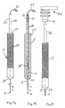
- FIGS. 1 and 2 shows, in section, a schematic representation of the electrode spiral 10 and the tension element 3, which is inserted into the inner lumen 4.
- a tension element head K is attached, to which at least two, but preferably three or four barbs 6 are fastened.
- the arrangement and design is such that these barbs 6, under the action of a permanent force, strive to spread outward.
- the tension element head K and the barbs 6 are preferably made of a plastic and are made in one piece. The shape can be designed such that the barbs are under a permanent spreading tension. Contrary to this voltage, when they are inserted into the electrode spiral, they attach themselves to the wall W thereof.
- the pull element 3 is provided with a handle 8 with a grip hole 9.
- the design can also be such that the tension element head K is not inseparably connected to the tension element 3 with its umbrella head 5, but that the connection is only non-positive and is released when a predetermined limit tensile force is exceeded; this limit tensile force can be such that injuries at the ingrowth of the patient's body are avoided.
- the device is inserted with the pulling element 3 in the insertion direction E into the inner lumen 4 of an electrode spiral 10, which is, for example, a cardiac catheter electrode exposed in the area of the pacemaker pocket.
- the pulling element 3 shown in FIGS. 3 to 6 consists of an inner wire 1 which is longitudinally displaceable in the pulling element sheath 2.
- the pulling element head K fastened to the pulling element sheath 2 is shifted into the area of the ingrowth location in the heart.
- FIGS. 3 and 4 there is a shielding chamber at the end of the tension element casing 2 11 attached, and at the end of the inner wire 1 there is a screen head 5 with screen-like barbs 6 attached to it, as can be seen from FIG. 3.
- the retaining ring 7 is attached, while the inner wire 1 is connected to the handle 8.
- the inner wire 1 is displaced with respect to the tension element jacket 2 and the shield head 5 with the barbs 6 attached thereto slides out of the shield chamber 1, the barbs 6 unfolding like an umbrella.
- FIGS. 5 and 6 A further modification is shown in FIGS. 5 and 6.
- the shielding chamber 11 is completely closed, but provided with the passage openings 13 assigned to each barb 6 or each expanding lug 16, which are arranged and designed such that after reaching the end position of the shielding head 5 in its most advanced position in the shielding chamber 11 and Subsequent reversal of movement of the inner wire 1 with respect to the tension element jacket 2, the barbs 6 (or spreading lugs 16) pass through the passage openings 13 and in this way are spread outwards and brought to bear against the wall W of the inner lumen 4. This is done, as shown in Figs. 3 and 4, due to the pressing on the Wall W whose deformation and the non-positive or positive connection with the electrode coil 10.
- a relative displacement of the inner wire 1 against the tension element jacket 2 against the pulling direction i.e. in direction E (FIG. 5)
- the spreading barbs 6 or spreading lugs 16 can be pulled back and the device to be pulled out by pulling on the retaining ring 7 or removed.
- the handle 8 can be provided with a device 21 - holding button and groove - by means of which a non-rotatable connection between the inner wire 1 - retaining ring 7 - and the tension element 3 - handle 8 - is exposed.
- the motor 20 can be connected to the handle 8 in such a way that the torque is transmitted to the tension element 3 and inner wire 1.
Abstract
Claims (11)
- Dispositif pour l'extraction d'électrodes de stimulation cardiaque introduites dans le coeur, apte à exercer une force de traction sur lesdites électrodes au moyen d'un élément de traction (3) introduit dans la cavité interne (4) d'une électrode en spirale (10) et équipé d'une tête de traction (K) capable de s'écarter ou de s'élargir, l'élément de traction (3) comportant un corps de traction (2) auquel est fixé la tête de traction (K) et dans lequel coulisse longitudinalement un fil intérieur (1), caractérisé en ce que la tête de traction (K) comporte au moins deux crochets (6) rapportés et écartables reliés à l'élément de traction (1) par une tête en pointe de parapluie (5), qui après un mouvement relatif entre l'élément de traction (1) et la tête de traction (K) s'accrochent dans la paroi (W) de la cavité interne (4) par marche arrière de l'élément de traction (3).
- Dispositif selon la revendication 1, caractérisé en ce que la tête de traction (K) comporte une chambre (11) pour la prise des crochets (6) qui sont libérables de la chambre par une pression de sortie exercée par le mouvement relatif entre l'élément de traction (1) et la tête de traction (K).
- Dispositif selon l'une des revendications 1 à 2 caractérisé en ce que la chambre (11) présente des fentes (13) dirigées selon l'axe (X) de la spirale pour le passage des crochets (6) ou des becs (16) accrochés à la tête en pointe de parapluie (5), lesquels peuvent sortir et s'écarter et à nouveau rentrer par les fentes suite au mouvement relatif entre élément de traction (1) et tête de traction (K).
- Dispositif selon l'une des revendications 1 à 3, caractérisé en ce que la tête en pointe de parapluie (5) est placée à l'extrémité de l'élément de traction (3) sans y être attachée.
- Dispositif selon l'une des revendications 1 à 4 caractérisé en ce que le fil intérieur (1) est fixé à une poignée (8), et le corps de traction (2) est fixé à un anneau support (7).
- Dispositif selon la revendication 5 caractérisé en ce que la poignée (8) présente un trou de préhension (9).
- Dispositif selon l'une des revendications 1 à 6, caractérisé en ce qu'un dispositif manuel pour exercer et transmettre un mouvement rotatif est fixé à l'extrémité active de l'élément de traction tel que le corps de traction (2).
- Dispositif selon l'une au moins des revendications 1 à 7, caractérisé en ce que des moyens (21) pour réaliser une liaison tournante entre l'élément de traction (3) et la cavité interne (4) sont prévus à proximité de l'extrémité active de l'élément de traction (3) et du fil intérieur (1).
- Dispositif selon l'une au moins des revendications 6 à 8 caractérisé en ce qu'un moteur (20) est fixé à l'extrémité active de l'élément de traction (3) et/ou du fil interne (1) pour exercer un mouvement rotatif.
- Dispositif selon les revendications 5 et 7 carcatérisé en ce que entre la poignée (8) et l'anneau support est prévue une liaison rotative.
- Dispositif selon la revendication 8 caractérisé en ce que la poignée (8) est équipée d'un dispositif d'accouplement (18) avec la tête d'accouplement (19) d'un moteur (20).
Applications Claiming Priority (3)
| Application Number | Priority Date | Filing Date | Title |
|---|---|---|---|
| DE4018681 | 1990-06-11 | ||
| DE4018681A DE4018681C2 (de) | 1990-06-11 | 1990-06-11 | Vorrichtung zur Extrahierung einer Herzschrittmacherelektrode |
| PCT/DE1991/000490 WO1991019532A1 (fr) | 1990-06-11 | 1991-06-10 | Procede et dispositif pour l'extraction de spirales d'electrodes introduites dans un organe du corps humain |
Publications (2)
| Publication Number | Publication Date |
|---|---|
| EP0533700A1 EP0533700A1 (fr) | 1993-03-31 |
| EP0533700B1 true EP0533700B1 (fr) | 1994-04-13 |
Family
ID=6408200
Family Applications (1)
| Application Number | Title | Priority Date | Filing Date |
|---|---|---|---|
| EP91910162A Revoked EP0533700B1 (fr) | 1990-06-11 | 1991-06-10 | Dispositif pour l'extraction de spirales d'electrodes introduites dans un organe du corps humain |
Country Status (3)
| Country | Link |
|---|---|
| EP (1) | EP0533700B1 (fr) |
| DE (2) | DE4018681C2 (fr) |
| WO (1) | WO1991019532A1 (fr) |
Families Citing this family (5)
| Publication number | Priority date | Publication date | Assignee | Title |
|---|---|---|---|---|
| SE9202746L (sv) * | 1992-09-23 | 1993-09-27 | Siemens Elema Ab | Anordning för explantation av en elektrodanordning |
| SE9303122D0 (sv) * | 1993-09-24 | 1993-09-24 | Siemens Elema Ab | Anordning för explantation av en elektrodanordning |
| US5423806A (en) * | 1993-10-01 | 1995-06-13 | Medtronic, Inc. | Laser extractor for an implanted object |
| FR2718345B1 (fr) * | 1994-04-11 | 1997-04-04 | Braun Celsa Sa | Poignée pour un coulissement relatif contrôlé d'une gaine et d'une tige et appareillage d'implantation d'un dispositif médical, tel qu'un filtre, utilisant une telle poignée. |
| DE19748455C1 (de) | 1997-11-03 | 1999-07-29 | Vascomed Kathetertech | Vorrichtung zum Herausziehen eines ein längliches Innenlumen aufweisenden Gegenstandes aus seiner Verankerung in einem Körper |
Family Cites Families (8)
| Publication number | Priority date | Publication date | Assignee | Title |
|---|---|---|---|---|
| US3754555A (en) * | 1971-10-05 | 1973-08-28 | G Schmitt | Controllable barbed intracardial electrode |
| US4136701A (en) * | 1977-12-09 | 1979-01-30 | Barton Steven A | Retractable stimulation electrode apparatus |
| US4582056A (en) * | 1983-03-30 | 1986-04-15 | Mccorkle Jr Charles E | Endocardial lead extraction apparatus and method |
| US4471777A (en) * | 1983-03-30 | 1984-09-18 | Mccorkle Jr Charles E | Endocardial lead extraction apparatus and method |
| US4574800A (en) * | 1984-12-07 | 1986-03-11 | Cordis Corporation | Implanted lead extractor |
| DE3708133A1 (de) * | 1987-03-13 | 1988-09-22 | Bisping Hans Juergen | Implantierbare elektrodensonde mit ausfahrbarer schraubelektrode |
| US4913164A (en) * | 1988-09-27 | 1990-04-03 | Intermedics, Inc. | Extensible passive fixation mechanism for lead assembly of an implantable cardiac stimulator |
| CA2001200C (fr) * | 1988-11-09 | 2000-12-19 | Louis Goode | Appareil pour extraire une structure allongee implantee dans les tissus biologiques |
-
1990
- 1990-06-11 DE DE4018681A patent/DE4018681C2/de not_active Expired - Fee Related
-
1991
- 1991-06-10 WO PCT/DE1991/000490 patent/WO1991019532A1/fr not_active Application Discontinuation
- 1991-06-10 DE DE59101396T patent/DE59101396D1/de not_active Expired - Fee Related
- 1991-06-10 EP EP91910162A patent/EP0533700B1/fr not_active Revoked
Also Published As
| Publication number | Publication date |
|---|---|
| DE4018681C2 (de) | 2000-09-21 |
| WO1991019532A1 (fr) | 1991-12-26 |
| EP0533700A1 (fr) | 1993-03-31 |
| DE59101396D1 (de) | 1994-05-19 |
| DE4018681A1 (de) | 1991-12-12 |
Similar Documents
| Publication | Publication Date | Title |
|---|---|---|
| EP0348692B1 (fr) | Dispositif pour l'introduction transveneuse ou artérielle a moyen d'un fil guide | |
| DE19610461C2 (de) | Katheter mit einem Einführschlauch | |
| DE69635402T2 (de) | Führungseinheit mit internem Führungsdraht aus einer Formgedächtnislegierung | |
| DE3521717C2 (de) | Korbfaßzange für ein Endoskop | |
| DE60019294T2 (de) | Elektrochirurgische sonde zur tumorbehandlung mit radiofrequenz | |
| DE19928901C2 (de) | Vorrichtung zum Herausziehen eines ein längliches Innenlumen aufweisenden Gegenstandes aus seiner Verankerung in einem Körper | |
| DE3714560C2 (fr) | ||
| EP2589348B1 (fr) | Dispositif destiné à l'explantation de dérivations d'électrodes | |
| DE3603344A1 (de) | Vorrichtung zum zertruemmern von steinen, insbesondere von nieren- und gallensteinen oder dgl. | |
| DE3906598C2 (fr) | ||
| EP0829242A1 (fr) | Dispositif de retrait d'une endoprothèse implantée | |
| EP0533700B1 (fr) | Dispositif pour l'extraction de spirales d'electrodes introduites dans un organe du corps humain | |
| EP2281600B1 (fr) | Dispositif de défibrillation d'un coeur | |
| EP3415197A1 (fr) | Fil électrode et système d'implantation d'un tel fil électrode | |
| CH658377A5 (de) | Mechanischer lithotriptor. | |
| DE3937594A1 (de) | Verfahren und vorrichtung zur extrahierung in einem koerperorgan eingewachsener elektrodenspiralen | |
| DE4115136A1 (de) | Greifsysteme fuer organwege | |
| DE894606C (de) | Vorrichtung zum Einfangen, Zerkleinern und Entfernen von Fremdkoerpern (Steinen, Konkrementen) aus Hohlraeumen des menschlichen Koerpers | |
| DE102008005378B4 (de) | Implantierbare bipolare Elektrode | |
| EP2082778B1 (fr) | Electrode bipolaire | |
| DE19937043A1 (de) | Medizinisches Instrument zur Schaffung eines Hohlraums für einen endoskopischen Eingriff sowie Verfahren zur Verwendung dieses medizinischen Instruments | |
| DE4013085A1 (de) | Ureterkatheter mit einfuehrungshuelse | |
| EP2475419B1 (fr) | Dispositif de neuromodulation sacrée | |
| DE102016105845A1 (de) | Elektrodenkopf für eine Herzschrittmacher- oder Defibrillator-Elektrode | |
| EP1487361B1 (fr) | Dispositif pour stabiliser une fracture dans un os long |
Legal Events
| Date | Code | Title | Description |
|---|---|---|---|
| PUAI | Public reference made under article 153(3) epc to a published international application that has entered the european phase |
Free format text: ORIGINAL CODE: 0009012 |
|
| 17P | Request for examination filed |
Effective date: 19920910 |
|
| AK | Designated contracting states |
Kind code of ref document: A1 Designated state(s): DE ES FR GB IT NL SE |
|
| 17Q | First examination report despatched |
Effective date: 19930526 |
|
| GRAA | (expected) grant |
Free format text: ORIGINAL CODE: 0009210 |
|
| AK | Designated contracting states |
Kind code of ref document: B1 Designated state(s): DE ES FR GB IT NL SE |
|
| PG25 | Lapsed in a contracting state [announced via postgrant information from national office to epo] |
Ref country code: ES Free format text: THE PATENT HAS BEEN ANNULLED BY A DECISION OF A NATIONAL AUTHORITY Effective date: 19940413 |
|
| REF | Corresponds to: |
Ref document number: 59101396 Country of ref document: DE Date of ref document: 19940519 |
|
| ITF | It: translation for a ep patent filed |
Owner name: STUDIO TORTA SOCIETA' SEMPLICE |
|
| GBT | Gb: translation of ep patent filed (gb section 77(6)(a)/1977) |
Effective date: 19940526 |
|
| ET | Fr: translation filed | ||
| PLBI | Opposition filed |
Free format text: ORIGINAL CODE: 0009260 |
|
| EAL | Se: european patent in force in sweden |
Ref document number: 91910162.6 |
|
| 26 | Opposition filed |
Opponent name: COOK PACEMAKER CORPORATION Effective date: 19950113 Opponent name: BIOTRONIK MESS- UND THERAPIEGERAETE GMBH & CO INGE Effective date: 19950111 |
|
| NLR1 | Nl: opposition has been filed with the epo |
Opponent name: COOK PACEMAKER CORPORATION Opponent name: BIOTRONIK MESS- UND THERAPIEGERAETE GMBH & CO INGE |
|
| PLAW | Interlocutory decision in opposition |
Free format text: ORIGINAL CODE: EPIDOS IDOP |
|
| APAC | Appeal dossier modified |
Free format text: ORIGINAL CODE: EPIDOS NOAPO |
|
| APAE | Appeal reference modified |
Free format text: ORIGINAL CODE: EPIDOS REFNO |
|
| APAC | Appeal dossier modified |
Free format text: ORIGINAL CODE: EPIDOS NOAPO |
|
| PLBQ | Unpublished change to opponent data |
Free format text: ORIGINAL CODE: EPIDOS OPPO |
|
| PLAB | Opposition data, opponent's data or that of the opponent's representative modified |
Free format text: ORIGINAL CODE: 0009299OPPO |
|
| R26 | Opposition filed (corrected) |
Opponent name: BIOTRONIK MESS- UND THERAPIEGERAETE GMBH & CO INGE Effective date: 19950111 |
|
| NLR1 | Nl: opposition has been filed with the epo |
Opponent name: COOK PACEMAKER CORPORATION Opponent name: BIOTRONIK MESS- UND THERAPIEGERAETE GMBH & CO INGE |
|
| PGFP | Annual fee paid to national office [announced via postgrant information from national office to epo] |
Ref country code: GB Payment date: 20010606 Year of fee payment: 11 |
|
| PGFP | Annual fee paid to national office [announced via postgrant information from national office to epo] |
Ref country code: DE Payment date: 20010621 Year of fee payment: 11 |
|
| PGFP | Annual fee paid to national office [announced via postgrant information from national office to epo] |
Ref country code: FR Payment date: 20010626 Year of fee payment: 11 |
|
| PGFP | Annual fee paid to national office [announced via postgrant information from national office to epo] |
Ref country code: SE Payment date: 20010627 Year of fee payment: 11 |
|
| PGFP | Annual fee paid to national office [announced via postgrant information from national office to epo] |
Ref country code: NL Payment date: 20010630 Year of fee payment: 11 |
|
| PLBQ | Unpublished change to opponent data |
Free format text: ORIGINAL CODE: EPIDOS OPPO |
|
| PLAB | Opposition data, opponent's data or that of the opponent's representative modified |
Free format text: ORIGINAL CODE: 0009299OPPO |
|
| R26 | Opposition filed (corrected) |
Opponent name: BIOTRONIK MESS- UND THERAPIEGERAETE GMBH & CO INGE Effective date: 19950111 |
|
| REG | Reference to a national code |
Ref country code: GB Ref legal event code: IF02 |
|
| APAC | Appeal dossier modified |
Free format text: ORIGINAL CODE: EPIDOS NOAPO |
|
| NLR1 | Nl: opposition has been filed with the epo |
Opponent name: COOK PACEMAKER CORPORATION Opponent name: BIOTRONIK MESS- UND THERAPIEGERAETE GMBH & CO INGE |
|
| APAC | Appeal dossier modified |
Free format text: ORIGINAL CODE: EPIDOS NOAPO |
|
| RDAH | Patent revoked |
Free format text: ORIGINAL CODE: EPIDOS REVO |
|
| RDAG | Patent revoked |
Free format text: ORIGINAL CODE: 0009271 |
|
| STAA | Information on the status of an ep patent application or granted ep patent |
Free format text: STATUS: PATENT REVOKED |
|
| 27W | Patent revoked |
Effective date: 20011225 |
|
| NLR2 | Nl: decision of opposition | ||
| APAH | Appeal reference modified |
Free format text: ORIGINAL CODE: EPIDOSCREFNO |
|
| PLAB | Opposition data, opponent's data or that of the opponent's representative modified |
Free format text: ORIGINAL CODE: 0009299OPPO |