EP0533700B1 - Device for extracting helical electrodes which have become embedded in body organs - Google Patents
Device for extracting helical electrodes which have become embedded in body organs Download PDFInfo
- Publication number
- EP0533700B1 EP0533700B1 EP91910162A EP91910162A EP0533700B1 EP 0533700 B1 EP0533700 B1 EP 0533700B1 EP 91910162 A EP91910162 A EP 91910162A EP 91910162 A EP91910162 A EP 91910162A EP 0533700 B1 EP0533700 B1 EP 0533700B1
- Authority
- EP
- European Patent Office
- Prior art keywords
- pulling element
- head
- handle
- inner wire
- barbs
- Prior art date
- Legal status (The legal status is an assumption and is not a legal conclusion. Google has not performed a legal analysis and makes no representation as to the accuracy of the status listed.)
- Revoked
Links
Images


Classifications
-
- A—HUMAN NECESSITIES
- A61—MEDICAL OR VETERINARY SCIENCE; HYGIENE
- A61N—ELECTROTHERAPY; MAGNETOTHERAPY; RADIATION THERAPY; ULTRASOUND THERAPY
- A61N1/00—Electrotherapy; Circuits therefor
- A61N1/02—Details
- A61N1/04—Electrodes
- A61N1/05—Electrodes for implantation or insertion into the body, e.g. heart electrode
- A61N1/056—Transvascular endocardial electrode systems
- A61N1/057—Anchoring means; Means for fixing the head inside the heart
- A61N2001/0578—Anchoring means; Means for fixing the head inside the heart having means for removal or extraction
Definitions
- the invention relates to a device for extracting a pacemaker electrode spiral that has grown into the heart by exerting a tensile force thereon with a pulling element that can be inserted into the inner lumen of the electrode spiral, with an expandable or expandable pulling element head, the pulling element consisting of a pulling element jacket with a pulling element head attached to it and a longitudinally displaceable inner wire therein consists.
- a frequently used method to remove non-functioning or infected pacemaker electrodes from the body is the so-called permanent tensile stress, in which the electrode is exposed in the pacemaker pocket and is subjected to a permanent tensile stress between 100 and 500 grams for hours and days until the electrode wears out Tissue growth dissolves.
- a weight acts as a tensile load on the electrode by means of a cable guide.
- a disadvantage of this method is that the continuous tensile load must often be applied over several days, with the patient having to linger on the pulling device and in bed.
- the aim of the invention is to make it easier to extract electrode spirals which have already been implanted, have grown in the heart, are not functional or are infected.
- the tensile force required for this should be exerted directly at the place of ingrowth, and an infection of the heart e.g. B. by germs such as z. B. can be caused by advancing the extraction device should be excluded.
- the invention has for its object to provide an easy-to-use extraction instrument that is easy to handle in the introductory phase, the pull-out phase and when the treatment is stopped by an operator and offers the patient the greatest possible safety when extracting .
- an extraction instrument provided with the features known from the cited preamble, which is characterized in that the pulling element head has at least two expandable barbs which are attached to an umbrella head connected to the pulling element and which, after relative displacement between the pulling element and Hook the tension element head into the wall of the inner lumen when the direction of movement of the tension element is reversed.
- this device means considerable relief for the doctor or surgeon and protection for the patient in physical and psychological terms.
- the extraction of ingrown electrodes is also carried out with greater certainty and simplicity according to the teaching according to the invention, because both targeted manipulations by hand are avoided and the outlay on equipment is largely eliminated.
- the traction element consists of a traction element jacket with a traction element head fastened to it and an inner wire which can be displaced longitudinally in the latter enables excellent manipulation of the device, because the inner wire allows certain adjustment and adjustment functions to be carried out.
- tension element head is provided with at least two barbs which can be extended by means of relative displacement of the inner wire and which are arranged on a screen head means that one and the same extraction instrument can be used in a large number of similar but different sized electrode spirals, which increases the safety and the success rate of the intervention .
- a particularly simple introduction of the instrument is given in a particularly advantageous variant, which is designed in such a way that the tension element head contains a chamber for receiving the at least two barbs attached to the umbrella head connected to the tension element and expandable, which after relative displacement between the tension element and The tension element head can be released by pushing it out of the chamber.
- the inner wire in the traction element makes it possible, above all, to activate the variously configurable elements and thus to bring them into connection with the inner wall of the electrode lumen in order to transmit the tractive force to the electrode at the desired locations.
- the extraction of the electrode spiral which has grown too strongly ingrown, can fail in the described manner in individual cases, so that the tension element is to be removed.
- a manually operable device for exerting and transmitting a torque can be connected to the operator-side end of the tension element or the tension element jacket, and, as a modification thereof, the Device be designed in such a way that devices for establishing a rotationally fixed connection between the tension element and the inner wire are arranged in the region of the operator-side ends of the tension element and the inner wire.
- a motor for transmitting a torque can be connected to the operator-side end of the tension element and / or the inner wire.
- the rotational movement between the tension element and the inner wire can also be provided that a rotationally fixed connection can be established between the handle and the retaining ring.
- the handle is provided with a coupling device for the motor provided with a coupling option.
- a handle and a retaining ring are provided, which are connected to the inner wire and the tension element jacket.
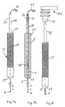
- FIGS. 1 and 2 shows, in section, a schematic representation of the electrode spiral 10 and the tension element 3, which is inserted into the inner lumen 4.
- a tension element head K is attached, to which at least two, but preferably three or four barbs 6 are fastened.
- the arrangement and design is such that these barbs 6, under the action of a permanent force, strive to spread outward.
- the tension element head K and the barbs 6 are preferably made of a plastic and are made in one piece. The shape can be designed such that the barbs are under a permanent spreading tension. Contrary to this voltage, when they are inserted into the electrode spiral, they attach themselves to the wall W thereof.
- the pull element 3 is provided with a handle 8 with a grip hole 9.
- the design can also be such that the tension element head K is not inseparably connected to the tension element 3 with its umbrella head 5, but that the connection is only non-positive and is released when a predetermined limit tensile force is exceeded; this limit tensile force can be such that injuries at the ingrowth of the patient's body are avoided.
- the device is inserted with the pulling element 3 in the insertion direction E into the inner lumen 4 of an electrode spiral 10, which is, for example, a cardiac catheter electrode exposed in the area of the pacemaker pocket.
- the pulling element 3 shown in FIGS. 3 to 6 consists of an inner wire 1 which is longitudinally displaceable in the pulling element sheath 2.
- the pulling element head K fastened to the pulling element sheath 2 is shifted into the area of the ingrowth location in the heart.
- FIGS. 3 and 4 there is a shielding chamber at the end of the tension element casing 2 11 attached, and at the end of the inner wire 1 there is a screen head 5 with screen-like barbs 6 attached to it, as can be seen from FIG. 3.
- the retaining ring 7 is attached, while the inner wire 1 is connected to the handle 8.
- the inner wire 1 is displaced with respect to the tension element jacket 2 and the shield head 5 with the barbs 6 attached thereto slides out of the shield chamber 1, the barbs 6 unfolding like an umbrella.
- FIGS. 5 and 6 A further modification is shown in FIGS. 5 and 6.
- the shielding chamber 11 is completely closed, but provided with the passage openings 13 assigned to each barb 6 or each expanding lug 16, which are arranged and designed such that after reaching the end position of the shielding head 5 in its most advanced position in the shielding chamber 11 and Subsequent reversal of movement of the inner wire 1 with respect to the tension element jacket 2, the barbs 6 (or spreading lugs 16) pass through the passage openings 13 and in this way are spread outwards and brought to bear against the wall W of the inner lumen 4. This is done, as shown in Figs. 3 and 4, due to the pressing on the Wall W whose deformation and the non-positive or positive connection with the electrode coil 10.
- a relative displacement of the inner wire 1 against the tension element jacket 2 against the pulling direction i.e. in direction E (FIG. 5)
- the spreading barbs 6 or spreading lugs 16 can be pulled back and the device to be pulled out by pulling on the retaining ring 7 or removed.
- the handle 8 can be provided with a device 21 - holding button and groove - by means of which a non-rotatable connection between the inner wire 1 - retaining ring 7 - and the tension element 3 - handle 8 - is exposed.
- the motor 20 can be connected to the handle 8 in such a way that the torque is transmitted to the tension element 3 and inner wire 1.
Abstract
Description
Die Erfindung betrifft eine Vorrichtung zur Extrahierung einer im Herzen eingewachsenen Herzschrittmacherelektrodenspirale durch Ausübung einer Zugkraft auf diese mit einem in das Innenlumen der Elektrodenspirale einführbaren Zugelement mit einem aufweitbaren oder aufspreizbaren Zugelementkopf, wobei das Zugelement aus einem Zugelementmantel mit daran befestigtem Zugelementkopf und einem in diesem längsverschiebbaren Innendraht besteht.The invention relates to a device for extracting a pacemaker electrode spiral that has grown into the heart by exerting a tensile force thereon with a pulling element that can be inserted into the inner lumen of the electrode spiral, with an expandable or expandable pulling element head, the pulling element consisting of a pulling element jacket with a pulling element head attached to it and a longitudinally displaceable inner wire therein consists.
Eine häufig angewandte Methode, um nichtfunktionierende oder infizierte Herzschrittmacherelektroden aus dem Körper zu entfernen ist die sogenannte Dauerzugbelastung, bei der die Elektrode in der Herzschrittmachertasche freigelegt wird und mit einer Dauerzugbelastung zwischen 100 bis 500 Gramm über Stunden und Tage beaufschlagt wird, bis sich die Elektrode aus Gewebeverwachsungen löst. Ein Gewicht wirkt mittels einer Seilführung als Zugbelastung auf die Elektrode.A frequently used method to remove non-functioning or infected pacemaker electrodes from the body is the so-called permanent tensile stress, in which the electrode is exposed in the pacemaker pocket and is subjected to a permanent tensile stress between 100 and 500 grams for hours and days until the electrode wears out Tissue growth dissolves. A weight acts as a tensile load on the electrode by means of a cable guide.
Nachteilig bei dieser Methode ist, daß die Dauerzugbelastung oft über mehrere Tage angewandt werden muß, wobei der Patient an der Zugvorrichtung und im Bett verweilen muß.A disadvantage of this method is that the continuous tensile load must often be applied over several days, with the patient having to linger on the pulling device and in bed.
Es ist ferner bekannt, zum Extrahieren nicht funktionierender oder infizierter, eingewachsener Herzschrittmacherelektroden einen Schlingenkatheter zu verwenden, wobei eine Schlinge über die Herzkatheterelektrode bis zum Einwachsungsort vorgeschoben und fixiert wird. Eine Zugkraft kann dann direkt vor Ort angewendet werden.It is also known to use a loop catheter to extract non-functioning or infected ingrown pacemaker electrodes, a loop being advanced and fixed over the cardiac catheter electrode to the site of ingrowth. A traction can then be applied directly on site.
Von Nachteil bei diesen bekannten und überwiegend angewandten Verfahrensweisen erscheint, daß ein Schlingenkatheter nicht bei infizierten Herzschrittmachertaschen oder Herzkatheterelektroden angewendet werden soll, da es beim Vorschieben des Schlingenkatheters über die Elektrode zu einer Keimverschleppung ins Herz kommen kann. Bei Anwendung der Dauerzugbelastung wird der Patient durch die erzwungene langdauernde Ruhehaltung im Bett psychisch und physisch in seinem Befinden schwer beeinträchtigt.A disadvantage of these known and predominantly used procedures appears that a loop catheter should not be used with infected pacemaker pockets or cardiac catheter electrodes, since germs can spread to the heart when the loop catheter is advanced over the electrode. When using the permanent train load, the patient is severely impaired mentally and physically by the forced long-term resting in bed.
Aus der US 4 574 800 ist eine Vorrichtung gemäß dem Oberbegriff des Anspruch 1 bekannt, bei der an dem Zugdraht eine Kugel befestigt ist, die, wenn sie zurückgezogen wird, den Zugelementmantel aufspreizt und so diesen mit der Elektrodenspirale verklemmt. Dann kann die gesamte Einheit mit der Elektrode zurückgezogen werden, Diese Vorrichtung weist den Nachteil auf, daß nach der erreichten Verklemmung eine Relativbewegung zwischen Zugelementmantel und Zugdraht ausgeschlossen werden muß, da sich ansonsten der Zugriff der Kugel lösen könnte. Dies führt zu einer schwer manipulierbaren Auszugseinrichtung mit entgegengesetzt zu bewegenden und haltenden Elementen.From US 4,574,800 a device according to the preamble of
Wird dagegen die Kugel derart verklemmt, daß sie unverrückbar sitzt, und damit in einfacherer Weise an dem Zugdraht und dem Zugmantel gezogen werden kann, entfällt die Möglichkeit, den Auszugsvorgang abzubrechen, da über die beiden Elemente Zugdraht und Zugmantel keine entsprechende Druckkraft mehr ausübbar ist, um die Kugel zu befreien. Dies ist um so mehr der Fall bei Benützung der alternativen Zugelementköpfe mit zylinddrischem Durchmesser.If, on the other hand, the ball is jammed in such a way that it sits immovably and can thus be pulled in a simpler manner on the puller wire and the pulling jacket, there is no possibility of interrupting the pull-out process, since no corresponding compressive force can be exerted via the two elements of the pulling wire and pulling jacket, to free the bullet. This is all the more the case when using the alternative tension element heads with a cylindrical diameter.
Aus der Research Disclosure, Nr. 299, März 1989, Seite 223 ist ein Extrahierungsinstrument bekannt, das über rückwärtig gerichtete Widerhaken verfügt, die durch abgeschrägte Ausnehmungen aus einem hypodermischen Schlauch gebildet worden sind. Diese Vorrichtung weist den Nachteil auf, daß sie in der Praxis nur schwer einsetzbar ist, da für ein effektives Greifen der Widerhaken der Durchmesser des Schlauches etwas größer als der Innendurchmesser des Lumens der Elektrodenspirale sein muß, so daß das Extrahierungsinstrument nur mit erheblichem, kaum aufzuwendenen Druck in die Elektrodenspirale einführbar ist.An extraction instrument is known from Research Disclosure, No. 299, March 1989, page 223, which has rearward-looking barbs which have been formed by chamfered recesses from a hypodermic tube. This device has the disadvantage that it is difficult to use in practice, since the diameter of the tube must be somewhat larger than the inside diameter of the lumen of the electrode coil for an effective gripping of the barbs, so that the extraction instrument can be used only with considerable, hardly any Pressure can be introduced into the electrode spiral.
Der Erfindung liegt das Ziel zugrunde, das Extrahieren von bereits implantierten, im Herzen eingewachsener, nichtfunktionsfähiger oder infizierter Elektrodenspiralen zu erleichtern. Die dazu erforderliche Zugkraft soll direkt am Einwachsungsort ausgeübt werden, und eine Infektion des Herzens z. B. durch Keimverschleppung, wie sie z. B. durch das Vorschieben der Extraktionsvorrichtung hervorgerufen werden kann, soll ausgeschlossen sein.The aim of the invention is to make it easier to extract electrode spirals which have already been implanted, have grown in the heart, are not functional or are infected. The tensile force required for this should be exerted directly at the place of ingrowth, and an infection of the heart e.g. B. by germs such as z. B. can be caused by advancing the extraction device should be excluded.
Ausgehend von dem oben genannten Stand der Technik liegt der Erfindung die Aufgabe zugrunde ein einfach zu benutzendes Extrahierungsinstrument anzugeben, daß in der Einführungsphase, der Auszugsphase und beim Abbruch der Behandlung durch einen Operateur leicht zu handhaben ist und für den Patienten eine größtmögliche Sicherheit beim Extrahieren bietet.Based on the above-mentioned prior art, the invention has for its object to provide an easy-to-use extraction instrument that is easy to handle in the introductory phase, the pull-out phase and when the treatment is stopped by an operator and offers the patient the greatest possible safety when extracting .
Zur erfinderischen Lösung dieser Aufgabe wird ein mit den aus dem zitierten Oberbegriff bekannten Merkmalen versehenes Extrahierungsinstrument vorgeschlagen, das dadurch gekennzeichnet ist, daß der Zugelementkopf über wenigstens zwei an einem mit dem Zugelement verbundenen Schirmkopf angebrachten, ausspreizbaren Widerhaken verfügt, die sich nach Relativverschiebung zwischen Zugelement und Zugelementkopf bei Bewegungsrichtungsumkehr des Zugelements in die Wandung des Innenlumens verhaken.To achieve this object, an extraction instrument provided with the features known from the cited preamble is proposed, which is characterized in that the pulling element head has at least two expandable barbs which are attached to an umbrella head connected to the pulling element and which, after relative displacement between the pulling element and Hook the tension element head into the wall of the inner lumen when the direction of movement of the tension element is reversed.
Die Benutzung dieser Vorrichtung nach der Erfindung bedeutet für den Arzt bzw. Chirurgen eine erhebliche Erleichterung und für den Patienten Schonung in physischer und psychischer Hinsicht. Die Extraktion eingewachsener Elektroden wird nach der erfindungsgemäßen Lehre auch mit größerer Sicherheit und Einfachheit durchgeführt, weil sowohl ungezielte Manipulationen von Hand vermieden werden und auch der apparative Aufwand weitgehend entfällt.The use of this device according to the invention means considerable relief for the doctor or surgeon and protection for the patient in physical and psychological terms. The extraction of ingrown electrodes is also carried out with greater certainty and simplicity according to the teaching according to the invention, because both targeted manipulations by hand are avoided and the outlay on equipment is largely eliminated.
Dadurch, daß das Zugelement aus einem Zugelementmantel mit daran befestigten Zugelementkopf und einem in diesem längsverschiebbaren Innendraht besteht wird eine hervorragende Manipulierbarkeit der Vorrichtung ermöglicht, weil der Innendraht die Ausführung von bestimmten Ein- und Verstellfunktionen gestattet.The fact that the traction element consists of a traction element jacket with a traction element head fastened to it and an inner wire which can be displaced longitudinally in the latter enables excellent manipulation of the device, because the inner wire allows certain adjustment and adjustment functions to be carried out.
Dadurch, daß der Zugelementkopf mit wenigstens zwei mittels Relativverschiebung des Innendrahtes ausstellbaren, an einem Schirmkopf angeordneten Widerhaken versehen ist, kann ein und dasselbe Extrahierungsinstrument bei einer Vielzahl von gleichartigen, aber unterschiedlich großen Elektrodenspiralen eingesetzt werden, womit sich die Sicherheit und die Erfolgsrate des Eingriffs erhöht.The fact that the tension element head is provided with at least two barbs which can be extended by means of relative displacement of the inner wire and which are arranged on a screen head means that one and the same extraction instrument can be used in a large number of similar but different sized electrode spirals, which increases the safety and the success rate of the intervention .
Eine besonders einfache Einführung des Instruments ist bei einer besonders vorteilhaften Variante gegeben, die in der Weise ausgebildet ist, daß der Zugelementkopf eine Kammer zur Aufnahme der wenigstens zwei an dem mit dem Zugelement verbundenen Schirmkopf angebrachten und ausspreizbaren Widerhaken enthält, die nach Relativverschiebung zwischen Zugelement und Zugelementkopf durch Herausdrücken aus der Kammer freigebbar sind.A particularly simple introduction of the instrument is given in a particularly advantageous variant, which is designed in such a way that the tension element head contains a chamber for receiving the at least two barbs attached to the umbrella head connected to the tension element and expandable, which after relative displacement between the tension element and The tension element head can be released by pushing it out of the chamber.
Schließlich ist es nach einem zusätzlichen Vorschlag möglich, diese letztere Ausbildungsform dadurch zu vervollkommnen, daß der Schirmkopf mit dem Ende des Zugelements lösbar angeordnet ist.Finally, according to an additional proposal, it is possible to perfect this latter embodiment in that the umbrella head is detachably arranged with the end of the pulling element.
Diese verschiedenen Ausbildungsformen, welche noch weitere Varianten und auch gewisse Verfeinerungen ermöglichen, beruhen auf einem der Grundgedanken der Erfindung, durch Einführung des Zugelements mit einem Zugelementkopf in das Innenlumen der Elektrode, diesen Zugelementkopf in der Weise auszubilden, daß er sich form- oder kraftschlüssig an die Innenwandung der Elektrodenspirale anlegt oder verklemmt bzw. ankrallt oder verhakt, wodurch eine zumindest soweit zugfeste Verbindung geschaffen wird, um dadurch eine individuell bemeßbare und ausübbare Zugkraft - von Hand - zum Ansatz zu bringen, und zwar diesen Ansatz in unmittelbarer Nähe der Einwachsstelle im Körper angreifen zu lassen.These various forms of training, which still allow further variants and also certain refinements, are based on one of the basic ideas of the invention, by introducing the pulling element with a pulling element head into the inner lumen of the electrode, to form this pulling element head in such a way that it is positive or non-positive the inner wall of the Electrode spiral creates or jams or claws or hooks, creating an at least as far tensile connection, in order to bring an individually measurable and exercisable traction - by hand - to approach, and to let this approach attack in the immediate vicinity of the waxing point in the body .
Durch den Innendraht in dem Zugelement ist es vor allem möglich, die verschiedenartig gestaltbaren Elemente zu aktivieren und damit zur Verbindung mit der Innenwandung des Elektrodenlumens zu bringen, um die Zugkraft an den gewünschten Stellen auf die Elektrode zu übertragen.The inner wire in the traction element makes it possible, above all, to activate the variously configurable elements and thus to bring them into connection with the inner wall of the electrode lumen in order to transmit the tractive force to the electrode at the desired locations.
Wie bereits erwähnt, kann in Einzelfällen das Extrahieren der zu stark eingewachsenen Elektrodenspirale auf die beschriebene Weise mißlingen, so daß das Zugelement entfernt werden soll. Dies gelingt nach der weiteren Erfindung durch Herausdrehen aus den Spiralwindungen der Elektrode, und zu diesem Zweck ist vorgesehen, daß an das bedienerseitige Ende des Zugelements bzw. des Zugelementmantels eine handbetätigbare Vorrichtung zur Ausübung und Übertragung eines Drehmoments anschließbar ist, und in Abwandlung hiervon kann die Vorrichtung in der Weise ausgebildet sein, daß im Bereich der bedienerseitigen Enden des Zugelements und des Innendrahtes Vorrichtungen zum Herstellen einer drehfesten Verbindung zwischen Zugelement und Innendraht angeordnet sind. Zusätzlich besteht die Möglichkeit, daß mit dem bedienerseitigen Ende des Zugelements und/oder des Innendrahtes ein Motor zur Übertragung eines Drehmoments anschließbar ist. Zur Synchronisierung der Drehbewegung zwischen dem Zugelement und dem Innendraht kann ferner vorgesehen sein, daß zwischen dem Griff und dem Haltering eine drehfeste Verbindung herstellbar ist. Weiterhin kann es zweckmäßig sein, wenn der Griff mit einer Ankuppelvorrichtung für den mit einer Kuppelmöglichkeit versehenen Motor versehen ist.As already mentioned, the extraction of the electrode spiral, which has grown too strongly ingrown, can fail in the described manner in individual cases, so that the tension element is to be removed. This is achieved according to the further invention by unscrewing from the spiral windings of the electrode, and for this purpose it is provided that a manually operable device for exerting and transmitting a torque can be connected to the operator-side end of the tension element or the tension element jacket, and, as a modification thereof, the Device be designed in such a way that devices for establishing a rotationally fixed connection between the tension element and the inner wire are arranged in the region of the operator-side ends of the tension element and the inner wire. In addition, there is the possibility that a motor for transmitting a torque can be connected to the operator-side end of the tension element and / or the inner wire. For synchronization the rotational movement between the tension element and the inner wire can also be provided that a rotationally fixed connection can be established between the handle and the retaining ring. Furthermore, it can be useful if the handle is provided with a coupling device for the motor provided with a coupling option.
Zur Bedienung der Vorrichtung sind ein Griff und ein Haltering vorgesehen, welche mit dem Innendraht und dem Zugelementmantel verbunden sind.To operate the device, a handle and a retaining ring are provided, which are connected to the inner wire and the tension element jacket.
Weitere Merkmale und Einzelheiten der Erfindung sind anhand der in der Zeichnung dargestellten Ausführungsbeispiele näher erläutert.Further features and details of the invention are explained in more detail with reference to the exemplary embodiments shown in the drawing.
Es zeigen:
- Fig. 1
- die Vorrichtung nach der Erfindung in der einfachsten Ausführung im Schnitt beim Einführen in die Elektrodenspirale,
- Fig. 2
- die Vorrichtung nach Fig. 1 verhakt in die Elektrodenspirale,
- Fig. 3
- die Vorrichtung in einer weiteren Ausführung beim Einführen in die Elektrodenspirale,
- Fig. 4
- die Vorrichtung nach Fig. 3 im Schnitt, verhakt in die Elektrodenspirale,
- Fig. 5
- die Vorrichtung in eine Abwandlung der Ausführung nach Fig. 4 im Schnitt in der Phase des Einführens des Zugelements, wenn die Spreiznasen oder Widerhaken noch eingefahren sind,
- Fig. 6
- die Vorrichtung gemäß Fig. 5 mit ausgefahrenen Spreiznasen,
- Fig. 7a/b
- eine vereinfachte Darstellung der Ausbildung für einen Motorantrieb zum Herausdrehen,
- Fig. 8
- einen Längsschnitt gemäß Fig. 7a.
- Fig. 1
- the simplest embodiment of the device according to the invention in section when it is inserted into the electrode spiral,
- Fig. 2
- 1 hooks into the electrode spiral,
- Fig. 3
- the device in a further embodiment when it is inserted into the electrode spiral,
- Fig. 4
- 3 in section, hooked into the electrode spiral,
- Fig. 5
- the device in a modification of the embodiment of FIG. 4 in section in phase the insertion of the tension element when the spreading lugs or barbs are still retracted,
- Fig. 6
- 5 with the spreading lugs extended,
- Fig. 7a / b
- a simplified representation of the training for a motor drive to unscrew,
- Fig. 8
- a longitudinal section according to FIG. 7a.
Die in den Fig. 1 und 2 dargestellte Ausführung der erfindungsgemäßen Vorrichtung zeigt im Schnitt in schematischer Darstellung die Elektrodenspirale 10 und das Zugelement 3, welches in das Innenlumen 4 eingeführt wird.The embodiment of the device according to the invention shown in FIGS. 1 and 2 shows, in section, a schematic representation of the
Am Ende des Zugelements 3 ist ein Zugelementkopf K angebracht, an welchem wenigstens zwei, vorzugsweise aber drei oder vier Widerhaken 6 befestigt sind. Die Anordnung und Ausbildung ist so getroffen, daß diese Widerhaken 6 unter der Wirkung einer permanent wirkenden Kraft das Bestreben haben, sich nach außen aufzuspreizen. Vorzugsweise sind der Zugelementkopf K und die Widerhaken 6 aus einem Kunststoff hergestellt und einstückig gearbeitet. Dabei kann die Formgestaltung derart ausgelegt sein, daß die Widerhaken unter einer permanent wirkenden Spreizspannung stehen. Entgegen dieser Spannung legen sie sich beim Einführen in die Elektrodenspirale an deren Wandung W an. Wird nun nach Erreichen der Endlage des Zugelementkopfes K in der Nähe des Einwachsungsorts der Elektrodenspirale durch Zug entgegen der Einführrichtung E in Richtung A bewegt, dann haken sich die Widerhaken 6 an der Wandung W des Innenlumens 4 der Elektrodenspirale ein und verkeilen sich, so daß eine Zugkraft auf die Elektrode ausgeübt werden kann. Zur Handhabung ist das Zugelement 3 mit einem Griff 8 mit Griffloch 9 versehen.At the end of the
Die Ausbildungsweise kann auch so getroffen sein, daß der Zugelementkopf K mit seinem Schirmkopf 5 nicht unlösbar mit dem Zugelement 3 verbunden ist, sondern daß die Verbindung nur kraftschlüssig ist und sich bei Überschreiten einer vorgesehenen Grenzzugkraft löst; diese Grenzzugkraft kann derart bemessen sein, daß Verletzungen an der Einwachsungsstelle des Körpers des Patienten vermieden werden.The design can also be such that the tension element head K is not inseparably connected to the
Die folgenden Ausführungen beziehen sich auf die Ausbildungsformen nach den Fig. 3 bis 6.The following statements relate to the training forms according to FIGS. 3 to 6.
Die Vorrichtung wird mit dem Zugelement 3 in Einführrichtung E in das Innenlumen 4 einer Elektrodenspirale 10 eingeführt, die beispielsweise eine im Bereich der Herzschrittmachertasche freigelegte Herzkatheterelektrode ist.The device is inserted with the pulling
Das aus Fig. 3 bis 6 ersichtliche Zugelement 3 besteht aus einem im Zugelementmantel 2 längsverschiebbaren Innendraht 1. Der am Zugelementmantel 2 befestigte Zugelementkopf K wird bis in den Bereich des Einwachsungsortes im Herz verschoben.The pulling
In der abgewandelter Ausführung nach den Fig. 3 und 4 ist am Ende des Zugelementmantels 2 eine Schirmkammer 11 angebracht, und am Ende des Innendrahtes 1 befindet sich ein Schirmkopf 5 mit an diesem befestigten schirmartigen Widerhaken 6, wie aus Fig. 3 ersichtlich. Am anderen Ende des Zugelementmantels 2 ist der Haltering 7 angebracht, während der Innendraht 1 mit dem Griff 8 verbunden ist. Durch Zueinanderbewegen von Haltering 7 und Griff 8 wird der Innendraht 1 gegenüber dem Zugelementmantel 2 verschoben und der Schirmkopf 5 mit den daran befestigten Widerhaken 6 gleitet aus der Schirmkammer 1 heraus, wobei sich die Widerhaken 6 schirmartig entfalten. Durch eine Bewegungsumkehr zwischen Innendraht 1 und Zugelementmantel 2 werden nun die an der Wandung W des Innenlumens 4 anliegenden Widerhaken 6 Widerstand finden und sich einhaken, so daß dadurch eine zugfeste Verbindung zwischen dem Zugelement 3 und der Elektrode 10 geschaffen und es ermöglicht wird, die letztere von Hand herauszuziehen.In the modified embodiment according to FIGS. 3 and 4 there is a shielding chamber at the end of the tension element casing 2 11 attached, and at the end of the
Eine weitere Abwandlung ist in den Fig. 5 und 6 dargestellt. Dort ist die Schirmkammer 11 völlig geschlossen, jedoch mit den jedem Widerhaken 6 bzw. jeder Spreiznase 16 zugeordneten Durchlaßöffnungen 13 versehen, die derart angeordnet und gestaltet sind, daß nach Erreichen der Endposition des Schirmkopfes 5 in seiner am weitesten vorgeschobenen Lage in der Schirmkammer 11 und anschließender Bewegungsumkehr des Innendrahtes 1 gegenüber dem Zugelementmantel 2 die Widerhaken 6 (bzw. Spreiznasen 16) durch die Durchlaßöffnungen 13 hindurchtreten und auf diese Weise nach außen gespreizt und zur Anlage an der Wand W des Innenlumens 4 gebracht werden. Darauf erfolgt, ebenso wie in den Fig. 3 und 4 gezeigt, infolge des Andrückens an die Wand W deren Verformung und die kraft- oder formschlüssige Verbindung mit der Elektrodenspirale 10.A further modification is shown in FIGS. 5 and 6. There, the shielding
Dabei kann nach einem wesentlichen Vorteil durch eine Relativverschiebung von Innendraht 1 gegen den Zugelementmantel 2 entgegen der Zugrichtung, also in Richtung E (Fig. 5), ein Zurückziehen der ausgespreizten Widerhaken 6 bzw. Spreiznasen 16 bewirkt und die Vorrichtung durch Zug am Haltering 7 herausgezogen bzw. entfernt werden. Außerdem besteht die weitere Möglichkeit, die Verbindung zwischen dem Innendraht 1 und dem Schirmkopf 5 derart auszubilden, daß sie sich bei Überschreiten eines Grenzwertes an Zugkraft löst.According to a significant advantage, a relative displacement of the
Wie aus den Fig. 7a, 7b und 8 ersichtlich ist, kann der Griff 8 mit einer Vorrichtung 21 - Halteknopf und Nut - versehen sein, mittels welcher eine drehfeste Verbindung zwischen dem Innendraht 1 - Haltering 7 - und dem Zugelement 3 - Griff 8 - herausstellbar ist. Mittels einer Ankuppelvorrichtung 18 und einer entsprechenden Kupplung 19 kann der Motor 20 mit dem Griff 8 derart verbunden werden, daß das Drehmoment auf Zugelement 3 und Innendraht 1 übertragen wird.As can be seen from FIGS. 7a, 7b and 8, the
Claims (11)
- Device for extracting a cardiac pacemaker electrode coil, which is embedded in the heart, by exerting a tensile force on this coil using a pulling element (3) which can be introduced into the inner lumen (4) of the electrode coil (10) and has a pulling element head (K) which can be widened or spread open, the pulling element (3) consisting of a pulling element casing (2), with pulling element head (K) secured thereon, and of an inner wire (1) which is longitudinally displaceable in this casing, characterized in that the pulling element head (K) has at least two barbs (6) which can be spread open and are arranged on a protective cap (5) connected to the pulling element (1), these barbs (6) being hooked into the wall (W) of the inner lumen (4) after relative displacement between pulling element (1) and pulling element head (K) upon the reversal of the direction of movement of the pulling element (3).
- Device according to Claim 1, characterized in that the pulling element head (K) comprises a chamber (11) for receiving the at least two barbs (6) which can be released by being pressed out from the chamber (11) after relative displacement between pulling element (1) and pulling element head (K).
- Device according to Claim 1 or Claim 2, characterized in that the chamber (11) has, directed in the axial direction (X) of the coil, openings (13) through which the spreading lugs (16) or barbs (6) arranged on the protective cap (5) can be pressed out and spread and once more drawn in upon relative displacement between pulling element (1) and pulling element head (K).
- Device according to one of Claims 1 to 3, characterized in that the protective cap (5) is arranged at the end of the pulling element (3) in such a way that it can be detached therefrom.
- Device according to one of Claims 1 to 4, characterized in that the inner wire (1) is attached to a handle (8) and the pulling element casing (2) is attached to a holding ring (7).
- Device according to Claim 5, characterized in that the handle (8) has a handle hole (9).
- Device according to one of Claims 1 to 6, characterized in that a manually activatable device for exerting and transmitting a torque can be connected to the operator end of the pulling element or pulling element casing (2).
- Device according to one or more of Claims 1 to 7, characterized in that devices (21) for producing a rotationally fixed connection between pulling element (3) and inner wire (4) are arranged in the area of the operator ends of the pulling element (3) and of the inner wire (1).
- Device according to at least one of Claims 6 to 8, characterized in that a motor (20) for transmitting a torque can be connected to the operator end of the pulling element (3) and/or the inner wire (1).
- Device according to Claim 5 and 7, characterized in that a rotationally fixed connection can be produced between the handle (8) and the holding ring.
- Device according to Claim 8, characterized in that the handle (8) is provided with a coupling device (18) for the motor (20) which is provided with a coupling possibility (19).
Applications Claiming Priority (3)
| Application Number | Priority Date | Filing Date | Title |
|---|---|---|---|
| DE4018681A DE4018681C2 (en) | 1990-06-11 | 1990-06-11 | Device for extracting a pacemaker electrode |
| DE4018681 | 1990-06-11 | ||
| PCT/DE1991/000490 WO1991019532A1 (en) | 1990-06-11 | 1991-06-10 | Process and device for extracting helical electrodes which have become embedded in body organs |
Publications (2)
| Publication Number | Publication Date |
|---|---|
| EP0533700A1 EP0533700A1 (en) | 1993-03-31 |
| EP0533700B1 true EP0533700B1 (en) | 1994-04-13 |
Family
ID=6408200
Family Applications (1)
| Application Number | Title | Priority Date | Filing Date |
|---|---|---|---|
| EP91910162A Revoked EP0533700B1 (en) | 1990-06-11 | 1991-06-10 | Device for extracting helical electrodes which have become embedded in body organs |
Country Status (3)
| Country | Link |
|---|---|
| EP (1) | EP0533700B1 (en) |
| DE (2) | DE4018681C2 (en) |
| WO (1) | WO1991019532A1 (en) |
Families Citing this family (5)
| Publication number | Priority date | Publication date | Assignee | Title |
|---|---|---|---|---|
| SE469818B (en) * | 1992-09-23 | 1993-09-27 | Siemens Elema Ab | Device for explantation of an electrode device |
| SE9303122D0 (en) * | 1993-09-24 | 1993-09-24 | Siemens Elema Ab | Device for explantation of an electrode device |
| US5423806A (en) * | 1993-10-01 | 1995-06-13 | Medtronic, Inc. | Laser extractor for an implanted object |
| FR2718345B1 (en) * | 1994-04-11 | 1997-04-04 | Braun Celsa Sa | Handle for controlled relative sliding of a sheath and a rod and apparatus for implanting a medical device, such as a filter, using such a handle. |
| DE19748455C1 (en) * | 1997-11-03 | 1999-07-29 | Vascomed Kathetertech | Device for pulling an object having an elongated inner lumen out of its anchoring in a body |
Family Cites Families (8)
| Publication number | Priority date | Publication date | Assignee | Title |
|---|---|---|---|---|
| US3754555A (en) * | 1971-10-05 | 1973-08-28 | G Schmitt | Controllable barbed intracardial electrode |
| US4136701A (en) * | 1977-12-09 | 1979-01-30 | Barton Steven A | Retractable stimulation electrode apparatus |
| US4471777A (en) * | 1983-03-30 | 1984-09-18 | Mccorkle Jr Charles E | Endocardial lead extraction apparatus and method |
| US4582056A (en) * | 1983-03-30 | 1986-04-15 | Mccorkle Jr Charles E | Endocardial lead extraction apparatus and method |
| US4574800A (en) * | 1984-12-07 | 1986-03-11 | Cordis Corporation | Implanted lead extractor |
| DE3708133A1 (en) * | 1987-03-13 | 1988-09-22 | Bisping Hans Juergen | IMPLANTABLE ELECTRODE PROBE WITH EXTENDABLE SCREW ELECTRODE |
| US4913164A (en) * | 1988-09-27 | 1990-04-03 | Intermedics, Inc. | Extensible passive fixation mechanism for lead assembly of an implantable cardiac stimulator |
| CA2001200C (en) * | 1988-11-09 | 2000-12-19 | Louis Goode | Apparatus for removing an elongated structure implanted in biological tissue |
-
1990
- 1990-06-11 DE DE4018681A patent/DE4018681C2/en not_active Expired - Fee Related
-
1991
- 1991-06-10 EP EP91910162A patent/EP0533700B1/en not_active Revoked
- 1991-06-10 WO PCT/DE1991/000490 patent/WO1991019532A1/en not_active Application Discontinuation
- 1991-06-10 DE DE59101396T patent/DE59101396D1/en not_active Expired - Fee Related
Also Published As
| Publication number | Publication date |
|---|---|
| DE4018681A1 (en) | 1991-12-12 |
| DE4018681C2 (en) | 2000-09-21 |
| WO1991019532A1 (en) | 1991-12-26 |
| EP0533700A1 (en) | 1993-03-31 |
| DE59101396D1 (en) | 1994-05-19 |
Similar Documents
| Publication | Publication Date | Title |
|---|---|---|
| EP0348692B1 (en) | Device for entering a vein or artery by means of a guide wire | |
| DE19610461C2 (en) | Catheter with an insertion tube | |
| DE69635402T2 (en) | Guide unit with internal guidewire made of a shape memory alloy | |
| DE3521717C2 (en) | Basket forceps for an endoscope | |
| DE60019294T2 (en) | ELECTRO-SURGICAL PROBE FOR TUMOR TREATMENT WITH RADIO FREQUENCY | |
| DE19928901C2 (en) | Device for pulling an object having an elongated inner lumen out of its anchoring in a body | |
| DE3714560C2 (en) | ||
| EP2589348B1 (en) | Device for explanting electrode leads | |
| DE3603344A1 (en) | DEVICE FOR CRUSHING STONES, ESPECIALLY KIDNEY AND GALLET STONES OR THE LIKE | |
| DE3906598C2 (en) | ||
| EP0829242A1 (en) | Removal device for an implanted endoprothesis | |
| EP0533700B1 (en) | Device for extracting helical electrodes which have become embedded in body organs | |
| EP2281600B1 (en) | Device for defibrillating a heart | |
| EP3415197A1 (en) | Electrode wire and a system for implanting such an electrode wire | |
| CH658377A5 (en) | MECHANICAL LITHOTRIPTOR. | |
| DE3937594A1 (en) | Extracting spiral electrode from organ of human body - inserting thin drawing element in internal lumen of spiral until nearly reaching electrode head | |
| DE4115136A1 (en) | Removing body from blood vessel - using surgical instrument which consists of flexible wire with three hooks formed at one end | |
| DE894606C (en) | Device for catching, crushing and removing foreign bodies (stones, concrements) from cavities in the human body | |
| DE102008005378B4 (en) | Implantable bipolar electrode | |
| EP2082778B1 (en) | Bipolar electrode | |
| DE19937043A1 (en) | Medical instrument for creating a cavity for an endoscopic procedure and method for using this medical instrument | |
| DE4013085A1 (en) | Ureter catheter with guide sleeve - has slider to enable sleeve to be removed after catheter has been inserted | |
| EP2475419B1 (en) | Sacral neuromodulator | |
| DE102016105845A1 (en) | Electrode head for a pacemaker or defibrillator electrode | |
| EP1487361B1 (en) | Device for stabilising a break in a tubular bone |
Legal Events
| Date | Code | Title | Description |
|---|---|---|---|
| PUAI | Public reference made under article 153(3) epc to a published international application that has entered the european phase |
Free format text: ORIGINAL CODE: 0009012 |
|
| 17P | Request for examination filed |
Effective date: 19920910 |
|
| AK | Designated contracting states |
Kind code of ref document: A1 Designated state(s): DE ES FR GB IT NL SE |
|
| 17Q | First examination report despatched |
Effective date: 19930526 |
|
| GRAA | (expected) grant |
Free format text: ORIGINAL CODE: 0009210 |
|
| AK | Designated contracting states |
Kind code of ref document: B1 Designated state(s): DE ES FR GB IT NL SE |
|
| PG25 | Lapsed in a contracting state [announced via postgrant information from national office to epo] |
Ref country code: ES Free format text: THE PATENT HAS BEEN ANNULLED BY A DECISION OF A NATIONAL AUTHORITY Effective date: 19940413 |
|
| REF | Corresponds to: |
Ref document number: 59101396 Country of ref document: DE Date of ref document: 19940519 |
|
| ITF | It: translation for a ep patent filed |
Owner name: STUDIO TORTA SOCIETA' SEMPLICE |
|
| GBT | Gb: translation of ep patent filed (gb section 77(6)(a)/1977) |
Effective date: 19940526 |
|
| ET | Fr: translation filed | ||
| PLBI | Opposition filed |
Free format text: ORIGINAL CODE: 0009260 |
|
| EAL | Se: european patent in force in sweden |
Ref document number: 91910162.6 |
|
| 26 | Opposition filed |
Opponent name: COOK PACEMAKER CORPORATION Effective date: 19950113 Opponent name: BIOTRONIK MESS- UND THERAPIEGERAETE GMBH & CO INGE Effective date: 19950111 |
|
| NLR1 | Nl: opposition has been filed with the epo |
Opponent name: COOK PACEMAKER CORPORATION Opponent name: BIOTRONIK MESS- UND THERAPIEGERAETE GMBH & CO INGE |
|
| PLAW | Interlocutory decision in opposition |
Free format text: ORIGINAL CODE: EPIDOS IDOP |
|
| APAC | Appeal dossier modified |
Free format text: ORIGINAL CODE: EPIDOS NOAPO |
|
| APAE | Appeal reference modified |
Free format text: ORIGINAL CODE: EPIDOS REFNO |
|
| APAC | Appeal dossier modified |
Free format text: ORIGINAL CODE: EPIDOS NOAPO |
|
| PLBQ | Unpublished change to opponent data |
Free format text: ORIGINAL CODE: EPIDOS OPPO |
|
| PLAB | Opposition data, opponent's data or that of the opponent's representative modified |
Free format text: ORIGINAL CODE: 0009299OPPO |
|
| R26 | Opposition filed (corrected) |
Opponent name: BIOTRONIK MESS- UND THERAPIEGERAETE GMBH & CO INGE Effective date: 19950111 |
|
| NLR1 | Nl: opposition has been filed with the epo |
Opponent name: COOK PACEMAKER CORPORATION Opponent name: BIOTRONIK MESS- UND THERAPIEGERAETE GMBH & CO INGE |
|
| PGFP | Annual fee paid to national office [announced via postgrant information from national office to epo] |
Ref country code: GB Payment date: 20010606 Year of fee payment: 11 |
|
| PGFP | Annual fee paid to national office [announced via postgrant information from national office to epo] |
Ref country code: DE Payment date: 20010621 Year of fee payment: 11 |
|
| PGFP | Annual fee paid to national office [announced via postgrant information from national office to epo] |
Ref country code: FR Payment date: 20010626 Year of fee payment: 11 |
|
| PGFP | Annual fee paid to national office [announced via postgrant information from national office to epo] |
Ref country code: SE Payment date: 20010627 Year of fee payment: 11 |
|
| PGFP | Annual fee paid to national office [announced via postgrant information from national office to epo] |
Ref country code: NL Payment date: 20010630 Year of fee payment: 11 |
|
| PLBQ | Unpublished change to opponent data |
Free format text: ORIGINAL CODE: EPIDOS OPPO |
|
| PLAB | Opposition data, opponent's data or that of the opponent's representative modified |
Free format text: ORIGINAL CODE: 0009299OPPO |
|
| R26 | Opposition filed (corrected) |
Opponent name: BIOTRONIK MESS- UND THERAPIEGERAETE GMBH & CO INGE Effective date: 19950111 |
|
| REG | Reference to a national code |
Ref country code: GB Ref legal event code: IF02 |
|
| APAC | Appeal dossier modified |
Free format text: ORIGINAL CODE: EPIDOS NOAPO |
|
| NLR1 | Nl: opposition has been filed with the epo |
Opponent name: COOK PACEMAKER CORPORATION Opponent name: BIOTRONIK MESS- UND THERAPIEGERAETE GMBH & CO INGE |
|
| APAC | Appeal dossier modified |
Free format text: ORIGINAL CODE: EPIDOS NOAPO |
|
| RDAH | Patent revoked |
Free format text: ORIGINAL CODE: EPIDOS REVO |
|
| RDAG | Patent revoked |
Free format text: ORIGINAL CODE: 0009271 |
|
| STAA | Information on the status of an ep patent application or granted ep patent |
Free format text: STATUS: PATENT REVOKED |
|
| 27W | Patent revoked |
Effective date: 20011225 |
|
| NLR2 | Nl: decision of opposition | ||
| APAH | Appeal reference modified |
Free format text: ORIGINAL CODE: EPIDOSCREFNO |
|
| PLAB | Opposition data, opponent's data or that of the opponent's representative modified |
Free format text: ORIGINAL CODE: 0009299OPPO |