EP0531987B2 - Electrical heating unit - Google Patents
Electrical heating unit Download PDFInfo
- Publication number
- EP0531987B2 EP0531987B2 EP92115467A EP92115467A EP0531987B2 EP 0531987 B2 EP0531987 B2 EP 0531987B2 EP 92115467 A EP92115467 A EP 92115467A EP 92115467 A EP92115467 A EP 92115467A EP 0531987 B2 EP0531987 B2 EP 0531987B2
- Authority
- EP
- European Patent Office
- Prior art keywords
- temperature
- heaters
- switching
- heating unit
- heater
- Prior art date
- Legal status (The legal status is an assumption and is not a legal conclusion. Google has not performed a legal analysis and makes no representation as to the accuracy of the status listed.)
- Expired - Lifetime
Links
Images

Classifications
-
- F—MECHANICAL ENGINEERING; LIGHTING; HEATING; WEAPONS; BLASTING
- F24—HEATING; RANGES; VENTILATING
- F24C—DOMESTIC STOVES OR RANGES ; DETAILS OF DOMESTIC STOVES OR RANGES, OF GENERAL APPLICATION
- F24C15/00—Details
- F24C15/10—Tops, e.g. hot plates; Rings
- F24C15/102—Tops, e.g. hot plates; Rings electrically heated
- F24C15/106—Tops, e.g. hot plates; Rings electrically heated electric circuits
-
- G—PHYSICS
- G05—CONTROLLING; REGULATING
- G05D—SYSTEMS FOR CONTROLLING OR REGULATING NON-ELECTRIC VARIABLES
- G05D23/00—Control of temperature
- G05D23/19—Control of temperature characterised by the use of electric means
- G05D23/1927—Control of temperature characterised by the use of electric means using a plurality of sensors
- G05D23/193—Control of temperature characterised by the use of electric means using a plurality of sensors sensing the temperaure in different places in thermal relationship with one or more spaces
- G05D23/1932—Control of temperature characterised by the use of electric means using a plurality of sensors sensing the temperaure in different places in thermal relationship with one or more spaces to control the temperature of a plurality of spaces
- G05D23/1934—Control of temperature characterised by the use of electric means using a plurality of sensors sensing the temperaure in different places in thermal relationship with one or more spaces to control the temperature of a plurality of spaces each space being provided with one sensor acting on one or more control means
-
- H—ELECTRICITY
- H05—ELECTRIC TECHNIQUES NOT OTHERWISE PROVIDED FOR
- H05B—ELECTRIC HEATING; ELECTRIC LIGHT SOURCES NOT OTHERWISE PROVIDED FOR; CIRCUIT ARRANGEMENTS FOR ELECTRIC LIGHT SOURCES, IN GENERAL
- H05B3/00—Ohmic-resistance heating
- H05B3/68—Heating arrangements specially adapted for cooking plates or analogous hot-plates
-
- Y—GENERAL TAGGING OF NEW TECHNOLOGICAL DEVELOPMENTS; GENERAL TAGGING OF CROSS-SECTIONAL TECHNOLOGIES SPANNING OVER SEVERAL SECTIONS OF THE IPC; TECHNICAL SUBJECTS COVERED BY FORMER USPC CROSS-REFERENCE ART COLLECTIONS [XRACs] AND DIGESTS
- Y02—TECHNOLOGIES OR APPLICATIONS FOR MITIGATION OR ADAPTATION AGAINST CLIMATE CHANGE
- Y02B—CLIMATE CHANGE MITIGATION TECHNOLOGIES RELATED TO BUILDINGS, e.g. HOUSING, HOUSE APPLIANCES OR RELATED END-USER APPLICATIONS
- Y02B30/00—Energy efficient heating, ventilation or air conditioning [HVAC]
- Y02B30/70—Efficient control or regulation technologies, e.g. for control of refrigerant flow, motor or heating
Abstract
Description
Die Erfindung betrifft eine elektrische Heizeinheit nach dem Oberbegriff des Patentanspruches 1. Sie soll insbesondere für eine Kochstelle oder andere zu beheizende Bereiche geeignet sein, bei welchen durch Wärmeleitung und/oder Strahlung Wärmeenergie im Bereich einer Heizfläche abgegeben werden soll.The invention relates to an electric heating unit according to the preamble of claim 1. You should especially for a hotplate or other to be heated Areas may be suitable in which heat conduction and / or radiation thermal energy in the area to be given to a heating surface.
Bei solchen Heizeinheiten, z.B. Elektro-Kochplatten, kann erfindungsgemäß eine Temperaturregelung oder -steuerung der von gesonderten Heizwiderständen aufgenommenen bzw. abgegebenen Leistungen vorgesehen sein. Hierzu kann ein Temperaturfühler im ringförmig beheizten Bereich, im unbeheizten Zentrum oder an anderer Stelle unmittelbar der Strahlung mindestens eines Heizwiderstandes und/oder eines Heiz- bzw.With such heating units, e.g. Electric hotplates, can according to the invention a temperature control or control of separate heating resistors services added or given be provided. For this purpose, a temperature sensor in the annularly heated area, in the unheated center or at least elsewhere directly the radiation a heating resistor and / or a heating respectively.
Kochplattenkörpers ausgesetzt sein und bei Erreichen einer bestimmten, manuell eingestellten Temperatur die Leistung mindestens eines Heizwiderstandes teilweise oder ganz abschalten sowie nach Erreichen einer unteren Grenztemperatur wieder einschalten. Ist ein Leistungssteuergerät vorgesehen, so schaltet dieses die genannte Leistung periodisch ein und aus, wobei die relative Einschaltzeit mit höher eingestellter Temperatur zunimmt.Hotplate body exposed and when reached a certain, manually set temperature the performance of at least one heating resistor switch off partially or completely and after reaching switch on again at a lower limit temperature. is a power control device is provided, this switches the specified power periodically on and off, whereby the relative switch-on time with a higher one Temperature increases.
Besonders bei hoher Leistungsabnahme, wie sie z. B. beim Aufheizen großer Wassermengen gegeben ist, können die Schaltvorgänge der Regelung bzw. Steuerung zu nachteiligen Schaltimpulsen und insbesondere einer unzulässigen Knackrate führen. Die Entnahme der Wärmeenergie kann ferner in unterschiedlichen Flächenbereichen der Heizfläche unterschiedlich sein und auch wechseln, wodurch sich eine gewünschte unterschiedliche oder gleichmäßige Temperaturverteilung über die Fläche unerwünscht ändert, ohne daß Möglichkeiten gegeben sind, diesen Veränderungen entgegen zu steuern. Im Falle eines Kochgefäßes liegt meist der Boden im Bereich des Außenumfanges berührend an der Koch- bzw. Heizfläche an, während er im Zentrum berührungsfrei ist, so daß in diesem Bereich die Heizfläche mangels guten Wärmeüberganges in der Temperatur stark ansteigt.Especially with high power consumption, as z. B. is given when heating large amounts of water, can the switching processes of regulation or control to disadvantageous switching impulses and in particular lead to an inadmissible click rate. The withdrawal the thermal energy can also be in different areas the heating surface must be different and also switch, which makes a desired different or even temperature distribution undesirably changes across the area without any possibilities given these changes to control. In the case of a cooking vessel, this is usually the case Touching the floor in the area of the outer circumference the cooking or heating surface while it is in the center is non-contact, so that the heating surface in this area lack of good heat transfer in the temperature rises sharply.
Die GB-A-2 067 857 betrifft eine Heizeinheit, bei welcher zwei Heizungen aneinanderschließend so umgeschaltet werden, daß bei Betrieb der einen die andere außer Betrieb ist.GB-A-2 067 857 relates to a heating unit at which switched two heaters in such a way be that when one is operating the other is out of order.
Die DE-A 3 810 586 zeigt eine Zweikreis-Beheizung mit Temperaturfühlern, welche als Überhitzungsschutz dienen.DE-A 3 810 586 shows a two-circuit heating with temperature sensors, which protect against overheating serve.
Die DE-A35 39 581 zeigt ein Verfahren zum Steuern elestrischer Heizungen eines Elektroherdes. Um Netzrückwirkungen zu verringern werden dort die Lasten zeitlich aneinandergekettet innerhalb einer Taktzeit an das Netz geschaltet.DE-A35 39 581 shows a method for controlling electrical power Electric stove heaters. To reduce network interference the loads are chained together within there switched to the network at one cycle time.
Der Erfindung liegt die Aufgabe zugrunde, eine Heizeinheit zu schaffen, bei welcher Nachteile bekannter Ausbildungen oder der beschriebenen Art vermieden sind und die insbesondere eine gegenseitige relative Anpassung der Temperatur in gesonderten Flächenbereichen der Heizfläche ermöglicht.The invention has for its object a To create heating unit, at which disadvantages are known Avoid training or the type described are and in particular a mutual relative Adjustment of the temperature in separate areas of the heating surface.
Erfindungsgemäß sind die Merkmale nach Patentanspruch 1 vorgesehen. Es können zwei oder mehr benachbarte, aneinanderschließende, ineinanderübergehende und/oder innerhalb einer gemeinsamen Umfangsbegrenzung der Heizfläche liegende Flächenbereiche gesondert geregelt werden. Dadurch kann die Temperatur bzw. die Heizleistung für jeden dieser Flächenbereiche z.B. daran angepaßt werden, wieviel Wärmeenergie dem jeweiligen Flächenbereich im Verhältnis zu mindestens einem anderen Flächenbereich entnommen wird. Ändert sich dieses Verhältnis im Laufe der Zeit, so kann die Temperaturregelung nachfolgen. Dadurch ist es sowohl möglich, die beiden Flächenbereiche im wesentlichen unabhängig von der Wärmeentnahme bei gleicher Temperatur oder auf einer gewünschten Temperaturdifferenz zu halten, die z.B. zeitund/oder temperaturabhängig verändert werden kann.According to the invention, the features according to claim 1 provided. Two or more neighboring, contiguous, merging and / or within a common perimeter areas of the heating surface to be regulated separately. This allows the Temperature or the heating power for each of these surface areas e.g. be adjusted to how much Thermal energy in relation to the respective area to at least one other area is removed. This ratio changes over the course of time, the temperature control can follow. This makes it possible to use both surface areas essentially independent of heat extraction at the same temperature or at a desired one To keep the temperature difference, e.g. time- and / or can be changed depending on the temperature.
Zweckmäßig erfolgt die Temperaturregelung nicht durch eine Änderung der thermischen Ankopplung der Flächenbereiche, sondern durch eine Änderung der den zugehörigen Heizungen zugeführten Leistung, insbesondere der zugeführten elektrischen Leistung. Ferner wird dadurch erreicht, daß die gewünschte Temperaturdifferenz zwischen den Flächenbereichen durch gegenläufiges Regeln beider Flächenbereiche schneller erzielt wird.The temperature control is expediently not carried out by changing the thermal coupling of the Areas, but by changing the power supplied to associated heaters, in particular the electrical power supplied. Further is achieved in that the desired temperature difference between the surface areas contrary regulation of both surface areas faster is achieved.
Erfindungsgemäß wird wenigstens ein bestimmter Leistungsbetrag periodisch und wechselweise auf mindestens zwei Flächenbereiche umgeschaltet. Bei Betrieb mit Wechselstrom ist dabei die längste Periodendauer vorteilhaft wesentlich kürzer als eine Sekunde oder eine halbe Sekunde. Die Umschaltung erfolgt im Augenblick des Durchganges der wellenförmigen Wechselstrom-Kennlinie durch die mittlere Null-Linie, so daß keine Störimpulse auftreten. Erfolgt dabei der Einschaltvorgang für den einen Flächenbereich praktisch zeitgleich mit dem Ausschaltvorgang für den anderen Flächenbereich, so ergibt sich keinerlei Unterbrechung in der von der Stromquelle abgenommenen Leistung, so daß der Umschaltvorgang keinerlei Knackimpulse verursacht.According to the invention, at least one is determined Benefit amount periodically and alternately to at least switched two surface areas. In operation with alternating current is the longest period advantageously much shorter than a second or half a second. The switchover takes place in Moment of passage of the wavy AC characteristic curve through the middle zero line, so that no interference pulses occur. If the Switching on for one area is practical at the same time as the switch-off process for the other Area, there is no interruption in the power drawn from the power source, so that the switching process has no clicks caused.
Dies wird noch weiter verbessert, wenn die Heizungen, zwischen denen umgeschaltet wird, im wesentlichen gleiche Aufnahme- bzw. Nennleistung haben. Bei einer Umschaltung zwischen mindestens zwei Heizungen bzw. Heizkreisen können z. B. die Zeitintervalle der Leistungszufuhr für alle Heizungen etwa gleich groß gewählt werden, so daß alle Heizungen im wesentlichen mit einem gleichen Prozentanteil zur gesamten Heizleistung der Heizfläche beitragen. Ergibt sich durch geringere Wärmeentnahme im Heizbereich einer Heizung ein entsprechender Temperaturanstieg, so wird dieser durch Temperaturfühlung erfaßt und es wird durch eine selbstätig bzw. temperaturabhängig arbeitende Steuerung die Dauer der Zeitintervalle der Leistungszufuhr zu dieser Heizung verringert, während die entsprechende Dauer für mindestens eine weitere Heizung erhöht wird, bis sich die einer Justierung entsprechende Temperaturverteilung wieder eingestellt hat. Z. B. können von 20 Vollwellen der Wechselstrom-Kennlinie in einem solchen Fall fünf Vollwellen je Zeitintervall an die Heizung des wärmeren Bereiches und 15 Vollwellen an die Heizung des kälteren Bereiches gegeben werden, was einer Leistungsaufteilung von 25% zu 75% entspricht. Da bei Wechselstrom mit 50 Hertz 50 Vollwellen zur Verfügung stehen, beträgt das kürzere Zeitintervall nur 1/10 Sekunde, während das längere Zeitintervall etwa 1/3 Sekunde entspricht. Sobald die gewünschte Temperaturverteilung erreicht ist, kann selbstätig so umgeschaltet werden, daß die jeweils gewünschte Verteilung erhalten bleibt.This is further improved if the heaters, between which is switched, essentially have the same power or nominal power. at switching between at least two heaters or heating circuits can e.g. B. the time intervals of Power supply selected for all heaters approximately the same size so that all heaters essentially with an equal percentage of the total heating output of the heating surface. Results from lower Extraction of heat in the heating area of a heater a corresponding rise in temperature, this will be detected by temperature sensing and it is by a automatic or temperature-dependent control the duration of the power supply time intervals this heater decreased while the corresponding one Duration is increased for at least one further heating, until there is a temperature distribution corresponding to an adjustment hired again. For example, from 20 Full waves of the AC characteristic curve in one Case five full waves per time interval to the heating of the warmer area and 15 full waves to the heating of the colder area are given what one Performance distribution from 25% to 75%. There 50 alternating waves are available for alternating current with 50 Hertz stand, the shorter time interval is only 1/10 Second, while the longer time interval is about 1/3 Second. As soon as the desired temperature distribution is reached, can be switched automatically that the desired distribution is obtained remains.
Zur Erfassung der Temperatur bzw. von Temperaturänderungen im jeweiligen Flächenbereich kann die Temperaturfühlung unmittelbar durch mindestens einen zugehörigen Heizwiderstand erfolgen, z. B. wenn dieser als PTC- oder NTC-Widerstand ausgebildet ist. Auch kann der jeweils von der Heizungszufuhr abgeschaltete Heizwiderstand während des zugehörigen Abschalt-Zeitintervalles als Widerstands-Temperaturfühler geschaltet sein. Es ist aber auch in vorteilhafter Weise möglich, für einen, mindestens zwei oder alle Heizungen jeweils mindestens einen gesonderten Temperaturfühler vorzusehen, der im wesentlichen nur die Temperatur des zugehörigen Flächenbereiches und/oder der zugehörigen Heizung erfaßt, wodurch die Temperaturen der verschiedenen Bereiche einfach erfaßt und elektronisch selbstätig miteinander so verglichen werden können, daß der Vergleichswert als Funktion für die Umschaltvorgänge herangezogen werden kann.To record the temperature or temperature changes in the respective area, the Temperature sensing directly by at least one associated heating resistor, z. B. if this is designed as a PTC or NTC resistor. Also can be switched off by the heating supply Heating resistor during the associated switch-off time interval switched as a resistance temperature sensor his. But it is also advantageous possible for one, at least two or all heaters at least one separate temperature sensor each provide essentially only the temperature of the associated surface area and / or the associated heating senses what the temperatures of the different areas easily captured and be electronically compared with each other automatically can that the comparison value as a function for the Switching operations can be used.
Die beschriebene Nachregelung durch relative Veränderung der Zeitintervalle ist insbesondere dann zweckmäßig, wenn große Mengen Wärmeenergie entnommen werden, wie das z. B. der Fall ist, wenn in einem großen Kochgefäß große Gargutmengen mit hohem Wasseranteil von Zimmertemperatur annähernd auf Kochtemperatur erhitzt werden sollen. Bei Gargut mit geringerem Energiebedarf, z. B. Pfannengerichten, die nicht mit der vollen bzw. höchstmöglichen Leistung der Heizeinheit, sondern mit einer etwa um die Hälfte geringeren Heizleistung zu erhitzen sind, ist eine möglichst gleichmäßige Erwärmung des Pfannenbodens und daher auch eine Temperaturerhöhung in demjenigen Flächenbereich erwünscht, in dem der Wärmeübergang schlechter ist. Um in beiden Betriebsweisen arbeiten zu können, ist zweckmäßig die genannte Nachregelung der Zeitintervalle erst ab einer vorbestimmten Temperaturhöhe vorgesehen, die höher als 250°C und vorzugsweise bei 300°C liegt, wobei diese Temperatur nur um wenige Grade, z. B. etwa 30 - 50°C unterhalb derjenigen Maximaltemperatur liegen kann, bei welcher die Leistungszufuhr durch einen Überhitzungsschutz abgeschaltet wird. Der Übergang von der Umschaltung mit gleichbleibenden Zeitintervallen auf nachregelnde Zeitintervalle kann in Abhängigkeit von der Schaltstellung des Steuergerätes erfolgen, mit welchem die Leistung der Heizeinheit manuell eingestellt werden kann und/oder es kann dieser Übergang temperaturabhängig selbstätig dadurch erfolgen, daß ein Temperaturfühler die genannte Übergangstemperatur erfaßt. Das Zurückschalten auf gleichbleibende Zeitintervalle kann dann ebenfalls wieder manuell und/oder temperaturabhängig erfolgen.The readjustment described by relative change the time intervals is especially then useful if large amounts of thermal energy are removed be like z. B. is the case when in a large cooking vessel large quantities of food with high Approximate amount of water at room temperature should be heated to cooking temperature. For food with lower energy requirements, e.g. B. pan dishes, that are not with the full or highest possible performance of the heating unit, but with an approximately half lower heat output is one possible uniform heating of the pan base and therefore also an increase in temperature in that Area desired in which the heat transfer is worse. To work in both modes To be able to, is the mentioned adjustment the time intervals only from a predetermined temperature level provided that higher than 250 ° C and preferably is at 300 ° C, this temperature only by a few degrees, e.g. B. about 30 - 50 ° C below that Maximum temperature can be at which the Power supply switched off by overheating protection becomes. The transition from switching with constant time intervals on readjusting time intervals can depend on the switch position of the control unit with which the performance the heating unit can be set manually and / or this transition can be temperature dependent done automatically by a temperature sensor the transition temperature mentioned. The downshift can then on constant time intervals again manually and / or temperature-dependent respectively.
Durch die beschriebene Temperaturüberwachung der Heizfläche bzw. der Flächenbereiche ist auch ein Überhitzungsschutz gegeben, so daß ein gesonderter Temperaturschalter bzw. Temperaturfühler für den Überhitzungsschutz nicht erforderlich ist. Auch kann die beschriebene Ausbildung zur Topferkennung bzw. zur automatischen Erkennung dafür herangezogen werden, ob die Heizfläche ohne bestimmungsgemäße Wärmeentnahme im Leerlauf betrieben ist oder die bestimmungsgemäße Wärmeentnahme, z. B. durch einen auf der Heizfläche aufstehenden Topf, stattfindet. Hierzu können die Leistung, die Temperatur und gegebenenfalls deren Zeitdauer elektronisch verglichen werden und es kann von einem sich daraus ergebenden Wert abgeleitet werden, ob die Heizeinheit im Leerlauf läuft oder nicht. Ferner kann hierzu die Leistungsverteilung bzw. die Temperaturverteilung zwischen mindestens zwei Flächenbereichen erfaßt werden; ist diese Verteilung besonders gleichmäßig, so entspricht dies der Tatsache, daß keine Wärmeentnahme stattfindet und die Steuermittel-schalten nach vorprogrammierter bzw. vorjustierter Zeitdauer wenigstens einen Teil der zugeführten Leistung ab. Sobald dann eine Wärmeentnahme stattfindet, wird diese Leistung selbstätig wieder zugeschaltet.Through the temperature monitoring described the heating surface or the surface areas is also a Protection against overheating is given, so that a separate Temperature switch or temperature sensor for the Overheating protection is not required. It can also described training for pot detection or automatic detection can be used whether the heating surface without proper heat extraction is operated at idle or the intended Heat extraction, e.g. B. by one of the pot standing on the heating surface. For this can the power, the temperature and if necessary the duration of which are electronically compared and it can have a resulting value derived whether the heating unit is idling or not. The power distribution can also be used for this purpose or the temperature distribution between at least two surface areas are covered; is this distribution particularly evenly, this corresponds to the fact that no heat is removed and the Control means switching according to pre-programmed or pre-adjusted Duration at least part of the supplied Performance from. As soon as heat is removed takes place, this power is automatically switched on again.
Anstatt die Leistung in der beschriebenen Weise zwischen gesonderten, im Abstand voneinander liegenden Heizflächen bzw. deren Heizungen umzuschalten, erfolgt die Umschaltung zweckmäßig zwischen Flächenbereichen einer einzigen Heizfläche. Die jeweilige Heizfläche ist insbesondere durch einen im wesentlichen geschlossenen Umfang und eine annähernd lükkenlos beheizte Ringzone definiert, deren Umfang im wesentlichen symetrisch zu einer Axialebene bzw. einer Mittelachse der Heizfläche liegt. Im Falle einer Kochstelle bildet diese Heizfläche dabei eine wenigstens entlang des Umfanges im wesentlichen ununterbrochen beheizte Standfläche für ein einziges Kochgefäß.Instead of performance in the way described between separate, spaced apart To switch heating surfaces or their heaters, the switchover is advantageously carried out between surface areas a single heating surface. The respective Heating area is essentially one closed scope and an almost complete gap heated ring zone defined, the circumference in the essentially symmetrical to an axial plane or one Central axis of the heating surface is. In the case of a hotplate this heating surface forms at least one along the scope essentially continuously heated base for a single cooking vessel.
Durch die erfindungsgemäße Ausbildung können z. B. im Falle einer Kochstelle die Ankochzeiten stark verkürzt werden. Zur lückenlosen bzw. extrem schnellen elektronischen Umschaltung können als Relais sogenannte Triac's verwendet werden, so daß auf das Stromnetz keine Schaltimpulse wirken. Soll eine besonders hohe Ankochleistung zur Verfügung stehen, so können durch eine entsprechende manuelle Einstellung auch mindestens zwei Flächenbereiche bzw. die zugehörigen Heizungen gleichzeitig und im wesentlichen ohne Umschaltung mit ihrer Nennleistung betrieben werden, bis zeit- und/oder temperaturabhängig nur noch ein Teil dieser erhöhten Leistung in der beschriebenen Weise zwischen den Flächenbereichen umgeschaltet wird.Due to the inventive design, z. B. in the case of a hotplate, the cooking times are greatly reduced become. For seamless or extremely fast electronic switching can be called a relay Triac's are used so that on that Power supply no switching impulses act. Should be a special one high parboiling power is available, so can be adjusted manually also at least two surface areas or the associated Heaters simultaneously and essentially operated at nominal power without switching until time and / or temperature dependent only part of this increased performance in the described Switched between the surface areas becomes.
Diese und weitere Merkmale gehen außer aus den Ansprüchen auch der Beschreibung und den Zeichnungen hervor, wobei die einzelnen Merkmale jeweils für sich allein oder zu mehreren in Form von Unterkombinationen bei einer Ausführungsform der Erfindung und auf anderen Gebieten verwirklicht sein und vorteilhafte sowie für sich schutzfähige Ausführungen darstellen können, für die hier Schutz beansprucht wird. Ein Ausführungsbeispiel der Erfindung ist in den Zeichnungen dargestellt und wird im folgenden näher erläutert. In den Zeichnungen zeigen:
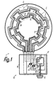
- Fig. 1
- eine erfindungsgemäße Heizeinheit in vereinfachter Ansicht und
- Fig. 2
- den Umschaltvorgang anhand einer Wechselstrom-Kennlinie.
- Fig. 1
- a heating unit according to the invention in a simplified view and
- Fig. 2
- the switching process based on an AC characteristic.
Die Heizeinheit 1 kann wenigstens teilweise als
Strahlheizkörper zur Anordnung an einer transluzenten
Herdplatte aus Glaskeramik o. dgl., als mit einer solchen
Kochstellen- bzw. Herdplatte baulich vereinte Heizeinheit,
als Elektrokochplatte mit einem metallischen Kochplattenkörper
o. dgl. ausgebildet sein und ist bevorzugt
als thermisch massearme Kochplatte in Dickschicht-Technik
ausgebildet, wobei die thermische Speicherkapazität
und/oder Leitungsfähigkeit ihres Werkstoffes
spezifisch zweckmäßig wesentlich geringer als diejenige
eines metallischen Werkstoffes, insbesondere von
Stahlguß ist. Zur Bildung heizender Bereiche sind nur
zwei Heizungen 3, 4 bzw. Heizwiderstände 5, 6 vorgesehen,
die jeweils einen von der anderen Heizung gesonderten,
in sich geschlossenen und gesondert steuer-
bzw. regelbaren Heizkreis bilden.The heating unit 1 can at least partially as
Radiant heaters for arrangement on a translucent
Stovetop made of glass ceramic or the like, as with such
Cooker or stove top structurally combined heating unit,
as an electric hotplate with a metallic hotplate body
or the like. and is preferred
as a low-mass hotplate using thick-film technology
formed, the thermal storage capacity
and / or conductivity of your material
specifically expediently much less than that
a metallic material, in particular of
Cast steel is. To form heating areas are only
two
Die Heizungen 3, 4 dienen zur Beheizung im Bereich
einer Heizfläche 2. Im Falle eines Strahlheizkörpers
kann vor dessen Montage an der Rückseite einer
Glaskeramikplatte die Heizfläche 2 als ein im wesentlichen
ebener Bereich verstanden werden, in dem die
Heizungen 3, 4 liegen bzw. bis zu dem die Heizwiderstände
5, 6 mit ihrer von einem thermisch und/oder elektrisch
isolierenden Träger abgekehrten Vorder- oder
Oberseite reichen. Die Heizwiderstände 5, 6 sind z. B.
an der Bodenoberseite dieses topfförmigen Isolationsträgers
angeordnet, der mit seinem Topfrand so an der
Rückseite der Kochplatte zu befestigen ist, daß die
Stirnseite seines Topfrandes im wesentlichen geschlossen
bzw. dicht mit Pressung an der Kochplatte anliegt
und die Heizungen 4, 5 innerhalb des Topfrandes liegen.The
Nach Verbindung des Strahlheizkörpers mit der
Kochplatte, im Falle der Anordnung mindestens eines
Heizwiderstandes an der Rückseite der Kochplatte als
aufkaschierter Dickschichtwiderstand und im Falle einer
Heizeinheit, bei welcher mindestens ein Heizwiderstand
in Form einer Widerstandswendel, eines Rohrheizkörpers
o. dgl. an der Rückseite der Kochplatte befestigt
bzw. elektrisch isoliert eingebettet ist, ist die Heizfläche
2 als die vom Heizwiderstand abgekehrte, im wesentlichen
ebene Seite der Kochplatte bzw. des Plattenkörpers
zur verstehen. In jedem Fall ist die Heizfläche 2 am
Außenumfang etwa in dem Bereich begrenzt, bis zu
welchem mindestens eine Heizung 3thermisch deutlich
und bereits kurze Zeit nach ihrem Einschalten erwärmend
wirkt, wobei der Radialabstand des Außenumfanges
bzw. der äußeren Begrenzung 9 der Heizfläche 2
vom äußersten Bereich der Heizungen 3, 4 wesentlich
kleiner als deren Radialerstreckung ist.After connecting the radiant heater with the
Hotplate, in the case of arrangement at least one
Heating resistor on the back of the hotplate as
laminated thick film resistance and in the case of a
Heating unit in which at least one heating resistor
in the form of a resistance coil, a tubular heater
or the like. Attached to the back of the hotplate
or embedded in an electrically insulated manner is the
Jeder Heizung 3, 4 ist eine gesonderte Temperaturfühlung
7, 8 zugeordnet, die zweckmäßig etwa im Bereich
der zugehörigen Heizung 3, 4 und/oder unmittelbar
benachbart zu derjenigen Seite dieser Heizung 3, 4
fühlt, die dem Zentrum der Heizfläche 2 zugekehrt ist.
Die Temperaturfühlung kann dabei im wesentlichen entlang
des gesamten zugehörigen Heizwiderstandes 6
bzw. 7 erfolgen. Ferner kann die Temperaturfühlung etwa
in der Ebene der zugehörigen Heizung 3 bzw. 4 oder,
z. B. im Fall eines Strahlheizkörpers, nahe bei oder an
der Rückseite der Kochplatte erfolgen, von welcher die
jeweilige Heizung 3 bzw. 4 freiliegend einen lichten Abstand
haben kann.Each
Zur manuellen sowie selbstätig in Abhängigkeit von
Bestimmungsgrößen erfolgenden Steuerung der Heizungen
3, 4 ist als Steuermittel eine Steuereinheit 10
vorgesehen, die zweckmäßig eine von der beheizten
Baugruppe gesonderte Baugruppe bildet und mit der
beheizten Baueinheit über flexible Verbindungsleitungen
verbunden ist. Die Steuereinheit 10 dient sowohl
zur manuellen Einstellung der gewünschten Temperatur
bzw. Heizleistung der beheizten Baugruppe als auch zur
selbstätigen Durchführung von Regelvorgängen aufgrund
von Temperaturwerten, die temperaturabhängig
veränderliche Meßwiderstände 11, 12 der Temperaturfühlungen
7, 8 über Signalleitungen an Steuer- bzw. Regelelemente
der Steuereinheit 10 weiterleiten.For manual and automatic depending on
Determination of the
Die Heizwiderstände 5, 6 sind annähernd geschlossen
ringförmig sowie koaxial ineinander angeordnet und
der jeweilige, streifenförmig langgestreckte Heizwiderstand
5 bzw. 6 hat innerhalb seines Ringverlaufes einen
mäanderartigen Verlauf dadurch, daß in Umfangsrichtung
aneinanderschließend verlaufende Umfangsabschnitte
unterschiedliche Radialabstände vom Zentrum
der Heizfläche 2 haben und über etwa radiale Zwischenabschnitte
ineinander übergehen, wobei die Umfangsabschnitte
nur zwei deutlich unterschiedliche Radialabstände
vom Zentrum haben, etwa gleich lang sind und
eine Länge haben, die wesentlich größer als ihre Breite
ist. Der jeweilige, gegenüber der Breite des Heizwiderstandes
wesentlich schmalere Meßwiderstand 11 bzw.
12 verläuft etwa parallel und mit geringem, annähernd
konstantem Abstand benachbart zur zugehörigen
Längskante des ihm zugeordneten Heizwiderstandes 5
bzw. 6, so daß auch der Meßwiderstand 11 bzw. 12 einen
mäanderartigen Verlauf hat und ringförmig annähernd
geschlossen ist. Der jeweilige Meßwiderstand 11
bzw. 12 kann ebenfalls als Dickschichtfühler, z. B. durch
Aufdrucken, unmittelbar auf die Rückseite der Kochplatte
aufkaschiert sein.The heating resistors 5, 6 are almost closed
arranged in a ring and coaxially one inside the other
the respective, strip-shaped elongated heating resistor
5 or 6 has one within its ring course
meandering course in that in the circumferential direction
contiguous circumferential sections
different radial distances from the center
have the
Durch die Heizwirkung der jeweiligen Heizung 3
bzw. 4 ist in der Heizfläche ein im wesentlichen ringförmig
geschlossener Flächenbereich 13 bzw. 14 bestimmt,
dessen radiale Ringbreite größer als die entsprechende
Streifenbreite des zugehörigen Heizwiderstandes
5 bzw. 6 und auch geringfügig größer als die
zugehörige Breite desjenigen Flächenfeldes ist, über
welches sich die Heizung 3 bzw. 4 in Folge ihres mäanderartigen
Verlaufes erstreckt, weil die Heizung 3 bzw.
4 geringfügig über dieses Flächenfeld hinaus durch
Strahlung und/oder Wärmeleitung deutlich meß- und
fühlbar wirkt. Der Außenumfang des äußeren Flächenbereiches
13 bestimmt die äußere Begrenzung 9 der
Heizfläche 2 und innerhalb des Innenumfanges des inneren
Flächenbereiches 14 ist keine Beheizung vorgesehen,
wobei die Weite dieses unbeheizten Innenfeldes
mindestens 1/3 so groß wie die Weite des Außenumfanges
9 ist. Zwischen den beiden miteinander berührungs-
bzw. übergangsfreien Heizungen 3, 4 schließen
die beiden Flächenbereich 13, 14 über eine zu ihnen
etwa parallel ringförmige Grenzzone 15 aneinander an,
die zwischen den genannten Flächenfeldem der
Heizwiderstände 5, 6 liegt und zweckmäßig keine linienoder
lückenförmige, sondern eine bandförmige Grenzzone
bildet, in welcher beide Heizungen 3, 4 bei Betrieb
gleichermaßen durch Strahlung und/oder Wärmeleitung
wirken können, wobei diese Grenzzone an beide
Flächenfelder im wesentlichen anschließen kann. Dadurch
ergibt sich zwischen dem Innenumfang und der
äußeren Begrenzung 9 eine im wesentlichen lückenlose
Beheizung der Heizfläche 2. Im Falle einer Kochplatte
definiert die äußere Begrenzung 9 die Größe der Boden-Aufstandsfläche
des auf dieser Kochplatte zu verwendenden
Kochgefäße. Statt einer kreisrunden Begrenzung
9 könnte auch eine rechteckige, langrunde
oder andere Begrenzung vorgesehen sein. Die äußere
Begrenzung 9 ist hinsichtlich der thermischen Beaufschlagung
lediglich dort geringfügig durchbrochen, wo
die Anschlußenden der Heizwiderstände 5, 6 quer zur
Mittelachse der Heizfläche 2 nach außen geführt sind.Due to the heating effect of the
Die Regel- und Steuereinheit 10 weist einen z. B.
gehäuseförmigen Sockel 16 aus elektrisch isolierendem
Werkstoff auf, in dem vorzugsweise vollständig
versenkt bzw. verkapselt alle elektrisch leitenden Teile
bis auf Anschlüsse für die Verbindungsleitungen zur beheizten
Baugruppe und Anschlüsse 17 für Stromversorgungs-
bzw. Geräteleitungen angeordnet sind. Der Sokkel
16 ist z. B. an der Innenseite einer Bedienungsblende
des zugehörigen Gerätes, wie eines Kochherdes zu
befestigen und weist eine über seine Außenseite frei zugänglich
vorstehende Handhabe 19 zur manuellen Einstellung
des jeweils gewünschten Betriebszustandes
auf. Die Handhabe 19 sitzt zweckmäßig auf einer Stellwelle
zur Betätigung von Kontakten, insbesondere von
Schaltkontakten 18, mit welchen Verbindungsleitungen
zwischen den Anschlüssen 17 und den übrigen elektrisch
leitenden Teilen allpolig geöffnet und geschlossen
werden können. Ausgehend von einer Nullstellung der
Handhabe 19, in welcher die Schaltkontakte 18 geöffnet
sind, dient ein erster Dreh-Schaltschritt zum Schließen
der Schaltkontakte 18 und weitere Drehschritte dienen
zur Einstellung der unterschiedlichen Betriebsweisen.The regulating and
Die Schaltwelle bzw. die Handhabe 19 wirkt hierzu
des weiteren auf eine elektronische Steuereinrichtung
20, die als gesonderte Baugruppe innerhalb des Sokkels
16 angeordnet ist. Die beiden, von den Anschlüssen
17 kommenden Verbindungsleitungen sind nach
den Schaltkontakten 18 an die zugehörigen
Anschlußenden der Heizwiderstände 5, 6 angeschlossen,
wobei eine Verbindungsleitung in gesonderte Anschlußleitungen
21, 22 für jeweils ein Anschlußende jedes
der Heizwiderstände 5, 6 verzweigt ist. In jeder
Anschlußleitung 21, 22 ist ein elektronisches Relais 23
bzw. 24 zwischengeschaltet, dessen Funktionszustände
von der Steuereinheit 10 jeweils über eine Steuerleitung
25 bzw. 26 gesteuert werden. Die Anschlußenden
der Meßwiderstände 11, 12 sind über Signalleitungen
27, 28 gesondert an Eingänge der Steuereinrichtung 20
angeschlossen, welche die von den Temperaturfühlungen
7, 8 gemessenen absoluten Temperaturen, deren
Unterschied sowie gegebenenfalls deren Zeitdauer verarbeitet
und abgeleitet davon Steuersignale an die Relais
23, 24 weitergibt. Die Steuerung ist so vorgesehen,
daß die Relais 23, 24 entweder beide für den Stromdurchgang
geschlossen sein können oder daß abwechselnd
das eine Relais geschlossen und das andere offen
ist, wobei beim Umschalten das Öffnen bzw. Schließen
des einen Relais zeitgleich mit dem Schließen bzw.
Öffnen des anderen Relais erfolgt.The control shaft or the
Die Steuereinheit 10 kann ein aufgrund einer Steuerbeheizung
taktend arbeitendes Leistungssteuergerät
und/oder ein Temperaturregler sein, der über einen oder
beide Temperaturfühler die Temperatur im Bereich der
Heizfläche 2 so überwacht, daß bei Erreichen einer eingestellten
Temperatur die den Heizungen 3, 4 zugeführte
elektrische Leistung heruntergeregelt und nach Unterschreiten
einer vorbestimmten unteren Grenztemperatur
wieder in vollem Umfang zugeführt wird. Gleichzeitig
arbeitet die Steuereinrichtung 20 nach Art einer
Vollwellensteuerung so, daß sie die Relais 23, 24 nur in
dem Augenblick umschaltet, in welchem die Kennlinie
des zugeführten Wechselstromes nach Beendigung einer
vollen Kennlinienwelle im Durchlauf durch die Null-Linie
ist, auf deren beiden Seiten die Wellenbögen der
Kennlinie liegen.The
In Fig. 2 ist die Kennlinie 29 einschließlich der Null-Linie
30 in zwei Ebenen dargestellt, und zwar in der oberen
Ebene während der Leistungsversorgung der äußeren
Heizung 3 und in der unteren Ebene während der
Leistungsversorgung der inneren Heizung 4 Die Relais
23, 24 werden z. B. so betrieben, daß aufeinanderfolgende
Wellenpakete von z. B. zwanzig aneinanderschließenden
Vollwellen der Kennlinie 29 jeweils in beliebiger
unterschiedlicher oder gleicher Verteilung unter
einmaliger Teilung zur Leistungsversorgung zeitlich aneinanderschließend
beiden Heizungen 3, 4 zugeführt
werden. Von den zwanzig Vollwellen jedes Wellenpaketes
kann dann z. B. ein Wellen-Teilpaket 33 mit acht kontinuierlich
aneinanderschließenden Vollwellen der Heizung
4 und dann durch Umschaltung 32 das verbleibende
Wellen-Teilpaket 34 mit zwölf Vollwellen der Heizung
3 zugeführt werden, wonach aufgrund einer weiteren
Umschaltung 32 das nächste Wellen-Teilpaket wieder
der Heizung 4 zugeführt wird usw. Das Verhältnis der
Anzahlen der Wellen zwischen den beiden Wellenteilpaketen
33, 34 kann dabei konstant bleiben oder, z. B.
temperaturabhängig, veränderbar sein. Die Umschaltung
32 erfolgt in jedem Fall beim Durchgang 31 der
Kennlinie 29 durch die Null-Linie 30.2 is the
Die beschriebene periodische Umschaltung kann
zwar in jedem Temperatur- bzw. eingestellten Leistungsbereich
der Heizeinheit, d.h. auch im niedrigeren
bzw. niedrigsten Leistungsbereich vorgesehen sein, besonders
zweckmäßig.ist sie jedoch in höheren bzw. im
höchsten Leistungsbereich, da dann eine schlechte
Wärmeentnahme in einem Flächenbereich 13 bzw. 14
schnell zur Überhitzung dieses Flächenbereiches führen
kann. In mindestens einem Leistungsbereich, z. B.
im niedrigeren oder niedrigsten Leistungsbereich kann
die Größe der beiden Wellen-Teilpakete 33, 34 etwa
gleichgroß sein, während erst im höheren bzw. höchsten
Leistungsbereich die genannte Differenzierung
dieses Größenverhältnisses erfolgt, um z. B. dem Umstand
Rechnung zu tragen, daß Kochgefäße in der Regel
im äußeren Flächenbereich 13 einen besseren Wärmeübergang
ermöglichen als im inneren Flächenbereich
14. Die Differenzierung des Größenverhältnisses
kann dabei mit zunehmender Temperatur im Bereich
der Heizfläche 2 auch kontinuierlich oder schrittweise
zunehmen.The periodic switching described can
in every temperature or set power range
the heating unit, i.e. even in the lower
or lowest power range can be provided, especially
it is appropriate, however, in higher or
highest performance range because then a bad one
Extraction of heat in a
Durch die periodische Umschaltung wird praktisch
aus einer einzigen Zuleitung über eine Weiche die elektrische
Energie laufend bzw. nur mit sehr kurzen Unterbrechungen
an mindestens zwei Heizungen 3, 4 desselben
Heizfeldes verteilt. Die Zeitintervalle der Zuteilung
bzw. Unterbrechung sind dabei im Verhältnis zur
thermischen Trägheit im Bereich der Heizfläche 2 so
kurz, daß die Temperatur des jeweiligen Flächenbereiches
während der Zuteilung nicht oder nur sehr unwesentlich
über die Temperatur während der Unterbrechung
der Zuteilung ansteigt, bzw. daß die Temperatur
während dieser Unterbrechung nicht oder nur sehr unwesentlich
unter die Temperatur während der Zuteilung
absinkt. Wegen der kurzen Zeitintervalle ergeben sich
im Bereich der Heizfläche 2 bzw. der Flächenbereiche
13, 14 konstante Temperaturen bzw. über zahlreiche
Umschalt-Perioden gleichgerichtet kontinuierliche Temperaturänderungen,
weil stets praktisch beide oder alle
Heizungen 3, 4 gleichzeitig in Betrieb bleiben und während
der Zuteilungspausen aufgrund ihrer thermischen
Trägheit in der beschriebenen Weise nicht wesentlich
unter ihre Betriebstemperatur abkühlen, sondern vor einer
solchen Abkühlung bereits wieder mit elektrischer
Energie versorgt werden.The periodic switchover makes it practical
the electrical from a single supply line via a switch
Energy running or only with very short interruptions
on at least two
Claims (10)
- An electric heating unit, particularly for a cooking point, comprising a heating area (2) and at least two electric heaters (3, 4) to be alternately switched to heating operation, each determining a rated operating capacity and provided for separate surface areas (13, 14) of the heating area (2) and controllable by control means (10) including temperature sensing means (7, 8), which are provided for periodical switching of at least a portion of a rated capacity between at least two of the heaters (3, 4), characterized in that for switching operation the control means (10) comprise means for the detection of the temperature ratio of the separate surface areas (13, 14), wherein the electrical power supplied to an electric heater (3) is reduced for a certain amount depending on the detected temperature ratio, wherein about this amount of electrical power is supplied to another heater (4) of the heating unit (1).
- An electric heating unit according to claim 1, characterized in that the heaters (3, 4) are mainly provided for the separate heating of the separate surface areas (13, 14), and the control means (10) are adapted for the separate temperature control of the separate surface areas (13, 14) by reciprocating capacity displacement of an in particular approximately constant electrical power supply between at least two heaters (3, 4), the stop intervals of the power supply being significantly shorter than a time lag with which, as a result of a thermal inertia in the vicinity of the particular heater (3, 4), a temperature drop occurs and preferably the time intervals between successive switching operations and/or the period duration between two switching operations in the same direction preferably being variable.
- An electric heating unit according to claim 1 or 2, characterized in that during the operation of the heaters (3, 4) with alternating current with a given characteristic (29) defining a zero line (30) associated with said alternating current characteristic, the switching on of a heater (3 or 4) occurs essentially at the same point of the characteristic (29) as the switching off of another heater (4, 3) that in particular there is provided a substantially continuous electronic switching and/or the power decrease in both switching states is approximately the same, that preferably at least two heaters (3, 4) in heating operation are constantly operated with the rated power, or are only controlled by the switching on and off as a function of transient times, the period duration particularly being significantly below one minute or at the most approximately one second, and preferably the switching over substantially occurs in the passage (31) of the characteristic (29) through the zero line (30) or the particular heater (3, 4) is supplied with power solely in the form of full wave groups from the characteristic (29).
- An electric heating unit according to any of the preceding claims, characterized in that the switching over is controlled as a function of temperature changes in the vicinity of at least one of the associated surface areas (13, 14) and in that particularly for at least two surface areas (13, 14) separate temperature sensors (7, 8) are provided, in that preferably the switching over is controlled in at least one, particularly lower, operating temperature range in a ' substantially time-dependent and/or in a temperature range above a limit temperature, particularly of approximately 250 °C, substantially in temperature-dependent manner, and in that preferably at least one of the time intervals for switching over of at least two heaters (3, 4) is manually adjustable and preferably at least two surface areas (13, 14) are operable in manually adjustable manner with different operating temperatures.
- An electric heating unit according to any of the preceding claims, characterized in that the control means (10) are provided as an overheating protection means and preferably on reaching a maximum temperature switch off at least one part of the rated power of at least one to all the heaters (3, 4) and/or that the control means (10) are constructed for pot detection, particularly as a function of the time duration of a temperature ratio between at least two surface areas (13, 14).
- An electric heating unit according to any of the preceding claims, characterized in that at least two heaters (3, 4), particularly in a precooking phase, are simultaneously operable and can preferably be changed in temperature- and/or time-dependent manner to separate temperature regulation and/or periodic switching over (32).
- An electric heating unit according to any of the preceding claims, characterized in that the temperature sensing (7, 8) is provided in the vicinity of an in particular thermally low-mass plate body and in that preferably at least two surface areas (13, 14) in each case have at least one separate temperature sensor (11, 12).
- An electric heating unit according to any of the preceding claims, characterized in that at least one heater (3, 4) is formed by at least one separate heating resistor (5, 6) located in a separate heating circuit and in that particularly all the heaters (3, 4) are in separate heating circuits and/or at least two heaters (3, 4) are juxtaposed and particularly in ring-like manner within one another and in that preferably said heaters (3, 4) overlap thermally associated surface areas (13, 14) in a boundary zone (15).
- An electric heating unit according to any of the preceding claims, characterized in that at least one heater (3, 4) and/or at least one temperature sensor (7, 8) is at least partly constructed as a thick-film resistor and preferably is arranged in strands of alternating directions or in a meandering course, and in that preferably at least two heaters (3, 4) and surface areas (13, 14) are associated with a common base surface for a single cooking vessel and wherein preferably at least one of these heaters (3, 4) is arranged thermally roughly axially symmetrically to said base surface.
- An electric heating unit according to any of the preceding claims, characterized in that the rated power of the particular heater (3, 4) is substantially the same as the total rated power of the heating unit (1) and preferably there are only two heaters (3, 4), which form two circular surface areas (13, 14) located within one another and having an unheated centre.
Applications Claiming Priority (2)
| Application Number | Priority Date | Filing Date | Title |
|---|---|---|---|
| DE4130337A DE4130337C2 (en) | 1991-09-12 | 1991-09-12 | Method for operating an electric heating unit and electric heating unit |
| DE4130337 | 1991-09-12 |
Publications (4)
| Publication Number | Publication Date |
|---|---|
| EP0531987A2 EP0531987A2 (en) | 1993-03-17 |
| EP0531987A3 EP0531987A3 (en) | 1994-05-04 |
| EP0531987B1 EP0531987B1 (en) | 1998-10-21 |
| EP0531987B2 true EP0531987B2 (en) | 2003-11-05 |
Family
ID=6440439
Family Applications (1)
| Application Number | Title | Priority Date | Filing Date |
|---|---|---|---|
| EP92115467A Expired - Lifetime EP0531987B2 (en) | 1991-09-12 | 1992-09-10 | Electrical heating unit |
Country Status (6)
| Country | Link |
|---|---|
| US (1) | US5396047A (en) |
| EP (1) | EP0531987B2 (en) |
| JP (1) | JP3257639B2 (en) |
| AT (1) | ATE172554T1 (en) |
| DE (2) | DE4130337C2 (en) |
| ES (1) | ES2125877T3 (en) |
Families Citing this family (52)
| Publication number | Priority date | Publication date | Assignee | Title |
|---|---|---|---|---|
| US6011242A (en) * | 1993-11-01 | 2000-01-04 | Quadlux, Inc. | Method and apparatus of cooking food in a lightwave oven |
| US5534678A (en) * | 1993-11-12 | 1996-07-09 | General Electric Company | Oven with improved self-cleaning cycle |
| CA2180618A1 (en) * | 1995-07-17 | 1997-01-18 | Dennis J. Vaseloff | Food warmer foil heater and sensor assembly including plural zone heater assembly |
| DE19604658A1 (en) * | 1996-02-09 | 1997-08-14 | Ako Werke Gmbh & Co | Temperature measuring device for a control circuit of an electric radiant heater |
| EP0853444B1 (en) * | 1997-01-10 | 2005-11-23 | E.G.O. ELEKTRO-GERÄTEBAU GmbH | Cooking system with an electric cooking-plate, transferring heat by conduction |
| GB2327541A (en) * | 1997-07-17 | 1999-01-27 | Ceramaspeed Ltd | Electric heater control for a glass-ceramic top cooking appliance |
| DE29714770U1 (en) * | 1997-08-18 | 1997-11-27 | Rieker Elektronik | Heating device for an electrical device and electrical device for heating a liquid |
| DE19738677A1 (en) * | 1997-09-04 | 1999-03-11 | Ego Elektro Geraetebau Gmbh | Power control device |
| US5990454A (en) | 1997-09-23 | 1999-11-23 | Quadlux, Inc. | Lightwave oven and method of cooking therewith having multiple cook modes and sequential lamp operation |
| US6013900A (en) | 1997-09-23 | 2000-01-11 | Quadlux, Inc. | High efficiency lightwave oven |
| US5958271A (en) | 1997-09-23 | 1999-09-28 | Quadlux, Inc. | Lightwave oven and method of cooking therewith with cookware reflectivity compensation |
| DE19748134A1 (en) * | 1997-10-31 | 1999-05-12 | Rowenta Werke Gmbh | Distributing limited electric power in irons |
| EP1027637B1 (en) * | 1997-11-07 | 2002-09-11 | Shell Oil Company | Heater control |
| FR2773873B1 (en) * | 1998-01-20 | 2000-02-25 | Eurokera | COOKING APPLIANCE |
| DE19861478B4 (en) * | 1998-01-20 | 2013-03-28 | Electrolux Rothenburg Gmbh Factory And Development | Electric cooker hob heating element with multiple heating areas |
| WO2000006822A1 (en) * | 1998-07-29 | 2000-02-10 | Marcello Ferrante | Process for the controlled power supply of machines for steam generation and appliances connected thereto |
| US6469283B1 (en) * | 1999-03-04 | 2002-10-22 | Applied Materials, Inc. | Method and apparatus for reducing thermal gradients within a substrate support |
| JP3293594B2 (en) * | 1999-06-29 | 2002-06-17 | 住友電気工業株式会社 | Apparatus and method for heating protective member of optical fiber fusion spliced part |
| US6100506A (en) * | 1999-07-26 | 2000-08-08 | International Business Machines Corporation | Hot plate with in situ surface temperature adjustment |
| DE19948313A1 (en) * | 1999-10-07 | 2001-04-12 | Alcatel Sa | Electric heating and method for regulating an electric heating |
| GB2361160B (en) * | 2000-04-03 | 2004-11-03 | Ceramaspeed Ltd | Radiant electric heater |
| DE10053415A1 (en) * | 2000-10-27 | 2002-05-29 | Bsh Bosch Siemens Hausgeraete | Electric radiator |
| DE10111734A1 (en) * | 2001-03-06 | 2002-09-26 | Schott Glas | Ceramic cooking system with glass ceramic plate, insulation layer and heating elements |
| DE10131995B4 (en) * | 2001-03-07 | 2008-07-03 | Eichenauer Heizelemente Gmbh & Co. Kg | Heating insert for an electrically heated cooking vessel |
| DE10147074A1 (en) | 2001-09-25 | 2003-05-08 | Beru Ag | Method for operating a multi-stage electric heater consisting of several heating elements |
| GB0203826D0 (en) * | 2002-02-19 | 2002-04-03 | Ceramaspeed Ltd | Electric heater assembly |
| CN100443009C (en) * | 2002-08-01 | 2008-12-17 | 陈永坚 | Improved personal care device with thermal feedback and operation conditions display |
| US20040222210A1 (en) * | 2003-05-08 | 2004-11-11 | Hongy Lin | Multi-zone ceramic heating system and method of manufacture thereof |
| CN100539765C (en) * | 2003-07-30 | 2009-09-09 | 皇家飞利浦电子股份有限公司 | Domestic appliance and the heating arrangement that is used for domestic appliance |
| FR2859867B1 (en) * | 2003-09-16 | 2006-04-14 | Frima Sa | HEATING ELEMENT FOR COOKING APPARATUS |
| EP1946615A4 (en) * | 2005-10-05 | 2015-04-01 | Evo Inc | Electric cooking apparatus |
| US20070114221A1 (en) * | 2005-11-24 | 2007-05-24 | Samsung Electronics Co., Ltd. | Plate-shaped heater and steam cooking apparatus including the same |
| US20080076077A1 (en) * | 2006-09-21 | 2008-03-27 | Toshiba America Electronic Components, Inc. | Apparatus and method for heating semiconductor wafers with improved temperature uniformity |
| US20080142505A1 (en) * | 2006-12-18 | 2008-06-19 | Bsh Home Appliances Corporation | Low simmer heating element with mechanical switches |
| DE102007008895A1 (en) * | 2007-02-23 | 2008-08-28 | BSH Bosch und Siemens Hausgeräte GmbH | burner plate |
| DE102007026704A1 (en) * | 2007-06-06 | 2008-12-18 | Miele & Cie. Kg | Method for controlling a hob and apparatus for carrying out the method |
| US9320293B2 (en) * | 2008-06-06 | 2016-04-26 | Gold Medal Products Company | Popcorn kettle |
| DE102008041184B4 (en) * | 2008-08-12 | 2023-08-17 | BSH Hausgeräte GmbH | Method and device for operating a hotplate of a hob |
| GB2481217B (en) * | 2010-06-15 | 2017-06-07 | Otter Controls Ltd | Thick film heaters |
| US9538583B2 (en) * | 2013-01-16 | 2017-01-03 | Applied Materials, Inc. | Substrate support with switchable multizone heater |
| EP2975386B1 (en) * | 2014-07-14 | 2020-09-02 | Sensirion AG | Heater structure for a sensor device |
| DK3411629T3 (en) * | 2016-02-01 | 2022-03-21 | Evo Inc | COOKING SYSTEM WITH SEVERAL HEATING ELEMENTS |
| WO2017138159A1 (en) * | 2016-02-08 | 2017-08-17 | 株式会社サンテックコーポレーション | Method for double-sided heat cooking of foodstuff to be heated and electrothermic cooking appliance employed in same |
| US10136664B2 (en) | 2016-07-11 | 2018-11-27 | Gold Medal Products Company | Popcorn popping machines and methods for different types of popcorn kernels and different popped popcorn types |
| US10852271B2 (en) * | 2016-12-14 | 2020-12-01 | Taiwan Semiconductor Manufacturing Co., Ltd. | On-chip heater |
| US11067288B2 (en) | 2017-05-15 | 2021-07-20 | Backer Ehp Inc. | Dual coil electric heating element |
| US10132504B1 (en) | 2017-05-15 | 2018-11-20 | Backer Ehp Inc. | Dual coil electric heating element |
| KR102110417B1 (en) * | 2018-08-21 | 2020-05-13 | 엘지전자 주식회사 | Electric Heater |
| KR102091251B1 (en) * | 2018-08-21 | 2020-03-19 | 엘지전자 주식회사 | Electric Heater |
| USD955168S1 (en) | 2019-07-03 | 2022-06-21 | Backer Ehp Inc. | Electric heating element |
| US11581156B2 (en) | 2019-07-03 | 2023-02-14 | Backer Ehp Inc. | Dual coil electric heating element |
| WO2021206994A1 (en) * | 2020-04-07 | 2021-10-14 | Sharkninja Operating Llc | Cooking system temperature management |
Citations (11)
| Publication number | Priority date | Publication date | Assignee | Title |
|---|---|---|---|---|
| DE2705528A1 (en) † | 1977-02-10 | 1978-08-24 | Weiss Kg Alfons | Electric cooker heating elements control circuit - has counter supplied with clock pulses and with output gated to switch |
| DE2749765A1 (en) † | 1977-11-07 | 1979-05-10 | Baumgartner | Low radio interference control circuit - has switches which are triacs controlled by pulses synchronised with load current zero crossings |
| US4394564A (en) † | 1981-12-21 | 1983-07-19 | General Electric Company | Solid plate heating unit |
| DE2932844C2 (en) † | 1979-08-14 | 1984-02-16 | Gebrüder Thielmann AG KG, 6342 Haiger | Built-in hob |
| DE3314501A1 (en) † | 1983-04-21 | 1984-10-25 | Ego Elektro Blanc & Fischer | Heating element, especially a radiant heating element for heating glass-ceramic plates |
| DE3334425A1 (en) † | 1983-09-23 | 1985-04-11 | Licentia Patent-Verwaltungs-Gmbh, 6000 Frankfurt | Additional switching device for a hotplate or cooking point which is integrated into a cooking hob or the like and has at least two heating resistors as the load |
| DE3539581A1 (en) † | 1985-11-08 | 1987-05-21 | Philips Patentverwaltung | METHOD FOR CONTROLLING SEVERAL ELECTRICAL LOADS |
| DE3545454A1 (en) † | 1985-12-20 | 1987-07-02 | Bosch Siemens Hausgeraete | Heating element for thermal domestic appliances, especially for hotplates |
| DE3903978A1 (en) † | 1989-02-10 | 1990-08-16 | Imp Werke Gmbh | Infrared hob having at least two infrared tubes |
| DE4007680A1 (en) † | 1990-03-10 | 1991-09-19 | Grass Ag | Glass-ceramic cooking hob - has field of sensor-driven elements each a preset different power outputs |
| EP0471171A2 (en) † | 1990-07-18 | 1992-02-19 | Schott Glaswerke | Device for regulating and limiting the power of a heating plate of ceramic or similar material |
Family Cites Families (16)
| Publication number | Priority date | Publication date | Assignee | Title |
|---|---|---|---|---|
| JPS5115835A (en) * | 1974-07-31 | 1976-02-07 | Kokusai Electric Co Ltd | |
| US4282422A (en) * | 1979-02-01 | 1981-08-04 | General Electric Company | Power control for appliance using multiple high inrush current elements |
| GB2064239A (en) * | 1979-11-23 | 1981-06-10 | Thorn Domestic Appliances Ltd | Power supply for electric cooker |
| GB2067880B (en) * | 1980-01-14 | 1985-01-03 | Johnson Matthey Co Ltd | Glass ceramic hob including temperature sensor |
| GB2067857A (en) * | 1980-01-15 | 1981-07-30 | Thorn Domestic Appliances Ltd | Power control apparatus |
| SU961161A1 (en) * | 1981-02-11 | 1982-09-23 | Белорусский институт механизации сельского хозяйства | Apparatus for controlling installation for electrode heating of conductive medium |
| US4441015A (en) * | 1982-01-04 | 1984-04-03 | General Electric Company | Cooking apparatus employing a rotisserie mode with stationary food |
| DE8515560U1 (en) * | 1985-05-25 | 1985-08-29 | E.G.O. Elektro-Geräte Blanc u. Fischer, 7519 Oberderdingen | Hotplate heating |
| EP0234373A3 (en) * | 1986-02-26 | 1988-03-02 | E.G.O. Elektro-Geräte Blanc u. Fischer | Cooking unit with radiant heating element |
| US4740664A (en) * | 1987-01-05 | 1988-04-26 | General Electric Company | Temperature limiting arrangement for a glass-ceramic cooktop appliance |
| US4836138A (en) * | 1987-06-18 | 1989-06-06 | Epsilon Technology, Inc. | Heating system for reaction chamber of chemical vapor deposition equipment |
| US4786799A (en) * | 1987-07-27 | 1988-11-22 | General Electric Company | Power control for cooking appliance with multiple heating units |
| DE3810586A1 (en) * | 1988-03-29 | 1989-10-12 | Ego Elektro Blanc & Fischer | Heating system for electric cooking appliances |
| GB8924936D0 (en) * | 1989-11-04 | 1989-12-28 | Ceramaspeed Ltd | Radiant electric heaters |
| DE4022844C1 (en) * | 1990-07-18 | 1992-02-27 | Schott Glaswerke, 6500 Mainz, De | |
| GB2263379B (en) * | 1992-01-10 | 1995-07-26 | Ceramaspeed Ltd | Radiant heater having multiple heating zones |
-
1991
- 1991-09-12 DE DE4130337A patent/DE4130337C2/en not_active Expired - Fee Related
-
1992
- 1992-09-10 AT AT92115467T patent/ATE172554T1/en not_active IP Right Cessation
- 1992-09-10 DE DE59209535T patent/DE59209535D1/en not_active Expired - Fee Related
- 1992-09-10 ES ES92115467T patent/ES2125877T3/en not_active Expired - Lifetime
- 1992-09-10 EP EP92115467A patent/EP0531987B2/en not_active Expired - Lifetime
- 1992-09-11 JP JP26778292A patent/JP3257639B2/en not_active Expired - Fee Related
- 1992-09-14 US US07/944,445 patent/US5396047A/en not_active Expired - Fee Related
Patent Citations (11)
| Publication number | Priority date | Publication date | Assignee | Title |
|---|---|---|---|---|
| DE2705528A1 (en) † | 1977-02-10 | 1978-08-24 | Weiss Kg Alfons | Electric cooker heating elements control circuit - has counter supplied with clock pulses and with output gated to switch |
| DE2749765A1 (en) † | 1977-11-07 | 1979-05-10 | Baumgartner | Low radio interference control circuit - has switches which are triacs controlled by pulses synchronised with load current zero crossings |
| DE2932844C2 (en) † | 1979-08-14 | 1984-02-16 | Gebrüder Thielmann AG KG, 6342 Haiger | Built-in hob |
| US4394564A (en) † | 1981-12-21 | 1983-07-19 | General Electric Company | Solid plate heating unit |
| DE3314501A1 (en) † | 1983-04-21 | 1984-10-25 | Ego Elektro Blanc & Fischer | Heating element, especially a radiant heating element for heating glass-ceramic plates |
| DE3334425A1 (en) † | 1983-09-23 | 1985-04-11 | Licentia Patent-Verwaltungs-Gmbh, 6000 Frankfurt | Additional switching device for a hotplate or cooking point which is integrated into a cooking hob or the like and has at least two heating resistors as the load |
| DE3539581A1 (en) † | 1985-11-08 | 1987-05-21 | Philips Patentverwaltung | METHOD FOR CONTROLLING SEVERAL ELECTRICAL LOADS |
| DE3545454A1 (en) † | 1985-12-20 | 1987-07-02 | Bosch Siemens Hausgeraete | Heating element for thermal domestic appliances, especially for hotplates |
| DE3903978A1 (en) † | 1989-02-10 | 1990-08-16 | Imp Werke Gmbh | Infrared hob having at least two infrared tubes |
| DE4007680A1 (en) † | 1990-03-10 | 1991-09-19 | Grass Ag | Glass-ceramic cooking hob - has field of sensor-driven elements each a preset different power outputs |
| EP0471171A2 (en) † | 1990-07-18 | 1992-02-19 | Schott Glaswerke | Device for regulating and limiting the power of a heating plate of ceramic or similar material |
Also Published As
| Publication number | Publication date |
|---|---|
| ATE172554T1 (en) | 1998-11-15 |
| DE4130337A1 (en) | 1993-03-18 |
| DE4130337C2 (en) | 2002-05-02 |
| EP0531987A2 (en) | 1993-03-17 |
| ES2125877T3 (en) | 1999-03-16 |
| DE59209535D1 (en) | 1998-11-26 |
| EP0531987A3 (en) | 1994-05-04 |
| EP0531987B1 (en) | 1998-10-21 |
| US5396047A (en) | 1995-03-07 |
| JP3257639B2 (en) | 2002-02-18 |
| JPH06201140A (en) | 1994-07-19 |
Similar Documents
| Publication | Publication Date | Title |
|---|---|---|
| EP0531987B2 (en) | Electrical heating unit | |
| DE4022846C2 (en) | Device for power control and limitation in a heating surface made of glass ceramic or a comparable material | |
| EP0103741B1 (en) | Heating element, especially radiant heating element for the heating of ceramic plates | |
| EP0250880B1 (en) | Radiant heating element | |
| EP0234373A2 (en) | Cooking unit with radiant heating element | |
| EP0652688B1 (en) | Method of controlling the heating power of a vitroceramic hob according to required cooking conditions | |
| DE19813550A1 (en) | Method for operating an electric heating device | |
| DE2310867C3 (en) | Control device for electric hotplates | |
| DE2627373B2 (en) | Signal device on cooking appliances with a glass ceramic hob | |
| DE10111734A1 (en) | Ceramic cooking system with glass ceramic plate, insulation layer and heating elements | |
| EP1448024A2 (en) | Heating device with two areas | |
| DE1615231C3 (en) | Power control of electrical heating devices | |
| DE3314501A1 (en) | Heating element, especially a radiant heating element for heating glass-ceramic plates | |
| EP3764738B1 (en) | Food preparation device with ptc resistors in parallel | |
| EP0371295B1 (en) | Radiant heating element | |
| EP0079483B1 (en) | Control device for an electrical cooking plate | |
| EP0467111A2 (en) | Electrical radiant heating element | |
| DE2459649A1 (en) | Boiling plate with three heating resistors - is controlled by seven position switch and temperature limiter on boiling plate | |
| DE19820108C2 (en) | Arrangement of a heat-conducting ceramic carrier with a heating element as a cooking zone in a recess in a cooking surface | |
| EP0288916A2 (en) | Heater for a cooking oven | |
| DE60220784T2 (en) | METHOD AND DEVICE FOR REGULATING A COOKING DEVICE | |
| DE3108640A1 (en) | Signalling device for indicating the temperature state of cooking appliances | |
| EP2983449B1 (en) | Method for accelerating a cooking process, control device and cooking device for same | |
| EP2087821B1 (en) | Grill device | |
| DE3144631A1 (en) | Electrical hotplate |
Legal Events
| Date | Code | Title | Description |
|---|---|---|---|
| PUAI | Public reference made under article 153(3) epc to a published international application that has entered the european phase |
Free format text: ORIGINAL CODE: 0009012 |
|
| AK | Designated contracting states |
Kind code of ref document: A2 Designated state(s): AT CH DE ES FR GB IT LI SE |
|
| PUAL | Search report despatched |
Free format text: ORIGINAL CODE: 0009013 |
|
| AK | Designated contracting states |
Kind code of ref document: A3 Designated state(s): AT CH DE ES FR GB IT LI SE |
|
| 17P | Request for examination filed |
Effective date: 19940709 |
|
| RAP1 | Party data changed (applicant data changed or rights of an application transferred) |
Owner name: E.G.O. ELEKTRO-GERAETE BLANC UND FISCHER GMBH & CO |
|
| 17Q | First examination report despatched |
Effective date: 19950818 |
|
| RAP1 | Party data changed (applicant data changed or rights of an application transferred) |
Owner name: E.G.O. ELEKTRO-GERAETEBAU GMBH |
|
| GRAG | Despatch of communication of intention to grant |
Free format text: ORIGINAL CODE: EPIDOS AGRA |
|
| GRAG | Despatch of communication of intention to grant |
Free format text: ORIGINAL CODE: EPIDOS AGRA |
|
| GRAH | Despatch of communication of intention to grant a patent |
Free format text: ORIGINAL CODE: EPIDOS IGRA |
|
| GRAH | Despatch of communication of intention to grant a patent |
Free format text: ORIGINAL CODE: EPIDOS IGRA |
|
| GRAA | (expected) grant |
Free format text: ORIGINAL CODE: 0009210 |
|
| AK | Designated contracting states |
Kind code of ref document: B1 Designated state(s): AT CH DE ES FR GB IT LI SE |
|
| PG25 | Lapsed in a contracting state [announced via postgrant information from national office to epo] |
Ref country code: GB Free format text: LAPSE BECAUSE OF FAILURE TO SUBMIT A TRANSLATION OF THE DESCRIPTION OR TO PAY THE FEE WITHIN THE PRESCRIBED TIME-LIMIT Effective date: 19981021 Ref country code: FR Free format text: LAPSE BECAUSE OF NON-PAYMENT OF DUE FEES Effective date: 19981021 |
|
| REF | Corresponds to: |
Ref document number: 172554 Country of ref document: AT Date of ref document: 19981115 Kind code of ref document: T |
|
| REG | Reference to a national code |
Ref country code: CH Ref legal event code: EP |
|
| REF | Corresponds to: |
Ref document number: 59209535 Country of ref document: DE Date of ref document: 19981126 |
|
| ITF | It: translation for a ep patent filed |
Owner name: ORGANIZZAZIONE D'AGOSTINI |
|
| ET | Fr: translation filed | ||
| REG | Reference to a national code |
Ref country code: ES Ref legal event code: FG2A Ref document number: 2125877 Country of ref document: ES Kind code of ref document: T3 |
|
| GBV | Gb: ep patent (uk) treated as always having been void in accordance with gb section 77(7)/1977 [no translation filed] |
Effective date: 19981021 |
|
| PLBQ | Unpublished change to opponent data |
Free format text: ORIGINAL CODE: EPIDOS OPPO |
|
| PLBI | Opposition filed |
Free format text: ORIGINAL CODE: 0009260 |
|
| PLBF | Reply of patent proprietor to notice(s) of opposition |
Free format text: ORIGINAL CODE: EPIDOS OBSO |
|
| 26 | Opposition filed |
Opponent name: SCHOTT GLAS Effective date: 19990720 |
|
| PG25 | Lapsed in a contracting state [announced via postgrant information from national office to epo] |
Ref country code: AT Free format text: LAPSE BECAUSE OF NON-PAYMENT OF DUE FEES Effective date: 19990910 |
|
| PGFP | Annual fee paid to national office [announced via postgrant information from national office to epo] |
Ref country code: FR Payment date: 19990917 Year of fee payment: 8 Ref country code: ES Payment date: 19990917 Year of fee payment: 8 |
|
| PGFP | Annual fee paid to national office [announced via postgrant information from national office to epo] |
Ref country code: SE Payment date: 19990921 Year of fee payment: 8 |
|
| PLBF | Reply of patent proprietor to notice(s) of opposition |
Free format text: ORIGINAL CODE: EPIDOS OBSO |
|
| PG25 | Lapsed in a contracting state [announced via postgrant information from national office to epo] |
Ref country code: LI Free format text: LAPSE BECAUSE OF NON-PAYMENT OF DUE FEES Effective date: 19990930 Ref country code: CH Free format text: LAPSE BECAUSE OF NON-PAYMENT OF DUE FEES Effective date: 19990930 |
|
| PLBF | Reply of patent proprietor to notice(s) of opposition |
Free format text: ORIGINAL CODE: EPIDOS OBSO |
|
| PLBF | Reply of patent proprietor to notice(s) of opposition |
Free format text: ORIGINAL CODE: EPIDOS OBSO |
|
| REG | Reference to a national code |
Ref country code: CH Ref legal event code: PL |
|
| PG25 | Lapsed in a contracting state [announced via postgrant information from national office to epo] |
Ref country code: ES Free format text: LAPSE BECAUSE OF NON-PAYMENT OF DUE FEES Effective date: 20000911 |
|
| PG25 | Lapsed in a contracting state [announced via postgrant information from national office to epo] |
Ref country code: SE Free format text: THE PATENT HAS BEEN ANNULLED BY A DECISION OF A NATIONAL AUTHORITY Effective date: 20000929 |
|
| EUG | Se: european patent has lapsed |
Ref document number: 92115467.0 |
|
| REG | Reference to a national code |
Ref country code: FR Ref legal event code: ST |
|
| PLAW | Interlocutory decision in opposition |
Free format text: ORIGINAL CODE: EPIDOS IDOP |
|
| PLAW | Interlocutory decision in opposition |
Free format text: ORIGINAL CODE: EPIDOS IDOP |
|
| PUAH | Patent maintained in amended form |
Free format text: ORIGINAL CODE: 0009272 |
|
| STAA | Information on the status of an ep patent application or granted ep patent |
Free format text: STATUS: PATENT MAINTAINED AS AMENDED |
|
| 27A | Patent maintained in amended form |
Effective date: 20031105 |
|
| AK | Designated contracting states |
Kind code of ref document: B2 Designated state(s): AT CH DE ES FR GB IT LI SE |
|
| REG | Reference to a national code |
Ref country code: ES Ref legal event code: FD2A Effective date: 20011011 |
|
| EN | Fr: translation not filed | ||
| PG25 | Lapsed in a contracting state [announced via postgrant information from national office to epo] |
Ref country code: IT Free format text: LAPSE BECAUSE OF NON-PAYMENT OF DUE FEES;WARNING: LAPSES OF ITALIAN PATENTS WITH EFFECTIVE DATE BEFORE 2007 MAY HAVE OCCURRED AT ANY TIME BEFORE 2007. THE CORRECT EFFECTIVE DATE MAY BE DIFFERENT FROM THE ONE RECORDED. Effective date: 20050910 |
|
| PGFP | Annual fee paid to national office [announced via postgrant information from national office to epo] |
Ref country code: DE Payment date: 20051031 Year of fee payment: 14 |
|
| PG25 | Lapsed in a contracting state [announced via postgrant information from national office to epo] |
Ref country code: DE Free format text: LAPSE BECAUSE OF NON-PAYMENT OF DUE FEES Effective date: 20070403 |