EP0529558B1 - Entfernungsmesser für Abstand zwischen Fahrzeugen - Google Patents
Entfernungsmesser für Abstand zwischen Fahrzeugen Download PDFInfo
- Publication number
- EP0529558B1 EP0529558B1 EP19920114393 EP92114393A EP0529558B1 EP 0529558 B1 EP0529558 B1 EP 0529558B1 EP 19920114393 EP19920114393 EP 19920114393 EP 92114393 A EP92114393 A EP 92114393A EP 0529558 B1 EP0529558 B1 EP 0529558B1
- Authority
- EP
- European Patent Office
- Prior art keywords
- image
- car
- window
- tracking
- tracking window
- Prior art date
- Legal status (The legal status is an assumption and is not a legal conclusion. Google has not performed a legal analysis and makes no representation as to the accuracy of the status listed.)
- Expired - Lifetime
Links
Images

Classifications
-
- G—PHYSICS
- G01—MEASURING; TESTING
- G01S—RADIO DIRECTION-FINDING; RADIO NAVIGATION; DETERMINING DISTANCE OR VELOCITY BY USE OF RADIO WAVES; LOCATING OR PRESENCE-DETECTING BY USE OF THE REFLECTION OR RERADIATION OF RADIO WAVES; ANALOGOUS ARRANGEMENTS USING OTHER WAVES
- G01S3/00—Direction-finders for determining the direction from which infrasonic, sonic, ultrasonic, or electromagnetic waves, or particle emission, not having a directional significance, are being received
- G01S3/78—Direction-finders for determining the direction from which infrasonic, sonic, ultrasonic, or electromagnetic waves, or particle emission, not having a directional significance, are being received using electromagnetic waves other than radio waves
- G01S3/782—Systems for determining direction or deviation from predetermined direction
- G01S3/785—Systems for determining direction or deviation from predetermined direction using adjustment of orientation of directivity characteristics of a detector or detector system to give a desired condition of signal derived from that detector or detector system
- G01S3/786—Systems for determining direction or deviation from predetermined direction using adjustment of orientation of directivity characteristics of a detector or detector system to give a desired condition of signal derived from that detector or detector system the desired condition being maintained automatically
- G01S3/7864—T.V. type tracking systems
- G01S3/7865—T.V. type tracking systems using correlation of the live video image with a stored image
-
- G—PHYSICS
- G01—MEASURING; TESTING
- G01S—RADIO DIRECTION-FINDING; RADIO NAVIGATION; DETERMINING DISTANCE OR VELOCITY BY USE OF RADIO WAVES; LOCATING OR PRESENCE-DETECTING BY USE OF THE REFLECTION OR RERADIATION OF RADIO WAVES; ANALOGOUS ARRANGEMENTS USING OTHER WAVES
- G01S11/00—Systems for determining distance or velocity not using reflection or reradiation
- G01S11/12—Systems for determining distance or velocity not using reflection or reradiation using electromagnetic waves other than radio waves
Definitions
- FR-A-2 611 053 discloses an inter-car distance detecting device including two cameras, a monitoring video means and a means for setting a small square in a display area. On the basis of a stereoscopic technique, the distance to a predetermined point is calculated. A coordinator checks a cross in said square by forming comparator windows and on the basis of the mutual correlation therebetween, the coordinator selects one of the new comparator windows, into which the reference cross has been moved. The correlation technique is based on a Taylor series expansion.
- US-A-4 931 937 describes a distance detector mounted on a vehicle, where the concentration degree of features of a preceding vehicle, such as the edges extract from the image of the vehicle, is searched on the basis of such features in order to define a region, where a vehicle image is subjected to distance detecting.
- This distance detector does not relate to the tracking of a vehicle running ahead. What is done here is the vertical and horizontal differentiation to detect the contours of an obstacle such as the preceding car.
- the individual line segments are "labeled". When the labeling with respect to the vertical or horizontal differentiation is completed, then the line segment furthest downward becomes the center in the Y-direction of the window screen. Thus, the bottom line will be placed in the center of the window, rather than the image itself.
- Optical distance detecting devices have been further disclosed, for instance, in Japanese Patent Application Publication No's 38085/1988 and 46363/1988.
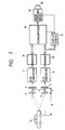
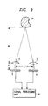
- Each of those conventional optical distance detecting devices as shown in FIG. 8, has two optical systems respectively on the right and left sides.
- the two optical systems are made up of lenses 1 and 2 which are spaced from each other as much as a base length L.
- Two image sensors 3 and 4 are provided at the focal points of the lenses 1 and 2, respectively, to output image signals, which are applied to a signal processing unit 30.
- the signal processing unit 30 electrically superimposes the image signals on each other while shifting them successively.
- Japanese Patent Application Publication No. 33352/1985 discloses a method of tracking the image of a car running ahead, which has been detected by an image sensor or the like.
- the operator sets a tracking gate (or window), which surrounds an object to be tracked, in the display screen while watching it, so that the image of the object is tracked on the display screen.
- the device may be installed on a motor car, to measure the distance between the motor car (hereinafter referred to as "a first car”) and another motor car running ahead of the first car (hereinafter referred to as "a second car”).
- a first car the motor car
- a second car another motor car running ahead of the first car
- a third car a further motor car different from the second car is running on the right or left side of the second car
- a conventional image tracking device is so designed that an operator sets a gate (or window), which surrounds a target to be tracked, in the display screen while watching it, thereby to track the image of the target.
- the device is installed on his motor car to track the image of a motor car running ahead of his motor car during traveling, he, while driving his car, has to watch the display screen to set the window in such a manner that it surrounds the image of the motor car running ahead.
- the position of the window thus manually set may be shifted from the image of the aimed motor car.
- the advantage of the inter-car distance detecting device is that even when a target selected is moved, the distance to the target can be continuously measured as long as it is in the field of sight, and that even in the case where there are a plurality of motor cars running ahead, it can be detected which of the cars is under distance measurement, and the operator can accurately, efficiently and safely set the window for tracking the image of a motor car running ahead while driving his motor car, so that the image of the car can be tracked with high stability.
- the inter-car distance detecting device of the invention calculates the distance between the first and second cars by detecting the amount of shift between the upper and lower image signals with the image signal in the window as a reference signal, and operates to monitor and correct the position of the tracking window according to the image signal data in the tracking window from the time when the tracking window is set by an operator.
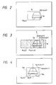
- reference numerals 1 and 2 designate lenses forming the upper and lower optical systems; 3 and 4, two-dimensional image sensors provided for the lenses 1 and 2, respectively; 5, a motor car to be tracked (hereinafter referred to as “a second car") which is running ahead of a motor car on which an inter-car distance detecting device is installed (hereinafter referred to as "a first car”); 6 and 7, analog-to-digital converters; 8 and 9, memories; 10, a microcomputer; and 11, a display screen for displaying an image detected by the lower image sensor, the display screen 11 being controlled by the microcomputer 10.
- reference numeral 12 designates an image tracking device.
- the image tracking device 12 forms a window 14 for tracking the image 5a of the second car 5 in the display screen 11 as shown in FIG. 3, and tracks the image 5a surrounded by the window 14.
- the image tracking function of the device 12 includes a function of changing the position of the window 14 so that the right and left parts of the image in the window are symmetrical.
- Reference numeral 13 designates an image tracking instruction switch which is operated by an operator.
- the tracking instruction switch 13 When, under this condition, the tracking instruction switch 13 is operated, the function of correcting the position of the window 14 is performed so that the latter 14 includes the second car's image 5a at the middle thereof, before tracking the second car's image 5a with the window 14 is started.
- the window 14 is moved to the position where lateral symmetry is highest. This will be described more concretely. It is assumed that, in FIG. 2, the window 14 is ranged from P (p,q) to Q (p+s, q+t) in a picture element coordinate system. The image having an area of (s x t) is moved horizontally in the range shaded in FIG. 3 until the image is obtained which is highest in lateral symmetry.
- the window 14 is moved in the above-described manner so that it includes the second car's image 5a correctly, and thereafter the tracking the second car's image 5a is automatically started. Once the tracking of the second car's image 5a is started in this way, the window 14 follows the movement of the second car's image 5a no matter how the latter 5a moves in the display screen 11.
- the above-described operation of tracking an image by the image tracking device 12 is the same as that disclosed by Japanese Patent Application Publication No. 33352/1985 or 35305/1989, and therefore it is omitted to further describe it herein.
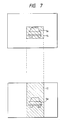
- the road is uneven or sloped, and therefore both the first car on which the device is installed, and the second car 5 under measurement running ahead of the first car bounce or vibrate. If, in this case, the vibration is large, then sometimes the window is laterally shifted with respect to the image 5a of the second car under measurement as indicated at 14a in FIG. 4. In order to eliminate this difficulty, it is necessary to correct the position of the window 14a so that the latter 14a includes the second car's image 15 at the middle at all times. In order to correct the position of the window 14, similarly as in the case of displacing the window which has been set manually, the window is moved so that the right and left parts of the image in the window are symmetrical.
- the range which is searched for the image highest in lateral symmetry thereby to correct the position of the window 14, is determined as follows: That is, in the case of changing the position of the window 14 set manually, the ranges 2k are provided on both sides of the window are searched as shown in FIG. 5; and in the case of tracking the second car's image with the window 14, the ranges k are searched as shown in FIG. 6.
- the searching ranges employed in the case where the window is manually set is twice as large as that of the searching ranges used in the case where the window 14 tracks the image of the second car running ahead of the first car; however, the invention is not limited thereto or thereby. That is, the searching ranges can be changed freely depending, for instance, on the characteristics of the image tracking device 12.
- the microcomputer 10 reads from the memory 8 a pixel signal in the window 14 which is tracking the image 5a of the second car, and employs it as a reference image signal. Then, the microcomputer 10 makes access to the memory 9 in which the image signal of the upper image sensor 4 has been stored, to select the region corresponding to the window 14; that is, the microcomputer 10, while shifting the image signal of the memory 9 one pixel by one pixel with respect to the aforementioned reference image signal, calculates the sum of the absolute values of the differences between the signals of upper and lower pixels.
- the microcomputer 10 determines the position of the image which matches best with the image in the window 14, while shifting the image signal one pixel by one pixel.
- the region 17 in the memory 9, which corresponds to the position of the window 14, concerns the calculation.
- the amount of shift of the pixel is represented by (n) which is detected when upper and lower pixels are subjected to comparison and the sum of the absolute values of the differences between the signals thereof is minimum
- the window 14 is moved laterally in the display screen, it can be tracked with the window, to continuously detect the distance between the first and second cars.
- window position changing means other means may be employed depending on the characteristics of the image tracking device and those of image signal data. That is, it goes without saying that the above-described method shows only one aspect of the invention.
- the inter-car distance detecting device of the invention comprises: the image sensor for detecting the image of the second car running ahead of the first car on which the device is installed, with one pair of substantially upper and lower optical systems; the display means for displaying the image of the second car which is detected by one of the image sensors; the image tracking means for forming the tracking window to surround the image of the second car, and tracking the image of the second car with the tracking window; distance detecting means for calculating a distance between the first and second cars by detecting the amount of shift between the upper and lower image signals with the image signal in the window as a reference signal; and the position changing means for changing, before tracking the image of the second car with the tracking window is started and while the image of the second car is being tracked with the tracking window, the position of the tracking window surrounding the image of the second car according to image signal data in the tracking window.
- the inter-car distance detecting device of the invention even when a plurality of second cars are running ahead of the first car, the aimed second car is indicated by the tracking window, and therefore the operator can detect the second car with ease the image of which is being tracked to detect the distance thereto. Furthermore, the position of the window set manually by the operator can be changed, with the result that setting the window can be achieved quickly, safely and accurately. In addition, the position of the window can be changed while the image of the second car is being tracked with the window. Therefore, the image of the second car can be tracked with high stability.
Landscapes
- Physics & Mathematics (AREA)
- Engineering & Computer Science (AREA)
- Electromagnetism (AREA)
- General Physics & Mathematics (AREA)
- Radar, Positioning & Navigation (AREA)
- Remote Sensing (AREA)
- Multimedia (AREA)
- Measurement Of Optical Distance (AREA)
- Image Processing (AREA)
Claims (5)
- Fahrzeugzwischenabstands-Erfassungseinrichtung zum Messen eines Abstands (R) zwischen einem ersten Fahrzeug (5) und einem zweiten Fahrzeug (5a), welches vor dem ersten Fahrzeug (5) fährt, gemäß dem Prinzip einer trigonometrischen Messung, umfassend die folgenden Merkmale:a) ein Paar von optischen Systemen (1, 2), die zueinander in einem Abstand einer Basislänge (L) liegen;b) ein Paar von Bildsensoren, (3, 4), die entsprechend zu dem optischen System (1, 2) vorgesehen sind und auf denen ein Bild des zweiten Fahrzeugs (5a) durch das optische System (1, 2) fokussiert wird, um ein Bildsignal bereitzustellen;c) eine Einrichtung (7 - 11) zum Anzeigen des Bildes des zweiten Fahrzeugs, welches von einem der Bildsensoren (3, 4) erfaßt worden ist;d) eine Einrichtung (10, 12) zum Bilden eines Verfolgungsfensters (14), welches das Bild des zweiten Fahrzeugs (5a) umgibt, und zum Verfolgen des Bilds (5a) des zweiten Fahrzeugs mit dem Verfolgungsfenster (14);e) eine Einrichtung (10) zum Erfassen des Verschiebebetrags in den Bildsignalen der Bildsensoren mit einem Bildsignal in dem Fenster als ein Referenzsignal, um einen Abstand zwischen dem ersten und dem zweiten (5a) Fahrzeug zu berechnen;f) eine Einrichtung zum Korrigieren (14a -> 14b) der Position des Verfolgungsfensters (14a), welches das Bild des zweiten Fahrzeugs (5a) umgibt, gemäß der Bildsignaldaten in dem Verfolgungsfenster (14), bevor die Verfolgung des Bilds des zweiten Fahrzeugs mit dem Verfolgungsfenster gestartet wird und während das Bild des zweiten Fahrzeugs mit dem Verfolgungsfenster (14) verfolgt wird; undg) wobei die Positions-Korrektureinrichtung die Position des Verfolgungsfensters (14) so bewegt, daß die rechten und linken Teile des Bilds in dem Verfolgungsfenster (14) symmetrisch sind.
- Einrichtung nach Anspruch 1, ferner umfassend eine Speichereinrichtung (8, 9) zum Speichern des Bildsignals von den Bildsensoren (3, 4).
- Einrichtung nach Anspruch 1, wobei das Paar von optischen Systemen (1, 2) im wesentlichen vertikal angeordnet sind.
- Einrichtung nach Anspruch 1, ferner umfassend einen Schalter (13), der betreibbar ist, um eine Bildverfolgungseinrichtung (10, 12) durch einen Betreiber vorzugeben.
- Einrichtung nach Anspruch 1, wobei die Positions-Korrektureinrichtung, bevor die Verfolgung des zweiten Fahrzeugs mit dem Verfolgungsfenster gestartet wird, das Verfolgungsfenster (14) durch Verwenden eines ersten Suchbereichs (2k), der auf beiden Seiten des Verfolgungsfensters vorgesehen ist, positioniert, und, wenn das Bild des zweiten Fahrzeugs mit dem Verfolgungsfenster (14) verfolgt wird, das Verfolgungsfenster (14) unter Verwendung eines zweiten Suchbereichs (1k) auf beiden Seiten des Verfolgungsfensters, der kleiner als der erste Suchbereich (2k) ist, positioniert.
Applications Claiming Priority (2)
| Application Number | Priority Date | Filing Date | Title |
|---|---|---|---|
| JP21683691A JPH0552561A (ja) | 1991-08-28 | 1991-08-28 | 車間距離検出装置 |
| JP216836/91 | 1991-08-28 |
Publications (3)
| Publication Number | Publication Date |
|---|---|
| EP0529558A2 EP0529558A2 (de) | 1993-03-03 |
| EP0529558A3 EP0529558A3 (de) | 1993-04-28 |
| EP0529558B1 true EP0529558B1 (de) | 1997-04-16 |
Family
ID=16694666
Family Applications (1)
| Application Number | Title | Priority Date | Filing Date |
|---|---|---|---|
| EP19920114393 Expired - Lifetime EP0529558B1 (de) | 1991-08-28 | 1992-08-24 | Entfernungsmesser für Abstand zwischen Fahrzeugen |
Country Status (3)
| Country | Link |
|---|---|
| EP (1) | EP0529558B1 (de) |
| JP (1) | JPH0552561A (de) |
| DE (1) | DE69219037T2 (de) |
Families Citing this family (1)
| Publication number | Priority date | Publication date | Assignee | Title |
|---|---|---|---|---|
| US10679071B2 (en) | 2018-01-10 | 2020-06-09 | International Business Machines Corporation | Capturing digital images during vehicle collisions |
Family Cites Families (2)
| Publication number | Priority date | Publication date | Assignee | Title |
|---|---|---|---|---|
| IT1202534B (it) * | 1987-02-13 | 1989-02-09 | Tecnomare Spa | Apparecchiatura per il rilevamento in continuo della distanza da essa di un punto prefissato,anche mobile |
| JP2570315B2 (ja) * | 1987-09-01 | 1997-01-08 | アイシン精機株式会社 | 車上距離検出装置 |
-
1991
- 1991-08-28 JP JP21683691A patent/JPH0552561A/ja active Pending
-
1992
- 1992-08-24 EP EP19920114393 patent/EP0529558B1/de not_active Expired - Lifetime
- 1992-08-24 DE DE1992619037 patent/DE69219037T2/de not_active Expired - Fee Related
Also Published As
| Publication number | Publication date |
|---|---|
| DE69219037T2 (de) | 1997-08-28 |
| JPH0552561A (ja) | 1993-03-02 |
| EP0529558A2 (de) | 1993-03-03 |
| EP0529558A3 (de) | 1993-04-28 |
| DE69219037D1 (de) | 1997-05-22 |
Similar Documents
| Publication | Publication Date | Title |
|---|---|---|
| US7283646B2 (en) | Image processing system using rotatable surveillance camera | |
| EP0510363B1 (de) | Abstandsmessgerät | |
| KR930004880B1 (ko) | 추미식 차간거리 측정장치 | |
| JPH05296767A (ja) | 車間距離検出装置 | |
| US5168355A (en) | Apparatus for detecting distance between cars | |
| JPH0812072B2 (ja) | 距離測定装置 | |
| US5187537A (en) | Vehicle following apparatus | |
| JP2800530B2 (ja) | 車間距離検出装置 | |
| JP2635246B2 (ja) | 先行車追尾用車間距離検出装置 | |
| JPH07119606B2 (ja) | 追尾式車間距離検出装置 | |
| JP2536986B2 (ja) | 車間距離検出装置 | |
| JPH10267618A (ja) | 距離計測装置 | |
| EP0529558B1 (de) | Entfernungsmesser für Abstand zwischen Fahrzeugen | |
| EP0498416B1 (de) | Abstandsdetektionsvorrichtung zwischen Fahrzeugen | |
| JP2635232B2 (ja) | 車間距離検出装置 | |
| JP2560147B2 (ja) | 車間距離検出装置 | |
| JP2827682B2 (ja) | 車間距離検出装置 | |
| JP2730682B2 (ja) | 画像処理装置 | |
| JPH10170226A (ja) | 車両用走行区分帯検出装置 | |
| JPH04262500A (ja) | 車間距離検出装置 | |
| JPH06109467A (ja) | 距離検出装置 | |
| JPH0443911A (ja) | 車間距離検出装置 | |
| JPH02232512A (ja) | 距離測定装置 | |
| JPH05280974A (ja) | 車間距離検出装置 | |
| JPH06229758A (ja) | 車両用障害物検出装置 |
Legal Events
| Date | Code | Title | Description |
|---|---|---|---|
| PUAI | Public reference made under article 153(3) epc to a published international application that has entered the european phase |
Free format text: ORIGINAL CODE: 0009012 |
|
| AK | Designated contracting states |
Kind code of ref document: A2 Designated state(s): DE FR GB |
|
| PUAL | Search report despatched |
Free format text: ORIGINAL CODE: 0009013 |
|
| AK | Designated contracting states |
Kind code of ref document: A3 Designated state(s): DE FR GB |
|
| RIN1 | Information on inventor provided before grant (corrected) |
Inventor name: KARASUDANI, KEIKO, C/O MITSUBISHI DENKI K.K. |
|
| 17P | Request for examination filed |
Effective date: 19930709 |
|
| 17Q | First examination report despatched |
Effective date: 19950710 |
|
| GRAG | Despatch of communication of intention to grant |
Free format text: ORIGINAL CODE: EPIDOS AGRA |
|
| GRAH | Despatch of communication of intention to grant a patent |
Free format text: ORIGINAL CODE: EPIDOS IGRA |
|
| GRAH | Despatch of communication of intention to grant a patent |
Free format text: ORIGINAL CODE: EPIDOS IGRA |
|
| GRAA | (expected) grant |
Free format text: ORIGINAL CODE: 0009210 |
|
| AK | Designated contracting states |
Kind code of ref document: B1 Designated state(s): DE FR GB |
|
| REF | Corresponds to: |
Ref document number: 69219037 Country of ref document: DE Date of ref document: 19970522 |
|
| ET | Fr: translation filed | ||
| REG | Reference to a national code |
Ref country code: GB Ref legal event code: 727 |
|
| REG | Reference to a national code |
Ref country code: GB Ref legal event code: 727A |
|
| PLBE | No opposition filed within time limit |
Free format text: ORIGINAL CODE: 0009261 |
|
| STAA | Information on the status of an ep patent application or granted ep patent |
Free format text: STATUS: NO OPPOSITION FILED WITHIN TIME LIMIT |
|
| REG | Reference to a national code |
Ref country code: GB Ref legal event code: 727B Ref country code: GB Ref legal event code: SP |
|
| 26N | No opposition filed | ||
| REG | Reference to a national code |
Ref country code: GB Ref legal event code: IF02 |
|
| PGFP | Annual fee paid to national office [announced via postgrant information from national office to epo] |
Ref country code: FR Payment date: 20060808 Year of fee payment: 15 |
|
| PGFP | Annual fee paid to national office [announced via postgrant information from national office to epo] |
Ref country code: DE Payment date: 20060817 Year of fee payment: 15 |
|
| PGFP | Annual fee paid to national office [announced via postgrant information from national office to epo] |
Ref country code: GB Payment date: 20060823 Year of fee payment: 15 |
|
| GBPC | Gb: european patent ceased through non-payment of renewal fee |
Effective date: 20070824 |
|
| REG | Reference to a national code |
Ref country code: FR Ref legal event code: ST Effective date: 20080430 |
|
| PG25 | Lapsed in a contracting state [announced via postgrant information from national office to epo] |
Ref country code: DE Free format text: LAPSE BECAUSE OF NON-PAYMENT OF DUE FEES Effective date: 20080301 |
|
| PG25 | Lapsed in a contracting state [announced via postgrant information from national office to epo] |
Ref country code: FR Free format text: LAPSE BECAUSE OF NON-PAYMENT OF DUE FEES Effective date: 20070831 |
|
| PG25 | Lapsed in a contracting state [announced via postgrant information from national office to epo] |
Ref country code: GB Free format text: LAPSE BECAUSE OF NON-PAYMENT OF DUE FEES Effective date: 20070824 |