EP0529324A2 - Einrichtung zum Nachweis der Anwesenheit und der Güte einer Flamme durch Erfassung von elektromagnetischen Strahlungen - Google Patents
Einrichtung zum Nachweis der Anwesenheit und der Güte einer Flamme durch Erfassung von elektromagnetischen Strahlungen Download PDFInfo
- Publication number
- EP0529324A2 EP0529324A2 EP92112779A EP92112779A EP0529324A2 EP 0529324 A2 EP0529324 A2 EP 0529324A2 EP 92112779 A EP92112779 A EP 92112779A EP 92112779 A EP92112779 A EP 92112779A EP 0529324 A2 EP0529324 A2 EP 0529324A2
- Authority
- EP
- European Patent Office
- Prior art keywords
- radiation
- head piece
- fiber bundle
- bundle
- input head
- Prior art date
- Legal status (The legal status is an assumption and is not a legal conclusion. Google has not performed a legal analysis and makes no representation as to the accuracy of the status listed.)
- Granted
Links
Images


Classifications
-
- G—PHYSICS
- G01—MEASURING; TESTING
- G01J—MEASUREMENT OF INTENSITY, VELOCITY, SPECTRAL CONTENT, POLARISATION, PHASE OR PULSE CHARACTERISTICS OF INFRARED, VISIBLE OR ULTRAVIOLET LIGHT; COLORIMETRY; RADIATION PYROMETRY
- G01J5/00—Radiation pyrometry, e.g. infrared or optical thermometry
- G01J5/60—Radiation pyrometry, e.g. infrared or optical thermometry using determination of colour temperature
- G01J5/602—Radiation pyrometry, e.g. infrared or optical thermometry using determination of colour temperature using selective, monochromatic or bandpass filtering
-
- F—MECHANICAL ENGINEERING; LIGHTING; HEATING; WEAPONS; BLASTING
- F23—COMBUSTION APPARATUS; COMBUSTION PROCESSES
- F23N—REGULATING OR CONTROLLING COMBUSTION
- F23N5/00—Systems for controlling combustion
- F23N5/02—Systems for controlling combustion using devices responsive to thermal changes or to thermal expansion of a medium
- F23N5/08—Systems for controlling combustion using devices responsive to thermal changes or to thermal expansion of a medium using light-sensitive elements
- F23N5/082—Systems for controlling combustion using devices responsive to thermal changes or to thermal expansion of a medium using light-sensitive elements using electronic means
-
- G—PHYSICS
- G01—MEASURING; TESTING
- G01J—MEASUREMENT OF INTENSITY, VELOCITY, SPECTRAL CONTENT, POLARISATION, PHASE OR PULSE CHARACTERISTICS OF INFRARED, VISIBLE OR ULTRAVIOLET LIGHT; COLORIMETRY; RADIATION PYROMETRY
- G01J3/00—Spectrometry; Spectrophotometry; Monochromators; Measuring colours
- G01J3/02—Details
- G01J3/0205—Optical elements not provided otherwise, e.g. optical manifolds, diffusers, windows
- G01J3/0218—Optical elements not provided otherwise, e.g. optical manifolds, diffusers, windows using optical fibers
-
- G—PHYSICS
- G01—MEASURING; TESTING
- G01J—MEASUREMENT OF INTENSITY, VELOCITY, SPECTRAL CONTENT, POLARISATION, PHASE OR PULSE CHARACTERISTICS OF INFRARED, VISIBLE OR ULTRAVIOLET LIGHT; COLORIMETRY; RADIATION PYROMETRY
- G01J5/00—Radiation pyrometry, e.g. infrared or optical thermometry
- G01J5/0014—Radiation pyrometry, e.g. infrared or optical thermometry for sensing the radiation from gases, flames
-
- G—PHYSICS
- G01—MEASURING; TESTING
- G01J—MEASUREMENT OF INTENSITY, VELOCITY, SPECTRAL CONTENT, POLARISATION, PHASE OR PULSE CHARACTERISTICS OF INFRARED, VISIBLE OR ULTRAVIOLET LIGHT; COLORIMETRY; RADIATION PYROMETRY
- G01J5/00—Radiation pyrometry, e.g. infrared or optical thermometry
- G01J5/02—Constructional details
- G01J5/08—Optical arrangements
- G01J5/0801—Means for wavelength selection or discrimination
-
- G—PHYSICS
- G01—MEASURING; TESTING
- G01J—MEASUREMENT OF INTENSITY, VELOCITY, SPECTRAL CONTENT, POLARISATION, PHASE OR PULSE CHARACTERISTICS OF INFRARED, VISIBLE OR ULTRAVIOLET LIGHT; COLORIMETRY; RADIATION PYROMETRY
- G01J5/00—Radiation pyrometry, e.g. infrared or optical thermometry
- G01J5/02—Constructional details
- G01J5/08—Optical arrangements
- G01J5/0818—Waveguides
- G01J5/0821—Optical fibres
-
- F—MECHANICAL ENGINEERING; LIGHTING; HEATING; WEAPONS; BLASTING
- F23—COMBUSTION APPARATUS; COMBUSTION PROCESSES
- F23N—REGULATING OR CONTROLLING COMBUSTION
- F23N2229/00—Flame sensors
Definitions
- the detection element (11) may be necessary to arrange the detection element (11) in the immediate vicinity of the flame inside the combustion chamber (Fig. 1-A).
- the transmission and separation element has a corresponding length ( device in a stretched design ) and contains all of the above-mentioned components.
- the sensing element (11) may be located away from the flame and, accordingly, the transmission and separating element may be of a minimal length ( compact design ) and all of the above components, such as 12, are shown in FIG the exit and separation point (123) united.
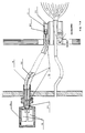
- the sensing element is attached to the body of the burner and the typical setup scheme is shown in Fig. 1-A; therein 11 denote the detection element and 12 the transmission element, which is composed of the entry point 121, the separation point 123 and the intermediate bundle 122, which is provided with a flexible jacket 15, and leads to a container 14 in which the sensors and the associated ones Amplifier circuits 13 are included.
- the device in a compact design is attached directly to the wall of the combustion chamber and the typical installation diagram is shown in FIG. 1-B, where the detection and bundling element 11 is evidently in the immediate vicinity of the exit and separation point 123, which also does the work here the entry point and the transmission element takes over.
- the mutual position of the lens 111 and the input head piece 121 of the fiber bundle is secured by the bush 23.
- Two fixing members 241 and 242 fix the lens and the head piece in the predetermined position.
- the structure of the input head piece 121 is shown in detail in FIG. 3.
- This head piece is constructed in such a way that it can withstand operating temperatures of approximately 300 ° C and peak temperatures of 450 ° C, as well as mechanical loads which can be attributed to a swivel designated by - ⁇ to + ⁇ in Fig. 1-A.
- the pivoting is rigidly coupled to the movement of the burner body, so that there is no slippage between the fiber bundle 122 and the protective sleeve. This property ensures that the end face of the fiber bundle always remains in the focal point of the lens (FIG. 2) and continuously receives the highest possible proportion of the energy emitted by the flame and collected by the lens.
- a liquid, fast-curing binder 25 is then poured into the space between the fiber bundle thus deformed and the holding and protective sleeve 21, which, after solidification, fixes the fiber bundle in the desired position and at the same time prevents the above-mentioned slippage.
- the radiation is transmitted via the said optical fiber bundle 122.
- optical fibers available on the market have different radiation yields depending on the wavelength of the radiation and, accordingly, the fiber bundle is built up with fibers whose properties are either the same or different depending on the wavelengths to be evaluated as desired.
- optical fibers are used for the transmission of ultraviolet or visible or infrared light signals.
- the fibers with different light conductivity are separated at the output end of the fiber bundle (FIG. 4), which is intended for use at ambient temperature.
- a cylindrical metallic hollow body 123 (FIG. 4) is provided, in the bottom of which openings are provided. The latter are used to hold the individual components of the optical fiber bundle (two components of which are designated 33 and 34 respectively), each with homogeneous fibers and from component to component of different optical conductivity.
- the separating element 123 provided for optical separation also serves to shut off the fuel gases which could otherwise get from the interior of the combustion chamber into the container 14 (FIG. 5) which contains the sensors and the associated amplifier circuits.
- This barrier prevents an explosion of fuel gas inside the container 14.
- the cylindrical hollow body 123 is completely filled with a liquid fast-curing binder 35.
- the hollow body 123 receiving and separating the optical fibers thus becomes a cylindrical solid body.
- the complete gas-tight shut-off is achieved by inserting an elastic seal 31 (FIG. 5) between the body 123 and the container 14.
- the body 123 and the associated seal 31 are fixed with the aid of a threaded ring 32.
Landscapes
- Physics & Mathematics (AREA)
- Spectroscopy & Molecular Physics (AREA)
- General Physics & Mathematics (AREA)
- Engineering & Computer Science (AREA)
- Chemical & Material Sciences (AREA)
- Combustion & Propulsion (AREA)
- Mechanical Engineering (AREA)
- General Engineering & Computer Science (AREA)
- Photometry And Measurement Of Optical Pulse Characteristics (AREA)
- Control Of Combustion (AREA)
- Investigating, Analyzing Materials By Fluorescence Or Luminescence (AREA)
Abstract
Description
- Die vorliegende Erfindung betrifft eine Einrichtung zum Nachweis der Anwesenheit und der Güte einer Flamme mit
- 1. einem Erfassungs- und Bündelungselement (11) für die elektromagnetischen Strahlungen der Flamme, bestehend aus einem Linsensystem und einer entsprechenden Halterung,
- 2. einem Übertragungs- und Trennelement (12) für die Strahlungen, bestend aus einer Strahlungseingangsstelle (121), einem Lichtleitfaserbündel (122) und einer Ausgangs- und Trennstelle (123),
- 3. einem mit dem soeben genannten Element integrierten Element zur Abdichtung der Brennkammer gegenüber der elektrischen Schaltung der Einrichtung, bestehend aus derselben mit flüssigem ausgehärteten Bindemittel ausgegossenen Ausgangs- und Trennstelle (123),
- 4. einem in einem metallischen Behälter (14) enthaltenen Element zur Messung und Auswertung der erfassten Strahlungen (13), bestehend aus entsprechenden Sensoren und elektronischen Schaltungen.
- In Abhängigkeit von der Ausbildung und den Raumverhältnissen der Brennkammer kann es notwendig sein, das Erfassungselement (11) in unmittelbarer Nachbarschaft der Flamme im Inneren der Brennkammer anzuordnen (Fig. 1-A).
- In einem solchen Fall weist das Übertragungs- und Trennelement eine entsprechende Länge auf (Einrichtung in gestreckter Ausführung) und enthält alle obengenannte Bestandteile.
- In anderen Fällen (Fig. 1-B) kann das Erfassungselement (11) von der Flamme entfernt angeordnet sein und dementsprechend kann das Übertragungs- und Trennelement eine minimale Länge aufweisen (Einrichtung in gedrängter Ausführung) und alle obengenannten Bestandteile, wie 12, werden in der Ausgangs- und Trennstelle (123) vereinigt.
- Bei der Einrichtung in gestreckter Ausführung wird das Erfassungselement am Körper des Brenners angebracht und das typische Einrichtungsschema ist in Fig. 1-A wiedergegeben; darin bezeichnen 11 das Erfassungselement und 12 das Übertragungselement, welches sich aus der Eingangsstelle 121, der Trennstelle 123 und dem dazwischenliegenden Bündel 122 zusammensetzt, das mit einem biegsamen Mantel 15 versehen ist, und zu einem Behälter 14 führt, in welchem die Sensoren und die dazugehörigen Verstärkerschaltungen 13 enthalten sind.
- Die Einrichtung in gedrängter Ausführung wird unmittelbar an der Wand der Brennkammer angebracht und das typische Einrichtungsschema ist in Figur 1-B wiedergegeben, wo das Erfassungs- und Bündelungselement 11 sich ersichtlich in unmittelbarer Nachbarschaft der Ausgangs- und Trennstelle 123 befindet, welche hier auch die Aufgaben der Eingangsstelle und des Übertragungselementes übernimmt.
- Der Erfindung liegen folgende Aufgaben zugrunde:
- Erfassung durch die Flamme eines Brenners emittierter Strahlungen mit Hilfe eines in der Nähe der Flamme angeordneten optischen Elementes, bei Betriebstemperaturen von etwa 300°C und bei einer Spitzentemperatur von 450°C;
- Fernübertragung der Strahlungen über ein Faserbündel, so dass eine Übertragung elektromagnetischer Strahlungen mit optimalem Wirkungsgrad in Abhängigkeit von der gewünschten Wellenlänge erzielt wird;
- Trennung von Strahlungen verschiedener Wellenlänge durch eine Kombination von unterschiedlichen Lichtleitfasern und/oder optischen Filtern und/oder Sensoren, die für verschiedene Wellenlängenbereiche ausgelegt sind;
- Aufnahme der Strahlungen verschiedener Wellenlänge gesondert an getrennten Sensoren, die in der Lage sind, die Energieausstrahlung der Flamme in den verschiedenen Bereichen der Wellenlänge und der Modulation auszuwerten;
- vergleichende Auswertung der Strahlungen mit verschiedenen Wellenlängen und verschiedenen Modulationsfrequenzen, zum Nachweis der Anwesenheit und der Güte der Flamme, sowie der eventuellen Abweichung von der optimalen Güte.
- Zur Erfüllung der genannten Aufgaben weist die eingangserwähnte Einrichtung erfindungsgemäss nachstehende kennzeichnenden Merkmale auf:
- das Erfassungselement besteht im wesentlichen in einer Sammellinse, welche die zur Bewertung der Verbrennung dienenden Nutzstrahlungen im Bereich ihres "geometrischen" Brennpunktes bündelt; in diesem Brennpunkt ist das Eingangskopfstück eines das Übertragungs- und Trennelement bildenden Lichtleitfaserbündels angeordnet und fixiert;
- das Übertragungs- und Trennelement ist durch Lichtleitfasern gebildet, deren Strahlungsausbeuten den zur Auswertung bestimmten Wellenlängen angepasst sind, wobei diese Lichtleitfasern am ausgangsseitigen Ende in einem Trennelement voneinander getrennt sind;
- das Trennelement besitzt Mittel für die mechanische Fixierung der Fasern, für deren Führung zu den strahlungsempfindlichen Sensoren und für die abgedichtete Trennung der Brennkammer von der elektrischen Schaltung der Einrichtung.
- Diese und weitere den Patentansprüchen entnehmbaren Merkmale werden nachstehend unter Bezugnahme auf die beiliegenden schematischen Zeichnungen anhand eines Ausführungsbeispiels für die Erfindung, auf welches letztere nicht beschränkt ist, näher erläutert.
- In den Zeichnungen zeigen:
- Figur 1-A und 1-B
- die bereits weiter oben beschriebenen schematischen Ausführungen der Einrichtung,
- Figur 2
- ein Beispiel für das erfindungsgemässe Erfassungselement,
- Figur 3
- eine Einzelheit des erfindungsgemässen Eingangskopfstückes des Lichtleitfaserbündels,
- Figur 4
- ein erfindungsgemässes Trennelement,
- Figur 5
- die Verwendung des Trennelementes zum Absperren der aus dem Inneren der Brennkammer herrührenden Brenngase (51 = Einrichtung in gestreckter Ausführung; 52 = Einrichtung in gedraengter Ausfuehrung).
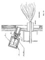
- Das in der Nähe der Flamme angeordnete Erfassungselement 11 für die Strahlungen ist im Ausführungsbeispiel in Fig. 2 näher dargestellt. Es besteht im wesentlichen aus zwei Teilen:
- einer Sammellinse 111, deren Fläche die Aufnahme einer gewünschten Energiemenge ermöglicht und deren Wölbung derart ausgelegt ist, dass die Linse, unter Berücksichtigung der Aberration, sämtliche der Bewertung der Verbrennung dienende Nutzstrahlungen, nämlich ulttaviolette (Wellenlänge 190 - 300 nm) bis sichtbare (400 - 750 nm) und bis infrarote Nutzstrahlungen (800 - 2500 nm), im Bereich ihres "geometrischen" Brennpunktes auf eine Fläche von höchstens 3,5 mm² bündelt;
- einer Schutzbüchse 23, welche das Eingangskopfstück 121 im geometrischen Brennpunkt der Linse 111 aufnimmt.
- Die gegenseitige Lage der Linse 111 und des Eingangskopfstückes 121 des Faserbündels ist durch die Büchse 23 gesichert.
- Zwei Fixierglieder 241 und 242 fixieren die Linse und das Kopfstück in der vorbestimmten Lage.
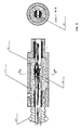
- Der Aufbau des Eingangskopfstückes 121 ist im einzelnen in Fig. 3 dargestellt. Dieses Kopfstück ist derart aufgebaut, dass es Betriebstemperaturen von etwa 300 °C und Spitzentemperaturen von 450°C, sowie mechanische Belastungen aushalten kann, die auf eine in Fig. 1-A mit - α bis + α bezeichnete Schwenkung zurückzuführen sind. Die Schwenkung ist mit der Bewegung des Brennerkörpers starr gekuppelt, so dass zwischen dem Faserbündel 122 und der Schutzbüchse kein Schlupf entsteht. Durch diese Eigenschaft wird gewährleistet, dass die Endfläche des Faserbündels stets im Brennpunkt der Linse (Fig. 2) verbleibt und dauernd den höchstmöglichen Anteil der von der Flamme ausgestrahlten und von der Linse gesammelten Energie erhält.
- Dies wird durch ein im kalten Zustand in das Innere des Faserbündels 122 eingefügtes Spreizglied 22 erzielt, das die Fasern voneinander entfernt und damit eine Stelle mit erweitertem Bündeldurchmesser bildet.
- In den Zwischenraum zwischen dem derart verformten Faserbündel und der Halterungs- und Schutzbüchse 21 wird sodann ein flüssiges schnellhärtendes Bindemittel 25 unter Druck eingegossen, welches nach erfolgter Erstarrung das Faserbündel in der gewünschten Lage fixiert und dabei gleichzeitig den obenerwähnten Schlupf verhindert.
- Die Übertragung der Strahlungen erfolgt über das genannte Lichtleitfaserbündel 122.
- Die auf dem Markt erhältlichen Lichtleitfasern weisen je nach der Wellenlänge der Strahlungen unterschiedliche Strahlungsausbeuten auf und dementsprechend wird das Faserbündel mit solchen Fasern aufgebaut, deren Eigenschaften in Abhängigkeit von den wunschgemäss auszuwertenden Wellenlängen entweder einander gleich oder voneinander verschieden sind.
- Im vorliegenden Ausführungsbeispiel kommen unterschiedliche Lichtleitfasertypen zur Übertragung von ultravioletten bzw. sichtbaren bzw. infraroten Lichtsignalen zur Anwendung.
- Auf diese Weise erhält man eine erste Trennung der Strahlungen.
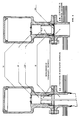
- Die Trennung der Fasern mit unterschiedlicher Lichtleitfähigkeit erfolgt am ausgangsseitigen Ende des Faserbündels (Fig. 4), das zum Einsatz bei der Umgebungstemperatur bestimmt ist.
- Damit die Trennung der Fasern und gleichzeitig deren mechanische Fixierung erzielt wird, ist ein zylinderförmiger metallischer Hohlkörper 123 (Fig. 4) vorgesehen, in dessen Boden Öffnungen vorgesehen sind. Letztere dienen zur Aufnahme der einzelnen Bestandteile des Lichtleitfaserbündels (wovon zwei Bestandteile mit 33 bzw. 34 bezeichnet sind) mit jeweils untereinander homogenen Fasern und von Bestandteil zu Bestandteil unterschiedlicher Lichtleitfähigkeit.
- Das zur optischen Trennung vorgesehene Trennelement 123 dient auch zum Absperren der Brenngase, die sonst aus dem Inneren der Brennkammer in den Behälter 14 (Fig. 5) gelangen könnten, welcher die Sensoren und die dazugehörigen Verstärkerschaltungen enthält.
- Diese Absperrung verhindert eine Explosion von Brenngas im Inneren des Behälters 14.
- Um dieses Ergebnis zu erzielen wird der zylindrische Hohlkörper 123 mit einem flüssigen schnellhärtenden Bindemittel 35 vollkommen gefüllt. Der die Lichtleitfasen aufnehmende und trennende Hohlkörper 123 wird somit zu einem zylindrischen Vollkörper.
- Die vollkommene gasdichte Absperrung wird durch Einfügung einer elastischen Dichtung 31 (Fig. 5) zwischen dem Körper 123 und dem Behälter 14 erzielt.
- Die Fixierung des Körpers 123 und der zugeordneten Dichtung 31 erfolgt mit Hilfe eines Gewinderinges 32.
Claims (8)
Einrichtung nach Anspruch 1, dadurch gekennzeichnet, dass das Trennelement (123) durch einen metallischen Hohlkörper gebildet ist, in welchem einerseits eine Öffnung zur Aufnahme des Lichtleitfaserbündels (122) und andererseits Öffnungen zur Aufnahme der einzelnen, getrennten Bestandteile (33, 34) des Bündels vorgesehen sind.
Applications Claiming Priority (2)
| Application Number | Priority Date | Filing Date | Title |
|---|---|---|---|
| ITMI912292A IT1251246B (it) | 1991-08-27 | 1991-08-27 | Dispositivo per a rivelazione della presenza e della qualita' della fiamma attraverso la captazione e l'analisi di radiazioni elettromagnetiche di diversa lunghezza d'onda |
| ITMI912292 | 1991-08-27 |
Publications (3)
| Publication Number | Publication Date |
|---|---|
| EP0529324A2 true EP0529324A2 (de) | 1993-03-03 |
| EP0529324A3 EP0529324A3 (en) | 1994-11-17 |
| EP0529324B1 EP0529324B1 (de) | 1998-12-02 |
Family
ID=11360582
Family Applications (1)
| Application Number | Title | Priority Date | Filing Date |
|---|---|---|---|
| EP92112779A Expired - Lifetime EP0529324B1 (de) | 1991-08-27 | 1992-07-27 | Einrichtung zum Nachweis der Anwesenheit und der Güte einer Flamme durch Erfassung von elektromagnetischen Strahlungen |
Country Status (6)
| Country | Link |
|---|---|
| US (1) | US5317165A (de) |
| EP (1) | EP0529324B1 (de) |
| AT (1) | ATE174120T1 (de) |
| CA (1) | CA2076401A1 (de) |
| DE (1) | DE59209576D1 (de) |
| IT (1) | IT1251246B (de) |
Cited By (2)
| Publication number | Priority date | Publication date | Assignee | Title |
|---|---|---|---|---|
| DE19809792A1 (de) * | 1998-03-09 | 1999-09-23 | Fraunhofer Ges Forschung | Vorrichtung zum Untersuchen eines Mediums |
| EP3255398A1 (de) * | 2016-06-08 | 2017-12-13 | General Electric Technology GmbH | System, verfahren und vorrichtung zur anpassung eines flammenfühlers |
Families Citing this family (23)
| Publication number | Priority date | Publication date | Assignee | Title |
|---|---|---|---|---|
| NL9100822A (nl) * | 1991-05-13 | 1992-12-01 | Hoogovens Groep Bv | Instrument voor aanwezigheidsbepaling van een lichaam en walserij voorzien van een dergelijk instrument. |
| US5748090A (en) * | 1993-10-19 | 1998-05-05 | The United States Of America As Represented By The Administrator Of The National Aeronautics And Space Administration | Optical flameout detector |
| US5543913A (en) * | 1994-11-21 | 1996-08-06 | Eastman Kodak Company | Device for measuring the spatial characteristics of a light source |
| US5521697A (en) * | 1995-01-25 | 1996-05-28 | Houston Industries Incorporated | Protective cover for fiberoptic scanner head |
| DE19632174C2 (de) | 1996-08-09 | 2002-02-07 | Abb Research Ltd | Temperaturmessverfahren |
| US5961314A (en) * | 1997-05-06 | 1999-10-05 | Rosemount Aerospace Inc. | Apparatus for detecting flame conditions in combustion systems |
| US5986277A (en) * | 1997-10-29 | 1999-11-16 | National Research Council Of Canada | Method and apparatus for on-line monitoring the temperature and velocity of thermally sprayed particles |
| FR2771798B1 (fr) * | 1997-12-02 | 1999-12-31 | Air Liquide | Bruleur oxy-combustible |
| US6652266B1 (en) * | 2000-05-26 | 2003-11-25 | International Thermal Investments Ltd. | Flame sensor and method of using same |
| US7248755B2 (en) * | 2003-03-31 | 2007-07-24 | Zolo Technologies, Inc. | Method and apparatus for the monitoring and control of combustion |
| SE0501840L (sv) * | 2005-08-19 | 2007-02-20 | Aga Ab | Förfarande jämte för övervakning av en brännare |
| US8469700B2 (en) | 2005-09-29 | 2013-06-25 | Rosemount Inc. | Fouling and corrosion detector for burner tips in fired equipment |
| DE102006036563A1 (de) * | 2006-08-04 | 2008-02-07 | Siemens Building Technologies Hvac Products Gmbh | Überwachung von Verbrennungsvorgängen an einem Ort durch schnellen Sauerstoffsensor |
| US8094301B2 (en) * | 2007-12-12 | 2012-01-10 | Gas Technology Institute | Video and thermal imaging system for monitoring interiors of high temperature reaction vessels |
| US7907272B2 (en) * | 2007-12-12 | 2011-03-15 | Gas Technology Institute | Fiber optic spectroscopic digital imaging sensor and method for flame properties monitoring |
| US7987712B2 (en) * | 2008-12-10 | 2011-08-02 | Rosemount Aerospace Inc. | High temperature seal assembly for optical sensor |
| CA2748793C (en) | 2009-01-09 | 2016-06-07 | Michael John Estes | Method and apparatus for monitoring combustion properties in an interior of a boiler |
| US9863813B2 (en) * | 2012-04-13 | 2018-01-09 | General Electric Company | Flame sensor |
| JP6196289B2 (ja) | 2012-04-19 | 2017-09-13 | ゾロ テクノロジーズ,インコーポレイティド | 方向可変の波長可変ダイオードレーザ吸収分光計を有する炉内再帰反射体 |
| US10392959B2 (en) * | 2012-06-05 | 2019-08-27 | General Electric Company | High temperature flame sensor |
| JP3182445U (ja) * | 2012-12-28 | 2013-03-28 | 株式会社島津製作所 | 光学測定用プローブ及びこれを備えた光学測定装置 |
| US9188463B2 (en) * | 2013-02-05 | 2015-11-17 | General Electric Company | Hermetic electrically shielded connector |
| CN107289470B (zh) * | 2016-04-11 | 2019-06-14 | 众智光电科技股份有限公司 | 具有温度感测功能的瓦斯炉 |
Family Cites Families (7)
| Publication number | Priority date | Publication date | Assignee | Title |
|---|---|---|---|---|
| US4037113A (en) * | 1975-04-11 | 1977-07-19 | Forney Engineering Company | Flame detector |
| US4709155A (en) * | 1984-11-22 | 1987-11-24 | Babcock-Hitachi Kabushiki Kaisha | Flame detector for use with a burner |
| SE459446B (sv) * | 1985-02-12 | 1989-07-03 | H Tyr N Carl | Foerfarande foer styrning av en med insprutningsmunstycke foersedd braennare genom optisk oevervakning av flamman samt anordning foer genomfoerande av foerfarandet |
| WO1989012774A1 (en) * | 1988-06-23 | 1989-12-28 | Allied-Signal Inc. | Solid-state optical flame detector |
| US4983853A (en) * | 1989-05-05 | 1991-01-08 | Saskatchewan Power Corporation | Method and apparatus for detecting flame |
| DD299920A7 (de) * | 1989-12-27 | 1992-05-14 | Freiberg Brennstoffinst | Vorrichtung zur optischen ueberwachung von hochtemperaturreaktoren |
| US5164600A (en) * | 1990-12-13 | 1992-11-17 | Allied-Signal Inc. | Device for sensing the presence of a flame in a region |
-
1991
- 1991-08-27 IT ITMI912292A patent/IT1251246B/it active IP Right Grant
-
1992
- 1992-07-27 DE DE59209576T patent/DE59209576D1/de not_active Expired - Fee Related
- 1992-07-27 EP EP92112779A patent/EP0529324B1/de not_active Expired - Lifetime
- 1992-07-27 AT AT92112779T patent/ATE174120T1/de not_active IP Right Cessation
- 1992-08-19 US US07/932,086 patent/US5317165A/en not_active Expired - Fee Related
- 1992-08-19 CA CA002076401A patent/CA2076401A1/en not_active Abandoned
Cited By (5)
| Publication number | Priority date | Publication date | Assignee | Title |
|---|---|---|---|---|
| DE19809792A1 (de) * | 1998-03-09 | 1999-09-23 | Fraunhofer Ges Forschung | Vorrichtung zum Untersuchen eines Mediums |
| DE19809792C2 (de) * | 1998-03-09 | 2000-03-30 | Fraunhofer Ges Forschung | Vorrichtung zur Messung der Emission und/oder Absorption eines heißen Gases oder Plasmas |
| EP3255398A1 (de) * | 2016-06-08 | 2017-12-13 | General Electric Technology GmbH | System, verfahren und vorrichtung zur anpassung eines flammenfühlers |
| CN107477609A (zh) * | 2016-06-08 | 2017-12-15 | 通用电器技术有限公司 | 用于调节火焰监测器的系统、方法和设备 |
| US10067292B2 (en) | 2016-06-08 | 2018-09-04 | General Electric Technology Gmbh | System, method and apparatus for adjusting a flame scanner |
Also Published As
| Publication number | Publication date |
|---|---|
| CA2076401A1 (en) | 1993-02-28 |
| EP0529324B1 (de) | 1998-12-02 |
| US5317165A (en) | 1994-05-31 |
| DE59209576D1 (de) | 1999-01-14 |
| ATE174120T1 (de) | 1998-12-15 |
| ITMI912292A0 (it) | 1991-08-27 |
| IT1251246B (it) | 1995-05-05 |
| ITMI912292A1 (it) | 1993-02-27 |
| EP0529324A3 (en) | 1994-11-17 |
Similar Documents
| Publication | Publication Date | Title |
|---|---|---|
| EP0529324A2 (de) | Einrichtung zum Nachweis der Anwesenheit und der Güte einer Flamme durch Erfassung von elektromagnetischen Strahlungen | |
| DE19821401C2 (de) | Endoskop zur Inspektion eines Beobachtungsraumes | |
| DE10012291C1 (de) | Verfahren zur faseroptischen Temperaturmessung und faseroptischer Temperatursensor | |
| DE3587943T2 (de) | Verbinder für Hochleistungsstrahl. | |
| EP0632259A2 (de) | Vorrichtung zur Feststellung von Undichtigkeiten an Bauteilen | |
| DE4216404A1 (de) | Gasentnahmevorrichtung für ein Rauchgas-Analysegerät | |
| DE102011101108A1 (de) | Transflexionssonde und Transflexionssensor | |
| DE2351922A1 (de) | Vorrichtung zum nachweis von makroteilchen in einem gasstrom | |
| EP0895587B1 (de) | Kapillarhalter | |
| DE4128844A1 (de) | Optischer temperatursensor | |
| DE69124165T2 (de) | Lichtübertragender Stab für einen Funken-Detektor | |
| DE4442524A1 (de) | Verbinderanordnung für ein optisches Faserkabel | |
| DE4014374A1 (de) | Proben-aufnehmer oder proben-analysator zur optischen analyse einer probe | |
| DE3447724A1 (de) | Verfahren zur temperaturmessung in einem hochdruckofen einer isostatischen warmpresse | |
| DE19845512B4 (de) | Vorrichtung zur Erfassung von Vorgängen im Brennraum einer in Betrieb befindlichen Verbrennungskraftmaschine | |
| DE102008054798A1 (de) | Schweißanordnung sowie Schweißverfahren | |
| EP0682778A1 (de) | Elektro-optisches modul. | |
| DE3100082A1 (de) | Vorrichtung und verfahren zum messen bestimmter eigenschaften von gaspartikeln | |
| DE102014104766A1 (de) | Hermetisch abgedichtete Boroskopsondenspitze | |
| DE2301597A1 (de) | Auflicht-beleuchtungseinrichtung | |
| DE3400717A1 (de) | Vorrichtung zur messung des brechungsindex von fluessigkeiten | |
| EP1156310A1 (de) | Optisches Referenzelement und Verfahren zur spektralen Kalibrierung eines optischen Spektrumanalysators | |
| DE4315152A1 (de) | Vorrichtung zur Untersuchung eines Gases | |
| DE4136588C2 (de) | Vorrichtung zum Schutz gegen überhöhte optische Leistungs- und Energiedichten | |
| EP3220132B1 (de) | In-situ-gasmesssystem für gasreaktoren mit kritischen umgebungen |
Legal Events
| Date | Code | Title | Description |
|---|---|---|---|
| PUAI | Public reference made under article 153(3) epc to a published international application that has entered the european phase |
Free format text: ORIGINAL CODE: 0009012 |
|
| AK | Designated contracting states |
Kind code of ref document: A2 Designated state(s): AT BE DE ES FR GB NL |
|
| PUAL | Search report despatched |
Free format text: ORIGINAL CODE: 0009013 |
|
| AK | Designated contracting states |
Kind code of ref document: A3 Designated state(s): AT BE DE ES FR GB NL |
|
| 17P | Request for examination filed |
Effective date: 19950410 |
|
| 17Q | First examination report despatched |
Effective date: 19970520 |
|
| GRAG | Despatch of communication of intention to grant |
Free format text: ORIGINAL CODE: EPIDOS AGRA |
|
| GRAG | Despatch of communication of intention to grant |
Free format text: ORIGINAL CODE: EPIDOS AGRA |
|
| GRAH | Despatch of communication of intention to grant a patent |
Free format text: ORIGINAL CODE: EPIDOS IGRA |
|
| GRAH | Despatch of communication of intention to grant a patent |
Free format text: ORIGINAL CODE: EPIDOS IGRA |
|
| GRAA | (expected) grant |
Free format text: ORIGINAL CODE: 0009210 |
|
| AK | Designated contracting states |
Kind code of ref document: B1 Designated state(s): AT BE DE ES FR GB NL |
|
| PG25 | Lapsed in a contracting state [announced via postgrant information from national office to epo] |
Ref country code: NL Free format text: LAPSE BECAUSE OF FAILURE TO SUBMIT A TRANSLATION OF THE DESCRIPTION OR TO PAY THE FEE WITHIN THE PRESCRIBED TIME-LIMIT Effective date: 19981202 Ref country code: FR Free format text: LAPSE BECAUSE OF FAILURE TO SUBMIT A TRANSLATION OF THE DESCRIPTION OR TO PAY THE FEE WITHIN THE PRESCRIBED TIME-LIMIT Effective date: 19981202 Ref country code: ES Free format text: THE PATENT HAS BEEN ANNULLED BY A DECISION OF A NATIONAL AUTHORITY Effective date: 19981202 |
|
| REF | Corresponds to: |
Ref document number: 174120 Country of ref document: AT Date of ref document: 19981215 Kind code of ref document: T |
|
| REF | Corresponds to: |
Ref document number: 59209576 Country of ref document: DE Date of ref document: 19990114 |
|
| GBT | Gb: translation of ep patent filed (gb section 77(6)(a)/1977) |
Effective date: 19990304 |
|
| EN | Fr: translation not filed | ||
| NLV1 | Nl: lapsed or annulled due to failure to fulfill the requirements of art. 29p and 29m of the patents act | ||
| PGFP | Annual fee paid to national office [announced via postgrant information from national office to epo] |
Ref country code: GB Payment date: 19990709 Year of fee payment: 8 |
|
| PG25 | Lapsed in a contracting state [announced via postgrant information from national office to epo] |
Ref country code: AT Free format text: LAPSE BECAUSE OF NON-PAYMENT OF DUE FEES Effective date: 19990727 |
|
| PG25 | Lapsed in a contracting state [announced via postgrant information from national office to epo] |
Ref country code: BE Free format text: LAPSE BECAUSE OF NON-PAYMENT OF DUE FEES Effective date: 19990731 |
|
| PGFP | Annual fee paid to national office [announced via postgrant information from national office to epo] |
Ref country code: DE Payment date: 19990827 Year of fee payment: 8 |
|
| PLBE | No opposition filed within time limit |
Free format text: ORIGINAL CODE: 0009261 |
|
| STAA | Information on the status of an ep patent application or granted ep patent |
Free format text: STATUS: NO OPPOSITION FILED WITHIN TIME LIMIT |
|
| 26N | No opposition filed | ||
| BERE | Be: lapsed |
Owner name: SIE SYSTEMS S.P.A. Effective date: 19990731 |
|
| PG25 | Lapsed in a contracting state [announced via postgrant information from national office to epo] |
Ref country code: GB Free format text: LAPSE BECAUSE OF NON-PAYMENT OF DUE FEES Effective date: 20000727 |
|
| GBPC | Gb: european patent ceased through non-payment of renewal fee |
Effective date: 20000727 |
|
| PG25 | Lapsed in a contracting state [announced via postgrant information from national office to epo] |
Ref country code: DE Free format text: LAPSE BECAUSE OF NON-PAYMENT OF DUE FEES Effective date: 20010501 |