EP0528892B1 - Process and device for packing pressed bales - Google Patents
Process and device for packing pressed bales Download PDFInfo
- Publication number
- EP0528892B1 EP0528892B1 EP91909195A EP91909195A EP0528892B1 EP 0528892 B1 EP0528892 B1 EP 0528892B1 EP 91909195 A EP91909195 A EP 91909195A EP 91909195 A EP91909195 A EP 91909195A EP 0528892 B1 EP0528892 B1 EP 0528892B1
- Authority
- EP
- European Patent Office
- Prior art keywords
- foil
- arm
- reel
- film
- casing
- Prior art date
- Legal status (The legal status is an assumption and is not a legal conclusion. Google has not performed a legal analysis and makes no representation as to the accuracy of the status listed.)
- Expired - Lifetime
Links
- 238000000034 method Methods 0.000 title claims abstract description 17
- 238000012856 packing Methods 0.000 title claims abstract description 8
- 239000011888 foil Substances 0.000 claims abstract description 52
- 238000004804 winding Methods 0.000 abstract 2
- 238000004806 packaging method and process Methods 0.000 description 16
- 238000010276 construction Methods 0.000 description 3
- 238000012858 packaging process Methods 0.000 description 3
- 238000003466 welding Methods 0.000 description 3
- 239000000463 material Substances 0.000 description 2
- 238000006243 chemical reaction Methods 0.000 description 1
- 238000005253 cladding Methods 0.000 description 1
- 230000000295 complement effect Effects 0.000 description 1
- 238000011982 device technology Methods 0.000 description 1
- 230000000694 effects Effects 0.000 description 1
- 238000005516 engineering process Methods 0.000 description 1
- 230000002349 favourable effect Effects 0.000 description 1
- 239000000835 fiber Substances 0.000 description 1
- 229920006280 packaging film Polymers 0.000 description 1
- 239000012785 packaging film Substances 0.000 description 1
- 238000012536 packaging technology Methods 0.000 description 1
- 238000000926 separation method Methods 0.000 description 1
- 239000004753 textile Substances 0.000 description 1
- 239000010784 textile waste Substances 0.000 description 1
Images


Classifications
-
- B—PERFORMING OPERATIONS; TRANSPORTING
- B65—CONVEYING; PACKING; STORING; HANDLING THIN OR FILAMENTARY MATERIAL
- B65B—MACHINES, APPARATUS OR DEVICES FOR, OR METHODS OF, PACKAGING ARTICLES OR MATERIALS; UNPACKING
- B65B27/00—Bundling particular articles presenting special problems using string, wire, or narrow tape or band; Baling fibrous material, e.g. peat, not otherwise provided for
- B65B27/12—Baling or bundling compressible fibrous material, e.g. peat
- B65B27/125—Baling or bundling compressible fibrous material, e.g. peat and wrapping or bagging
-
- B—PERFORMING OPERATIONS; TRANSPORTING
- B65—CONVEYING; PACKING; STORING; HANDLING THIN OR FILAMENTARY MATERIAL
- B65B—MACHINES, APPARATUS OR DEVICES FOR, OR METHODS OF, PACKAGING ARTICLES OR MATERIALS; UNPACKING
- B65B11/00—Wrapping, e.g. partially or wholly enclosing, articles or quantities of material, in strips, sheets or blanks, of flexible material
- B65B11/02—Wrapping articles or quantities of material, without changing their position during the wrapping operation, e.g. in moulds with hinged folders
- B65B11/025—Wrapping articles or quantities of material, without changing their position during the wrapping operation, e.g. in moulds with hinged folders by webs revolving around stationary articles
Definitions
- the invention relates to a method and an apparatus for packaging bales with the features in the preamble of the main method and device claim.
- the wrapping device consists of two fixed support arms and two swiveling film arms.
- the film arms are cantilevered at one end and carry the heavy film wrap and a welding and cutting device at the other end.
- the complete wrapping device sits on a single transport cart and is moved from the side into the baling or packaging station at the level of the baling bale.
- the jacket film stretched between the rigid support arms and the film roll is wrapped around the press bale, the pivotable film arms performing an additional rotary movement with the film roll.
- Such an arrangement poses mechanical and kinematic problems.
- the film ends will be firmly connected to one another at the connection point by welding, stapling or in some other way.
- the invention solves this problem with the features in the main method and device claim.
- the heavy film wrap is moved in a simple manner, preferably on a straight path, along the press bale.
- the problems of the prior art with the kinematics, the mechanics and the stability of the device can hereby be avoided.
- the U-shaped enveloping movement of the jacket film is carried out by the easier to handle film arm, which can also be dimensioned relatively weak due to the low weight of the film piece pulled off.
- strapping can take place immediately after the baling of the press.
- the strapping device can be combined with the wrapping device or immediately follow it.
- the wrapping device does not have to be removed in a time-consuming and space-consuming manner before the strapping device can take action. Rather, the two devices can work together and complement each other in terms of function and device technology, thereby optimizing the construction effort.
- the wrapping device remains on the press bale during strapping and holds the jacket film firmly. In this way, the taut and overlapped position of the film ends can be secured until and during the strapping. Packing time and control effort are also saved. It is also favorable that only a simple and no cross-wise strapping of the bale is required for film fixing.
- Another advantage of the packaging technology according to the invention is that the method and device are suitable for different bale sizes and can be adapted by software. This expands the area of application and at the same time reduces the conversion effort.
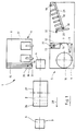
- FIG. 1 shows a packaging device (1) in connection with a baling press (3), here in the form of a two-column carousel baling press known per se.
- a baling press (3) here in the form of a two-column carousel baling press known per se.
- the bale preferably consists of short cut or long textile fibers, the so-called tow. Alternatively, textile waste or other materials can also be used as bale material.
- Figure 1 shows the starting position in which the press box (not shown) has just been pulled off the press bale (2).
- the packaging device (1) is located outside the press space and approximately at the level of the outer press post (4).
- the packaging device (1) consists of a wrapping device (5) and a strapping device (6), both of which are arranged on two transport carriages (8, 9).
- the transport carriages (8, 9) are arranged to be movable on rails or other interconnects on both sides and along the bale (2). They have independent drives and can be moved separately. During the packaging process, they move in the direction of travel (28).
- the wrapping device (5) has a film roll (10) with a downstream dancer (11) as well as a film feeder (12) and a cutting device (13) arranged behind it, which are arranged together on the transport carriage (9).
- the wrapping device (5) also includes a gripping arm (20) which is arranged on a row arrangement of deflection channels (18) of the strapping device (6) so as to be pivotable about a vertical axis (38). These parts are also arranged on the trolley (9).
- the wrapping device (5) also has extendable holding pins (21) (see FIG. 6), which are also located on the transport trolley (9).
- a film arm (15) of the wrapping device (5) with an end gripper (16) is arranged on the opposite transport carriage (8). In the direction of travel (28) there are two strapping heads (17) of the strapping device (6).
- the downstream dancer (11) forms a film store in which the jacket film (7) spans several vertical rollers are connected in a spring-elastic manner. The dancer (11) compensates for film tensions and ensures even removal from the film wrap (10).
- the jacket film (7) then enters the film feeder (12), which is a conveyor and holding device, e.g. has a friction wheel arrangement which can pull off the jacket film from the film roll (10) and hold the film end.
- the cutting device (13) which can be designed as a knife arrangement, fusible wire or in some other suitable manner.
- the cutting device (13) and the film feeder (12) sit in the direction of travel (28) behind the film wrap (10) and are located directly on the edge of the transport carriage (9) on the bale side. They are arranged together on a carrier which is rotatably mounted on the transport carriage (8) about a vertical pivot axis (14) (cf. FIG. 4).
- the deflection channels (18) are arranged at the rear end of the transport carriage (9) in the direction of travel (28). They are rotatably mounted about a vertical axis (19), which is located at the rear end of the carriage and on the bale-side carriage edge.
- the deflection channels (18) are present at least in the same number as the lacing grooves (26) in the press rams (27) and are arranged accordingly.
- the individual deflection channels (18) are connected and held together at the rear by a frame (29) which in turn engages the axis of rotation (19). In the rest position according to FIG. 1, the deflection channels (18) are pivoted back from the bale-side wagon edge.
- the gripper arm (20) is located at the front end of the frame of the deflection channels (18).
- the arm parts (30, 31) consists of a double arm arrangement, the arm parts (30, 31) of which extend transversely to the direction of travel (28) and are spaced apart from one another by more than the film height.
- the arm pieces (30.31) carry vertical and movable tension fingers (32) at the ends, which can grip the horizontal film edges from above or from below.
- the clamping fingers (32) are in turn adjustable in height.
- the film arm (15) is mounted on the trolley (8) so that it can be extended transversely to the direction of travel (28). It consists of a telescopic double-arm arrangement, the arm parts (33, 34) of which also extend transversely to the direction of travel (28) and are at a distance from each other by less than the height of the film.
- the gripper (16) is arranged on the arm ends so as to be pivotable about a vertical axis (35). It consists of two arm extensions (36) that have horizontal tension fingers (37) at the ends, which can grasp and hold the vertical film edge.
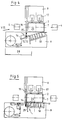
- FIG. 2 shows the sequence of the packaging process.
- both transport carriages (8, 9) move a small distance in the direction of travel (28) until the film arm (15) and the cutting device (13) and the film feed (12) between the press post (4) and the bale ( 2) assume an aligned position.
- the film arm (15) then extends and, with its gripper (6) directed straight ahead, grips the front film end (22) which protrudes a little above the cutting device (13).
- the film arm (15) then moves back to the starting position on the transport carriage (8) and pulls the jacket film (7).
- the trolley (8) then continues until the film arm (15) is just in front of the bale (2).
- the film arm (15) extends again until the swivel joint (35) of the gripper (16) is approximately at the level of the opposite broad side (25) of the press bale (2).
- the other dolly (9) also moves a short distance at the same time or shortly thereafter and thereby places the covering film (7) on the rear bale front.
- the press bale (2) usually has a substantially rectangular cross-sectional shape and extends along the direction of travel (28). With the aforementioned travel and pull-out movements, the jacket film (7) is placed in a lateral U-shape around the two narrow sides and one broad side of the bale (2). The broad side (25) of the bale (2) facing the transport carriage (9) is now still open. In order to still wrap this broad side (25), the transport carriage (9) moves a little further according to FIG. 4 until the axis of rotation (19) is just behind the bale (2). The cutting device (13) and the film feeder (12) pivot automatically about their pivot axis (14) through the film pull and then extend together with the jacket film (7) at an angle to the bale (2).
- the deflection channels (18) now pivot about their axis (19) on the press bales (2), the covering film (7) being placed flat on the broad side (25).
- the deflection channels (18) are aligned with the lacing grooves (26) and are already firmly in their strapping position. They then stop during the strapping process.
- the gripping arm (20) comes to rest on the front bale corner due to the pivoting movement of the frame (29).
- the jacket film (7) and the rear film end (23) are under tension placed on the side surface (25) and held.
- the gripper (16) is then actuated and folds onto the side surface (25), taking the front film end (22) with it. It moves through the free space within the curved deflection channels (18) and under the gripping arm (20) and, under tension, places the front film end (22) on the rear film end (23).
- two or more holding pins (21) now extend and press the front foil end (22) onto the side surface (25).
- the gripper (16) can now let go of the front end of the film (22) and swivel it back into the straight position opposite the film arm (15), which then also retracts.
- the two first tire straps (24) are placed by the two strapping heads (17) arranged behind the film arm (15). At least one tire tape is placed over the overlapped film ends (22, 23) and fixes them.
- the transport carriage (8) cycles further with the lacing groove spacing with the film arm (15) withdrawn and places the remaining tire belts (24).
- the transport carriage (9) remains with the deflection channels (18).
- the gripper arm (20) and the holding pins (21) also hold the film ends (22, 23) in place.
- the press rams (27) are relieved, causing the press bale (2) to expand and jump into the tire belts (24).
- the holding pins (21) and the gripping arm (20) are released from the film ends (22, 23) and move or pivot back.
- the clamping fingers (32) of the gripping arm (20) are first pulled up or down from the edge of the film.
- the deflection channels (18) then fold back into the starting position according to FIG. 1 and the baling bales (2) can be removed after the transport trolleys (8, 9) have returned.
- the pre-press station of the baler (2) can be reloaded, whereby the cover foils for the upper and lower bale surface are also put on and turned over.
- the film feeder (12) has meanwhile also conveyed the new front film end (22) a little beyond the opened cutting device (13) so that it can be gripped again by the film arm (15) during the next packaging process.
Abstract
Description
Die Erfindung betrifft ein Verfahren und eine Vorrichtung zum Verpacken von Preßballen mit den Merkmalen im Oberbegriff des Verfahrens- und Vorrichtungshauptanspruches.The invention relates to a method and an apparatus for packaging bales with the features in the preamble of the main method and device claim.
Ein solches Verfahren und die zugehörige Vorrichtung sind aus der EP-A-0 014 923 bekannt. Die Einhüllvorrichtung besteht hier aus zwei festen Tragarmen und zwei schwenkbaren Folienarmen. Die Folienarme sind an einem Ende fliegend gelagert und tragen am anderen Ende den schweren Folienwickel sowie eine Schweiß- und Schneidvorrichtung. Die komplette Einhüllvorrichtung sitzt auf einem einzelnen Transportwagen und wird auf Höhe des Preßballens von der Seite her in die Preß- oder Verpackungsstation gefahren. In der Fahrbewegung wird die zwischen den starren Tragarmen und dem Folienwickel aufgespannte Mantelfolie um den Preßballen geschlagen, wobei die schwenkbaren Folienarme eine zusätzliche Drehbewegung mit dem Folienwickel ausführen. Eine solche Anordnung wirft mechanische und kinematische Probleme auf.
Die Folienenden werden an der Verbindungsstelle durch Verschweißen, Heften oder auf sonstige Weise fest miteinander verbunden werden. Dies ist auch notwendig, da für die nachfolgende Umreifung die Einhüllvorrichtung vom Preßballen gelöst und aus der Verpackungs- bzw. Preßstation vollständig herausgefahren werden muß. Sie muß Platz machen für die eigenständige Umreifungsvorrichtung. Diese Technik kostet Zeit und bedingt einen hohen Bau- und Steuerungsaufwand. Es ist nicht zuletzt auch ein Platzproblem, eine Einhüll- und eine Umreifungsvorrichtung mit ihren Transportwagen getrennt voneinander unterzubringen, in Wartepositionen zu halten und separat ein- und ausfahren zu lassen. Die vorbekannte Vorrichtung läßt sich daher auch nicht bei allen Pressensystemen einsetzen, insbesondere nicht bei sogenannten Karussell-Ballenpressen, bei denen der Preßballen von der Seite her durch die Pressenständer nur schwer zugänglich ist. Ferner bleibt es beim Stand der Technik offen, wie nach dem Abtrennen der Mantelfolie, dem Öffnen und Zurückfahren der Einhüllvorrichtung anschließend das freie Folienende wieder gefaßt und die Mantelfolie für den nächsten Verpackungsvorgang aufgespannt werden soll. Als ungünstig hat sich auch die Schweiß- oder Heftverbindung zwischen den Folienenden herausgestellt. Hochfeste und wenig dehnfähige Folien können damit nicht für zufriedenstellende Verpackungen eingesetzt werden.Such a method and the associated device are known from EP-A-0 014 923. The wrapping device consists of two fixed support arms and two swiveling film arms. The film arms are cantilevered at one end and carry the heavy film wrap and a welding and cutting device at the other end. The complete wrapping device sits on a single transport cart and is moved from the side into the baling or packaging station at the level of the baling bale. During the travel movement, the jacket film stretched between the rigid support arms and the film roll is wrapped around the press bale, the pivotable film arms performing an additional rotary movement with the film roll. Such an arrangement poses mechanical and kinematic problems.
The film ends will be firmly connected to one another at the connection point by welding, stapling or in some other way. This is also necessary because for the subsequent strapping, the wrapping device has to be detached from the press bale and completely removed from the packaging or press station. You must make room for the independent strapping device. This technology takes time and requires a lot of construction and control. Last but not least, there is also a space problem, an envelope and a strapping device to accommodate them separately from each other with their transport trolleys, to hold them in waiting positions and to have them retracted and extended separately. The known device can therefore not be used in all press systems, especially not in so-called carousel balers, in which the press bale is difficult to access from the side through the press stand. Furthermore, it remains open in the prior art how, after the sheathing of the sheathing, the opening and retraction of the wrapping device, the free end of the film is grasped again and the sheathing is to be stretched for the next packaging operation. The weld or tack connection between the film ends has also proven to be unfavorable. As a result, high-strength and poorly stretchable films cannot be used for satisfactory packaging.
Es ist daher Aufgabe der vorliegenden Erfindung, ein Verfahren und eine Vorrichtung zum Verpacken von Preßballen aufzuzeigen, die an beliebigen Pressensystemen eingesetzt werden können, leichter handhabbar sind und eine bessere und betriebssicherere Verpackung ermöglichen.It is therefore an object of the present invention to provide a method and an apparatus for packaging pressed bales which can be used on any press systems, are easier to handle and enable better and more reliable packaging.
Die Erfindung löst diese Aufgabe mit den Merkmalen im Verfahrens- und Vorrichtungshauptanspruch.The invention solves this problem with the features in the main method and device claim.
Mit dem erfindungsgemäßen Verfahren wird der schwere Folienwickel in einfacher Weise, vorzugsweise auf einer geraden Bahn, längs des Preßballens bewegt. Hierdurch lassen sich die Probleme des Standes der Technik mit der Kinematik, der Mechanik und der Vorrichtungsstabilität vermeiden. Die U-förmige Einhüllbewegung der Mantelfolie wird durch den leichter zu handhabenden Folienarm ausgeführt, der durch das geringe Gewicht des abgezogenen Folienstücks auch relativ schwach dimensioniert sein kann.With the method according to the invention, the heavy film wrap is moved in a simple manner, preferably on a straight path, along the press bale. The problems of the prior art with the kinematics, the mechanics and the stability of the device can hereby be avoided. The U-shaped enveloping movement of the jacket film is carried out by the easier to handle film arm, which can also be dimensioned relatively weak due to the low weight of the film piece pulled off.
Die Trennung von Folienwickel und Folienarm und deren eigenständige Beweglichkeit auf separaten Transportwagen ermöglichen ferner eine Lösung des Platzproblems. Zum einen läßt sich dadurch die Verpackungsvorrichtung an beliebigen Ballenpressen, insbesondere auch Karussellpressen, anordnen und auch nachrüsten. Alternativ ist ein Einsatz an eigenständigen Verpackungsstationen etc. möglich.The separation of film wrap and film arm and their independent mobility on separate transport trolleys also enable a solution to the space problem. On the one hand, this allows the packaging device to be arranged and also retrofitted on any baling press, in particular also carousel presses. Alternatively, use at independent packaging stations etc. is possible.
Zum anderen kann die Umreifung unmittelbar nach der Umhüllung des Preßballens erfolgen. Die Umreifungsvorrichtung kann mit der Einhüllvorrichtung kombiniert werden oder dieser unmittelbar nachfolgen. Auf jeden Fall muß die Einhüllvorrichtung nicht erst zeit- und platzraubend entfernt werden, bevor die Umreifungsvorrichtung in Aktion treten kann. Die beiden Vorrichtungen können vielmehr zusammenwirken und einander funktions- und vorrichtungstechnisch ergänzen, wodurch der Bauaufwand optimiert wird.On the other hand, strapping can take place immediately after the baling of the press. The strapping device can be combined with the wrapping device or immediately follow it. In any case, the wrapping device does not have to be removed in a time-consuming and space-consuming manner before the strapping device can take action. Rather, the two devices can work together and complement each other in terms of function and device technology, thereby optimizing the construction effort.
Es empfiehlt sich, die Folienenden lose zu überlappen und nur durch die Umreifung zu fixieren. Die Folienenden können aneinander gleiten, wenn der Ballen nach Entlastung aufspringt und sich dehnt. Die Mantelfolie kann der Dehnbewegung folgen, ohne daß sie reißt oder daß die Verpackung sich auf andere Weise unerwünscht öffnet. Dadurch ist auch der Einsatz hochfester Verpackungsfolien möglich, deren Festigkeit durch Wärmeeinwirkung beim Schweißen oder Heften leiden würde. Beim Stand der Technik führte diese zu einer Schwächung der geschlossenen Mantelfolie an der Verbindungsstelle der Folienenden. Eine Bruchstelle war damit vorprogrammiert.It is advisable to loosely overlap the ends of the film and only fix them with the strapping. The film ends can slide against each other if the bale jumps open after expansion and expands. The jacket film can follow the stretching movement without tearing or without the packaging opening in any other way. This also makes it possible to use high-strength packaging films, the strength of which would suffer from the effects of heat during welding or stapling. In the prior art, this caused the closed jacket film to weaken at the junction of the film ends. A break point was preprogrammed.
Die Einhüllvorrichtung bleibt während der Umreifung am Preßballen und hält die Mantelfolie fest. Auf diese Weise kann die straffe und überlappte Lage der Folienenden bis und während der Umreifung gesichert werden. Es werden ferner Packzeit und Steuerungsaufwand gespart. Günstig ist auch, daß zur Folienfixierung nur eine einfache und keine kreuzweise Umreifung des Preßballens erforderlich ist.The wrapping device remains on the press bale during strapping and holds the jacket film firmly. In this way, the taut and overlapped position of the film ends can be secured until and during the strapping. Packing time and control effort are also saved. It is also favorable that only a simple and no cross-wise strapping of the bale is required for film fixing.
Vorteilhaft ist bei der erfindungsgemäßen Verpackungstechnik im weiteren, daß Verfahren und Vorrichtung für unterschiedliche Ballengrößen geeignet sind und sich softwaremäßig anpassen lassen. Dies erweitert den Einsatzbereich und verringert zugleich den Umrüstungsaufwand.Another advantage of the packaging technology according to the invention is that the method and device are suitable for different bale sizes and can be adapted by software. This expands the area of application and at the same time reduces the conversion effort.
In den Unteransprüchen sind weitere vorteilhafte Ausgestaltungen der Erfindung dargelegt, die die Funktion verbessern und den Bau- und Steuerungsaufwand minimieren.Further advantageous refinements of the invention are set out in the subclaims, which improve the function and minimize the construction and control outlay.
Die Erfindung ist in den Zeichnungen beispielsweise dargestellt. Im einzelnen zeigen
- Figur 1:
- eine Draufsicht auf eine Verpackungsvorrichtung an einer Ballenpresse,
- Figuren 2 - 7:
- die Verpackungsvorrichtung von Fig. 1 in verschiedenen Bewegungsstellungen und
- Figur 8:
- eine perspektivische Stirnansicht der Verpackungsvorrichtung gemäß Pfeil VIII in Fig. 4.
- Figure 1:
- a plan view of a packaging device on a baler,
- Figures 2 - 7:
- 1 in various movement positions and
- Figure 8:
- 3 shows a perspective end view of the packaging device according to arrow VIII in FIG. 4.
In Figur 1 ist eine Verpackungsvorrichtung (1) in Verbindung mit einer Ballenpresse (3), hier in Form einer an sich bekannten zweiständigen Karussell-Ballenpresse, dargestellt. Von den Pressenteilen sind der Übersicht halber lediglich die beiden vertikalen Pfosten (4) des Pressenrahmens dargestellt. Diese befinden sich an der Fertigpreßstation, in der der Preßballen (2) zwischen zwei Preßstempeln (27) unter Druck gehalten wird. Der Preßballen besteht vorzugsweise aus kurz geschnittenen oder langen Textilfasern, dem sogenannten Tow. Alternativ kommen als Ballenmaterial auch textile Abfälle oder sonstige andere Materialien in Frage.FIG. 1 shows a packaging device (1) in connection with a baling press (3), here in the form of a two-column carousel baling press known per se. For the sake of clarity, only the two vertical posts (4) of the press frame are shown for the press parts. These are located at the finishing press station, in which the press bale (2) is held under pressure between two press rams (27). The bale preferably consists of short cut or long textile fibers, the so-called tow. Alternatively, textile waste or other materials can also be used as bale material.
Figur 1 zeigt die Ausgangsstellung, in der der Preßkasten (nicht dargestellt) gerade vom Preßballen (2) abgezogen ist. Die Verpackungsvorrichtung (1) befindet sich in diesem Stadium außerhalb des Preßraums und etwa in Höhe des äußeren Pressenpfostens (4).Figure 1 shows the starting position in which the press box (not shown) has just been pulled off the press bale (2). At this stage, the packaging device (1) is located outside the press space and approximately at the level of the outer press post (4).
Die Verpackungsvorrichtung (1) besteht aus einer Einhüllvorrichtung (5) und einer Umreifungsvorrichtung (6), die beide auf zwei Transportwagen (8,9) angeordnet sind. Die Transportwagen (8,9) sind auf Schienen oder sonstigen Leitbahnen beidseits und längs des Ballens (2) verfahrbar angeordnet. Sie verfügen über eigenständige Antriebe und lassen sich getrennt voneinander bewegen. Während des Verpackungsvorganges bewegen sie sich in Fahrtrichtung (28).The packaging device (1) consists of a wrapping device (5) and a strapping device (6), both of which are arranged on two transport carriages (8, 9). The transport carriages (8, 9) are arranged to be movable on rails or other interconnects on both sides and along the bale (2). They have independent drives and can be moved separately. During the packaging process, they move in the direction of travel (28).
Die Einhüllvorrichtung (5) weist einen Folienwickel (10) mit einem nachgeordneten Tänzer (11) sowie einen Folieneinzug (12) und eine dahinter angeordnete Schneidvorrichtung (13) auf, die miteinander auf dem Transportwagen (9) angeordnet sind. Zur Einhüllvorrichtung (5) gehört ferner noch ein Greifarm (20), der um eine vertikale Achse (38) schwenkbar an einer Reihenanordnung von Umlenkkanälen (18) der Umreifungsvorrichtung (6) angeordnet ist. Diese Teile sind ebenfalls auf dem Transportwagen (9) angeordnet. Die Einhüllvorrichtung (5) besitzt ferner noch ausfahrbare Haltepins (21) (vgl. Fig. 6), die sich ebenfalls auf dem Transportwagen (9) befinden.The wrapping device (5) has a film roll (10) with a downstream dancer (11) as well as a film feeder (12) and a cutting device (13) arranged behind it, which are arranged together on the transport carriage (9). The wrapping device (5) also includes a gripping arm (20) which is arranged on a row arrangement of deflection channels (18) of the strapping device (6) so as to be pivotable about a vertical axis (38). These parts are also arranged on the trolley (9). The wrapping device (5) also has extendable holding pins (21) (see FIG. 6), which are also located on the transport trolley (9).
Auf dem gegenüberliegenden Transportwagen (8) ist ein Folienarm (15) der Einhüllvorrichtung (5) mit einem stirnseitigen Greifer (16) angeordnet. In Fahrtrichtung (28) dahinter befinden sich zwei Umreifungsköpfe (17) der Umreifungsvorrichtung (6).A film arm (15) of the wrapping device (5) with an end gripper (16) is arranged on the opposite transport carriage (8). In the direction of travel (28) there are two strapping heads (17) of the strapping device (6).
Der drehbar gelagerte und mit Führungsmitteln für die Mantelfolie (7) versehene Folienwickel (10) befindet sich an dem in Fahrtrichtung (28) vorderen Ende des Transportwagens (9) und ist gegenüber dem Ballen (2) etwas zurückgesetzt. Der nachgeschaltete Tänzer (11) bildet einen Folienspeicher, in dem die Mantelfolie (7) über mehrere federelastisch miteinander verbundene vertikale Rollen geschlungen ist. Der Tänzer (11) gleicht Folienspannungen aus und sorgt für einen gleichmäßigen Abzug vom Folienwickel (10).The film roll (10), which is rotatably mounted and provided with guide means for the jacket film (7), is located at the front end of the transport carriage (9) in the direction of travel (28) and is somewhat set back relative to the bale (2). The downstream dancer (11) forms a film store in which the jacket film (7) spans several vertical rollers are connected in a spring-elastic manner. The dancer (11) compensates for film tensions and ensures even removal from the film wrap (10).
Anschließend gelangt die Mantelfolie (7) in den Folieneinzug (12), der eine Förder- und Haltevorrichtung, z.B. eine Reibradanordnung aufweist, die die Mantelfolie vom Folienwickel (10) abziehen und das Folienende festhalten kann. Unmittelbar dahinter sitzt die Schneidvorrichtung (13), die als Messeranordnung, Schmelzdraht oder in sonst geeigneter Weise ausgebildet sein kann. Die Schneidvorrichtung (13) und der Folieneinzug (12) sitzen in Fahrtrichtung (28) hinter dem Folienwickel (10) und befinden sich direkt am ballenseitigen Rand des Transportwagens (9). Sie sind gemeinsam auf einem Träger angeordnet, der um eine vertikale Schwenkachse (14) auf dem Transportwagen (8) drehbar gelagert ist (vgl. Fig.4).The jacket film (7) then enters the film feeder (12), which is a conveyor and holding device, e.g. has a friction wheel arrangement which can pull off the jacket film from the film roll (10) and hold the film end. Immediately behind is the cutting device (13), which can be designed as a knife arrangement, fusible wire or in some other suitable manner. The cutting device (13) and the film feeder (12) sit in the direction of travel (28) behind the film wrap (10) and are located directly on the edge of the transport carriage (9) on the bale side. They are arranged together on a carrier which is rotatably mounted on the transport carriage (8) about a vertical pivot axis (14) (cf. FIG. 4).
Am in Fahrtrichtung (28) hinteren Ende des Transportwagens (9) sind die Umlenkkanäle (18) angeordnet. Sie sind um eine vertikale Achse (19) drehbar gelagert, die sich am hinteren Wagenende und am ballenseitigen Wagenrand befindet. Die Umlenkkanäle (18) sind mindestens in gleicher Zahl wie die Schnürnuten (26) in den Preßstempeln (27) vorhanden und entsprechend verteilt angeordnet. Die einzelnen Umlenkkanäle (18) sind an der Rückseite durch ein Gestell (29) miteinander verbunden und gehalten, das seinerseits an der Drehachse (19) angreift. In Ruhestellung gemäß Figur 1 sind die Umlenkkanäle (18) vom ballenseitigen Wagenrand zurückgeschwenkt. Der Greifarm (20) befindet sich am vorderen Gestellende der Umlenkkanäle (18). Er besteht aus einer Doppelarmanordnung, deren Armteile (30,31) sich quer zur Fahrtrichtung (28) erstrecken und voneinander um mehr als die Folienhöhe distanziert sind. Die Armteile (30,31) tragen an den Enden vertikale und bewegliche Spannfinger (32), die die horizontalen Folienränder von oben bzw. von unten fassen können. Die Spannfinger (32) sind ihrerseits höhenverstellbar.The deflection channels (18) are arranged at the rear end of the transport carriage (9) in the direction of travel (28). They are rotatably mounted about a vertical axis (19), which is located at the rear end of the carriage and on the bale-side carriage edge. The deflection channels (18) are present at least in the same number as the lacing grooves (26) in the press rams (27) and are arranged accordingly. The individual deflection channels (18) are connected and held together at the rear by a frame (29) which in turn engages the axis of rotation (19). In the rest position according to FIG. 1, the deflection channels (18) are pivoted back from the bale-side wagon edge. The gripper arm (20) is located at the front end of the frame of the deflection channels (18). It consists of a double arm arrangement, the arm parts (30, 31) of which extend transversely to the direction of travel (28) and are spaced apart from one another by more than the film height. The arm pieces (30.31) carry vertical and movable tension fingers (32) at the ends, which can grip the horizontal film edges from above or from below. The clamping fingers (32) are in turn adjustable in height.
Der Folienarm (15) ist quer zur Fahrtrichtung (28) ausfahrbar auf dem Transportwagen (8) gelagert. Er besteht aus einer teleskopierbaren Doppelarmanordnung, deren Armteile (33,34) sich ebenfalls quer zur Fahrtrichtung (28) erstrecken und in der Höhe voneinander um weniger als die Folienhöhe distanziert sind. Der Greifer (16) ist um eine vertikale Achse (35) schwenkbar an den Armenden angeordnet. Er besteht aus zwei Armverlängerungen (36), die an den Enden horizontale Spannfinger (37) tragen, die den vertikalen Folienrand erfassen und festhalten können.The film arm (15) is mounted on the trolley (8) so that it can be extended transversely to the direction of travel (28). It consists of a telescopic double-arm arrangement, the arm parts (33, 34) of which also extend transversely to the direction of travel (28) and are at a distance from each other by less than the height of the film. The gripper (16) is arranged on the arm ends so as to be pivotable about a vertical axis (35). It consists of two arm extensions (36) that have horizontal tension fingers (37) at the ends, which can grasp and hold the vertical film edge.
Figuren 2 bis 7 zeigen den Ablauf des Verpackungsvorganges. Zunächst fahren gemäß Figur 2 beide Transportwagen (8,9) ein kleines Stück in Fahrtrichtung (28) vor, bis der Folienarm (15) und die Schneidvorrichtung (13) sowie der Folieneinzug (12) zwischen dem Pressenpfosten (4) und dem Ballen (2) eine miteinander fluchtende Stellung einnehmen. Anschließend fährt der Folienarm (15) aus und erfaßt mit seinem geradeaus gerichteten Greifer (6) das vordere Folienende (22), das ein Stück über die Schneidvorrichtung (13) vorsteht. Anschließend fährt der Folienarm (15) in die Ausgangsstellung auf den Transportwagen (8) zurück und zieht die Mantelfolie (7) nach.Figures 2 to 7 show the sequence of the packaging process. First, as shown in FIG. 2, both transport carriages (8, 9) move a small distance in the direction of travel (28) until the film arm (15) and the cutting device (13) and the film feed (12) between the press post (4) and the bale ( 2) assume an aligned position. The film arm (15) then extends and, with its gripper (6) directed straight ahead, grips the front film end (22) which protrudes a little above the cutting device (13). The film arm (15) then moves back to the starting position on the transport carriage (8) and pulls the jacket film (7).
Gemäß Figur 3 fährt der Transportwagen (8) dann weiter vor, bis sich der Folienarm (15) knapp vor dem Ballen (2) befindet. Der Folienarm (15) fährt wieder aus und zwar soweit, bis sich das Drehgelenk (35) des Greifers (16) ungefähr auf Höhe der abgewandten Breitseite (25) des Preßballens (2) befindet. Der andere Transportwagen (9) fährt gleichzeitig oder kurz darauf ebenfalls ein kleines Stück vor und legt dadurch die Mantelfolie (7) an die hintere Ballenfront.According to Figure 3, the trolley (8) then continues until the film arm (15) is just in front of the bale (2). The film arm (15) extends again until the swivel joint (35) of the gripper (16) is approximately at the level of the opposite broad side (25) of the press bale (2). The other dolly (9) also moves a short distance at the same time or shortly thereafter and thereby places the covering film (7) on the rear bale front.
Der Preßballen (2) hat üblicherweise eine im wesentlichen rechteckige Querschnittsform und erstreckt sich längs der Fahrtrichtung (28). Mit den vorerwähnten Fahr- und Auszugsbewegungen wird die Mantelfolie (7) in einer seitlichen U-Form um die beiden Schmalseiten und die eine Breitseite des Preßballens (2) gelegt. Die dem Transportwagen (9) zugewandte Breitseite (25) des Ballens (2) ist jetzt noch offen. Um noch diese Breitseite (25) einzuhüllen, fährt gemäß Figur 4 der Transportwagen (9) noch ein Stück weiter vor, bis sich die Drehachse (19) knapp hinter dem Ballen (2) befindet. Die Schneidvorrichtung (13) und der Folieneinzug (12) schwenken durch den Folienzug automatisch um ihre Schwenkachse (14) mit und erstrecken sich dann mitsamt der Mantelfolie (7) schräg zum Ballen (2). In dieser Lage befinden sie sich längs der Reihenanordnung der Umlenkkanäle (18), so daß die Spannfinger (32) des Greifarms (20) den oberen und unteren Folienrand erfassen können. Sobald dies geschehen ist, tritt die Schneidvorrichtung (13) in Funktion und trennt die Mantelfolie (7) durch. Das hintere Folienende (23) wird nun vom Greifarm (20) gehalten.The press bale (2) usually has a substantially rectangular cross-sectional shape and extends along the direction of travel (28). With the aforementioned travel and pull-out movements, the jacket film (7) is placed in a lateral U-shape around the two narrow sides and one broad side of the bale (2). The broad side (25) of the bale (2) facing the transport carriage (9) is now still open. In order to still wrap this broad side (25), the transport carriage (9) moves a little further according to FIG. 4 until the axis of rotation (19) is just behind the bale (2). The cutting device (13) and the film feeder (12) pivot automatically about their pivot axis (14) through the film pull and then extend together with the jacket film (7) at an angle to the bale (2). In this position, they are located along the row arrangement of the deflection channels (18), so that the clamping fingers (32) of the gripping arm (20) can grip the upper and lower edge of the film. As soon as this has been done, the cutting device (13) operates and cuts through the jacket film (7). The rear end of the film (23) is now held by the gripping arm (20).
Wie Figur 5 verdeutlicht, schwenken nun die Umlenkkanäle (18) um ihre Achse (19) an den Preßballen (2), wobei die Mantelfolie (7) plan an die Breitseite (25) gelegt wird. Die Umlenkkanäle (18) fluchten mit den Schnürnuten (26) und nehmen bereits ihre Umreifungsstellung fest ein. Sie bleiben während des Umreifungsvorganges dann stehen. Der Greifarm (20) kommt durch die Schwenkbewegung des Gestells (29) an der vorderen Ballenecke zu liegen. Die Mantelfolie (7) und das hintere Folienende (23) werden dabei unter Zug an die Seitenfläche (25) gelegt und gehalten. Anschließend wird der Greifer (16) betätigt und klappt unter Mitnahme des vorderen Folienendes (22) auf die Seitenfläche (25). Er bewegt sich dabei durch den Freiraum innerhalb der gebogenen Umlenkkanäle (18) und unter dem Greifarm (20) hindurch und legt unter Zug das vordere Folienende (22) auf das hintere Folienende (23).As illustrated in FIG. 5, the deflection channels (18) now pivot about their axis (19) on the press bales (2), the covering film (7) being placed flat on the broad side (25). The deflection channels (18) are aligned with the lacing grooves (26) and are already firmly in their strapping position. They then stop during the strapping process. The gripping arm (20) comes to rest on the front bale corner due to the pivoting movement of the frame (29). The jacket film (7) and the rear film end (23) are under tension placed on the side surface (25) and held. The gripper (16) is then actuated and folds onto the side surface (25), taking the front film end (22) with it. It moves through the free space within the curved deflection channels (18) and under the gripping arm (20) and, under tension, places the front film end (22) on the rear film end (23).
Gemäß Figur 6 fahren nun zwei oder mehr Haltepins (21) aus und drücken das vordere Folienende (22) auf die Seitenfläche (25). Der Greifer (16) kann nun das vordere Folienende (22) loslassen und in die gerade Stellung gegenüber dem Folienarm (15) zurückschwenken, der dann auch wieder einfährt. In dieser Position werden von den beiden hinter dem Folienarm (15) angeordneten Umreifungsköpfen (17) die beiden ersten Reifenbänder (24) gelegt. Zumindest ein Reifenband wird dabei über die überlappten Folienenden (22,23) gelegt und fixiert diese.According to FIG. 6, two or more holding pins (21) now extend and press the front foil end (22) onto the side surface (25). The gripper (16) can now let go of the front end of the film (22) and swivel it back into the straight position opposite the film arm (15), which then also retracts. In this position, the two first tire straps (24) are placed by the two strapping heads (17) arranged behind the film arm (15). At least one tire tape is placed over the overlapped film ends (22, 23) and fixes them.
Gemäß Figur 7 taktet der Transportwagen (8) mit zurückgezogenem Folienarm (15) um den Schnürnutenabstand weiter und legt die restlichen Reifenbänder (24). Der Transportwagen (9) bleibt mit den Umlenkkanälen (18) stehen. Während der Umreifung halten auch der Greifarm (20) und die Haltepins (21) die Folienenden (22,23) fest. Nach Abschluß der Umreifung werden die Preßstempel (27) entlastet, wodurch sich der Preßballen (2) dehnt und in die Reifenbänder (24) springt. Die Haltepins (21) und der Greifarm (20) werden von den Folienenden (22,23) gelöst und fahren bzw. schwenken zurück. Die Spannfinger (32) des Greifarms (20) werden hierzu zunächst nach oben bzw. unten vom Folienrand abgezogen. Die Umlenkkanäle (18) klappen dann wieder in die Ausgangsstellung gemäß Fig. 1 zurück und der Preßballen (2) kann nach Rückfahrt der Transportwagen (8,9) entnommen werden. In der Ausgangsstellung gemäß Figur 1 läßt sich die Fertigpreßstation der Ballenpresse (2) neu beschicken, wobei auch die Deckfolien für die obere und untere Ballenfläche angelegt und umgeschlagen werden. Der Folieneinzug (12) hat inzwischen auch das neue vordere Folienende (22) ein Stück über die geöffnete Schneidvorrichtung (13) hinausgefördert, so daß es beim nächsten Verpackungsvorgang vom Folienarm (15) wieder ergriffen werden kann.According to FIG. 7, the transport carriage (8) cycles further with the lacing groove spacing with the film arm (15) withdrawn and places the remaining tire belts (24). The transport carriage (9) remains with the deflection channels (18). During the strapping, the gripper arm (20) and the holding pins (21) also hold the film ends (22, 23) in place. After the strapping is completed, the press rams (27) are relieved, causing the press bale (2) to expand and jump into the tire belts (24). The holding pins (21) and the gripping arm (20) are released from the film ends (22, 23) and move or pivot back. For this purpose, the clamping fingers (32) of the gripping arm (20) are first pulled up or down from the edge of the film. The deflection channels (18) then fold back into the starting position according to FIG. 1 and the baling bales (2) can be removed after the transport trolleys (8, 9) have returned. In the starting position according to the figure 1, the pre-press station of the baler (2) can be reloaded, whereby the cover foils for the upper and lower bale surface are also put on and turned over. The film feeder (12) has meanwhile also conveyed the new front film end (22) a little beyond the opened cutting device (13) so that it can be gripped again by the film arm (15) during the next packaging process.
- 11
- VerpackungsvorrichtungPackaging device
- 22nd
- Preßballen, BallenBales, bales
- 33rd
- BallenpresseBaler
- 44th
- PressenrahmenPress frame
- 55
- EinhüllvorrichtungEnvelope
- 66
- UmreifungsvorrichtungStrapping device
- 77
- MantelfolieCladding film
- 88th
- Transportwagen, Trolley ITransport trolley, trolley I
- 99
- Transportwagen, Trolley IITransport trolley, trolley II
- 1010th
- FolienwickelFoil wrap
- 1111
- Tänzerdancer
- 1212th
- FolieneinzugFilm feed
- 1313
- SchneidvorrichtungCutting device
- 1414
- SchwenkachseSwivel axis
- 1515
- FolienarmFilm arm
- 1616
- GreiferGripper
- 1717th
- UmreifungsköpfeStrapping heads
- 1818th
- UmlenkkanäleDeflection channels
- 1919th
- DrehachseAxis of rotation
- 2020th
- GreifarmGripper arm
- 2121
- HaltepinRetaining pin
- 2222
- Folienende, vornFoil end, front
- 2323
- Folienende, hintenFoil end, rear
- 2424th
- ReifenbandTire tape
- 2525th
- Seitenfläche, Breitseite, umreiftSide face, broadside, strapped
- 2626
- SchnürnutenLacing
- 2727
- PreßstempelRam
- 2828
- FahrtrichtungDirection of travel
- 2929
- Gestellframe
- 3030th
- ArmteilArm part
- 3131
- ArmteilArm part
- 3232
- SpannfingerTension finger
- 3333
- ArmteilArm part
- 3434
- ArmteilArm part
- 3535
- Achse, DrehgelenkAxis, swivel
- 3636
- ArmverlängerungArm extension
- 3737
- SpannfingerTension finger
- 3838
- Achseaxis
Claims (17)
- Method of packing pressed bales which are held under pressure between pressing rams, a casing foil being laid laterally around the pressed bale by a wrapping apparatus with a foil reel and a movable foil arm which grips the free foil end, and the pressed bale subsequently being hoop-cased, characterized in that the foil reel (10) and the foil arm (15) are moved separately from one another on opposite sides of the clamped pressed bale (2), the foil arm (15) drawing off the casing foil (7) from the foil reel (10) and laying it around the pressed bale (2) in a U-shaped movement, and the foil reel (10) being moved longitudinally with respect to the pressed bale (2).
- Method according to Claim 1, characterized in that the foil reel (10) is stationary during the drawing-off movement of the foil arm (15) and is subsequently moved longitudinally with respect to the pressed bale (2).
- Method according to Claim 1 or 2, characterized in that the foil reel (10) and the foil arm (15) are moved along the pressed bale (2) on a straight track, the foil arm (15) additionally performing transverse movements at the end sides of the pressed bale (2).
- Method according to Claim 1, 2 or 3, characterized in that the foil reel (10) and the foil arm (15) are moved on separate transporting trolleys (8, 9) on either side of the pressed bale (2).
- Method according to Claim 1 or one of the subsequent claims, characterized in that the foil ends (22, 23) are loosely laid one on top of the other with an overlap by the wrapping apparatus (5) at a side face (25) which is subsequently hoop-cased, are securely held there by the wrapping apparatus (5) until and during the hoop-casing operation and are fixed at the end by means of at least one hooping band (24) in frictional engagement with mutual movability of the foil ends (22, 23) in the event of bale expansion.
- Method according to Claim 1 or one of the subsequent claims, characterized in that the foil arm (15) at the end of the U-shaped wrapping movement leaves the front foil end (22) projecting beyond the uncovered side face (25), subsequently the remaining web of the casing foil (7) being drawn off from the foil reel (10), cut and laid with the rear foil end (23) flush with the edge of the side face (25), and in that the front foil end (22) is then folded round onto the rear foil end (23).
- Method according to Claim 5 or 6, characterized in that the foil ends (22, 23) are held under tension until the hoop-casing operation.
- Apparatus for packing pressed bales (2) which are held under pressure between pressing rams (27), having a wrapping apparatus (5) which lays a casing foil (7) laterally around the pressed bale (2) and which has an individual foil reel (10), a movable foil arm (15) and a cutting apparatus (12) and grippers (16), and having a hoop-casing apparatus (6), characterized in that the foil arm (15) and the foil reel (10) are arranged separate from one another on transporting trolleys (8, 9) which can be moved independently and on either side of the pressed bale (2), the foil arm (15) being arranged to be transversely movable on its transporting trolley.
- Apparatus according to Claim 8, characterized in that the foil arm (15) has at the end a pivotal (35) gripper (16).
- Apparatus according to Claim 8 or 9, characterized in that the hoop-casing apparatus (6) is also arranged on the transporting trolleys (8, 9).
- Apparatus according to Claim 10, characterized in that there is provided at least one hoop-casing head (17) which is arranged with the foil arm (15) on a common transporting trolley (8).
- Apparatus according to Claim 8 or one of the subsequent claims, characterized in that a dancing roller (11), a foil intake (12) and the cutting apparatus (13) are associated with the foil reel (10) and are all mounted on a transporting trolley (9).
- Apparatus according to Claim 12, characterized in that the cutting apparatus (13) is mounted to be pivotal about a vertical axis (14).
- Apparatus according to Claim 8 or one of the subsequent claims, characterized in that the deflection channels (18) are provided in at least the same quantity as the cord grooves (26) in the pressing rams (27) and are arranged to be rotatable (19) on the transporting trolley (9) of the foil reel (10).
- Apparatus according to Claim 14, characterized in that the deflection channels (18) have a movable gripping arm (20) for the casing foil (7).
- Apparatus according to Claim 8 or one of the subsequent claims, characterized in that, as seen in the direction of travel (28) of the transporting trolleys (8, 9), the deflection channels (18) are arranged behind the foil reel (10) and the hoop-casing heads (17) are arranged behind the foil arm (15).
- Apparatus according to Claim 8 or one of the subsequent claims, characterized in that the wrapping apparatus (5) has movable holding pins (21) for temporarily fixing the overlapped foil ends (22, 23), which holding pins (21) are arranged on the transporting trolley (9) on the reel side.
Applications Claiming Priority (2)
| Application Number | Priority Date | Filing Date | Title |
|---|---|---|---|
| DE4015643 | 1990-05-15 | ||
| DE4015643A DE4015643A1 (en) | 1990-05-15 | 1990-05-15 | METHOD AND DEVICE FOR PACKING PRESS BALES |
Publications (2)
| Publication Number | Publication Date |
|---|---|
| EP0528892A1 EP0528892A1 (en) | 1993-03-03 |
| EP0528892B1 true EP0528892B1 (en) | 1994-03-02 |
Family
ID=6406484
Family Applications (1)
| Application Number | Title | Priority Date | Filing Date |
|---|---|---|---|
| EP91909195A Expired - Lifetime EP0528892B1 (en) | 1990-05-15 | 1991-05-14 | Process and device for packing pressed bales |
Country Status (6)
| Country | Link |
|---|---|
| US (1) | US5317851A (en) |
| EP (1) | EP0528892B1 (en) |
| JP (1) | JP2659862B2 (en) |
| DE (2) | DE4015643A1 (en) |
| ES (1) | ES2050053T3 (en) |
| WO (1) | WO1991017923A1 (en) |
Cited By (4)
| Publication number | Priority date | Publication date | Assignee | Title |
|---|---|---|---|---|
| DE20017405U1 (en) * | 2000-10-11 | 2002-02-21 | Autefa Automation Gmbh | Baling plant |
| DE102005042217A1 (en) * | 2005-09-05 | 2007-03-08 | Autefa Automation Gmbh | Baler device for production of press bale of e.g. staple fiber, has stand with collecting device for receiving fiber goods, batchwise, and main press device including two aligned, movable, independently driven press dies |
| DE202013101316U1 (en) | 2013-03-26 | 2014-07-11 | Autefa Solutions Germany Gmbh | packaging device |
| WO2021058559A1 (en) | 2019-09-25 | 2021-04-01 | Autefa Solutions Germany Gmbh | Compressed bale, packaging device and production device for compressed bales |
Families Citing this family (9)
| Publication number | Priority date | Publication date | Assignee | Title |
|---|---|---|---|---|
| WO1994002358A1 (en) * | 1992-07-21 | 1994-02-03 | First Green Park Pty. Ltd. | Bulk packaging system |
| US5689934A (en) * | 1996-04-26 | 1997-11-25 | Mima Incorporated | Method and system for wrapping a bale |
| WO1998016426A1 (en) * | 1996-10-14 | 1998-04-23 | Packaging International Pty. Ltd. | Variable path wrapping apparatus |
| WO2005012098A1 (en) * | 2003-08-04 | 2005-02-10 | Gualchierani Textile Automation S.P.A. | Wrapping device in a press for forming bales of textile material |
| EP1863268A1 (en) * | 2006-05-29 | 2007-12-05 | Ricoh Company, Ltd. | Combining image processing components using visual programming |
| CH700153A1 (en) * | 2008-12-24 | 2010-06-30 | Ferag Ag | A looping apparatus and methods of operation thereof. |
| DE102012007843B4 (en) * | 2012-04-19 | 2015-07-23 | Schneider & Ozga Ohg | Method and device for handling a product with a strip material |
| DE202017104766U1 (en) * | 2017-08-09 | 2018-11-12 | Autefa Solutions Germany Gmbh | packaging device |
| ES1219099Y (en) * | 2018-08-07 | 2019-01-10 | Rodriguez Miguel Vallejo | FORGING FARDS PACKAGER |
Family Cites Families (10)
| Publication number | Priority date | Publication date | Assignee | Title |
|---|---|---|---|---|
| US2937484A (en) * | 1956-02-21 | 1960-05-24 | Kopparfors Ab | Device for automatically bundling material |
| DE2911958C2 (en) * | 1979-03-27 | 1993-10-07 | Hoechst Ag | Process for packaging fibrous material in bales and suitable press arrangement therefor |
| EP0014923B1 (en) * | 1979-02-17 | 1987-08-26 | Vepa AG | Method for baling fibrous material and a baling press therefor |
| AT359447B (en) * | 1979-03-27 | 1980-11-10 | Voest Alpine Ag | TASK RUST |
| DE2948237A1 (en) * | 1979-11-30 | 1981-06-04 | Hoechst Ag, 6000 Frankfurt | METHOD AND DEVICE FOR PRESSING, PACKING AND STRAPPING FIBROUS GOODS IN BALE SHAPE |
| JPS58171317A (en) * | 1982-03-31 | 1983-10-08 | 株式会社東芝 | Bundling device |
| JPS63203509A (en) * | 1987-02-12 | 1988-08-23 | 北村 篤識 | Clamping device |
| EP0294820B1 (en) * | 1987-06-10 | 1992-04-15 | Autefa Maschinenfabrik Gmbh | Packaging method and apparatus for compressed bales |
| JPH0199824A (en) * | 1987-10-14 | 1989-04-18 | Hitachi Ltd | Screw having high kneading property |
| DE3737020C1 (en) * | 1987-10-31 | 1988-12-22 | Deere & Co | Method and devices for wrapping a press product |
-
1990
- 1990-05-15 DE DE4015643A patent/DE4015643A1/en not_active Withdrawn
-
1991
- 1991-05-14 JP JP3508947A patent/JP2659862B2/en not_active Expired - Lifetime
- 1991-05-14 ES ES91909195T patent/ES2050053T3/en not_active Expired - Lifetime
- 1991-05-14 EP EP91909195A patent/EP0528892B1/en not_active Expired - Lifetime
- 1991-05-14 US US07/930,699 patent/US5317851A/en not_active Expired - Lifetime
- 1991-05-14 WO PCT/EP1991/000903 patent/WO1991017923A1/en active IP Right Grant
- 1991-05-14 DE DE91909195T patent/DE59101110D1/en not_active Expired - Fee Related
Cited By (6)
| Publication number | Priority date | Publication date | Assignee | Title |
|---|---|---|---|---|
| DE20017405U1 (en) * | 2000-10-11 | 2002-02-21 | Autefa Automation Gmbh | Baling plant |
| DE102005042217A1 (en) * | 2005-09-05 | 2007-03-08 | Autefa Automation Gmbh | Baler device for production of press bale of e.g. staple fiber, has stand with collecting device for receiving fiber goods, batchwise, and main press device including two aligned, movable, independently driven press dies |
| DE202013101316U1 (en) | 2013-03-26 | 2014-07-11 | Autefa Solutions Germany Gmbh | packaging device |
| WO2014154736A1 (en) | 2013-03-26 | 2014-10-02 | Autefa Solutions Germany Gmbh | Packaging device and packaging method |
| WO2021058559A1 (en) | 2019-09-25 | 2021-04-01 | Autefa Solutions Germany Gmbh | Compressed bale, packaging device and production device for compressed bales |
| US11945613B2 (en) | 2019-09-25 | 2024-04-02 | Autefa Solutions Germany Gmbh | Compressed bale, packaging device and production device for compressed bales |
Also Published As
| Publication number | Publication date |
|---|---|
| JPH05506833A (en) | 1993-10-07 |
| WO1991017923A1 (en) | 1991-11-28 |
| ES2050053T3 (en) | 1994-05-01 |
| US5317851A (en) | 1994-06-07 |
| JP2659862B2 (en) | 1997-09-30 |
| DE4015643A1 (en) | 1991-11-21 |
| DE59101110D1 (en) | 1994-04-07 |
| EP0528892A1 (en) | 1993-03-03 |
Similar Documents
| Publication | Publication Date | Title |
|---|---|---|
| EP0120251B1 (en) | Method and device for enveloping preferably quadrangular objects with a tape-like enveloping material | |
| EP0294820B1 (en) | Packaging method and apparatus for compressed bales | |
| EP0528892B1 (en) | Process and device for packing pressed bales | |
| CH685121A5 (en) | Method and apparatus for removing the packaging from bales of textile raw material | |
| EP3715293B1 (en) | Material sheet retraction device | |
| EP0029977A1 (en) | Method and apparatus for compressing, packaging and hoop-casing fibrous material into spherical shape | |
| EP0395830B1 (en) | Method and device for winding and crosscutting a web | |
| DE2942883C2 (en) | Device for closing the bottom of a rectangular erected folding box | |
| EP3665086B1 (en) | Packaging device and packaging method | |
| EP0075162A1 (en) | Baling press for fibrous materials | |
| DE2041181A1 (en) | Device for pressing and tying wire ties | |
| EP0564971B1 (en) | Device and method for making a stack of articles | |
| DE3819854A1 (en) | Process and apparatus for the packaging of pressed bales | |
| EP0043517B1 (en) | Apparatus for drawing a shrinkable film hood over a stack of goods | |
| EP0695690B1 (en) | Method and apparatus for compressing and packaging fibrous materials in bales | |
| EP0681957B1 (en) | Method and device for wrapping cubolds, especially bales of insulating material with wrapping material | |
| EP0461461A1 (en) | Device for packing a stack of objects by means of a stretchfoil hood | |
| DE3440416C2 (en) | ||
| EP3915910A1 (en) | Material web processing arrangement | |
| DE2729751A1 (en) | Plastics foils ends thermo:welding appts. - has clamps for overlapped ends which are cut at raised level and lowered for overlapped welding by heated die | |
| DE3238184C1 (en) | Strapping machine for the strapping of packages | |
| DE2101030C (en) | Insertion device for a cloth laying and cutting machine | |
| EP1048566A1 (en) | Method and device for packaging objects in a film-hood | |
| DE3023042A1 (en) | Wrapping stacks of roof tiles in plastics foil - comprising folding foil around stack and sealing to form loop | |
| DE1805542A1 (en) | Device for the production of bundles of elongated type |
Legal Events
| Date | Code | Title | Description |
|---|---|---|---|
| PUAI | Public reference made under article 153(3) epc to a published international application that has entered the european phase |
Free format text: ORIGINAL CODE: 0009012 |
|
| 17P | Request for examination filed |
Effective date: 19920703 |
|
| AK | Designated contracting states |
Kind code of ref document: A1 Designated state(s): BE DE ES FR GB IT |
|
| 17Q | First examination report despatched |
Effective date: 19930517 |
|
| GRAA | (expected) grant |
Free format text: ORIGINAL CODE: 0009210 |
|
| AK | Designated contracting states |
Kind code of ref document: B1 Designated state(s): BE DE ES FR GB IT |
|
| GBT | Gb: translation of ep patent filed (gb section 77(6)(a)/1977) |
Effective date: 19940228 |
|
| REF | Corresponds to: |
Ref document number: 59101110 Country of ref document: DE Date of ref document: 19940407 |
|
| ET | Fr: translation filed | ||
| REG | Reference to a national code |
Ref country code: ES Ref legal event code: FG2A Ref document number: 2050053 Country of ref document: ES Kind code of ref document: T3 |
|
| ITF | It: translation for a ep patent filed |
Owner name: STUDIO JAUMANN |
|
| PLBE | No opposition filed within time limit |
Free format text: ORIGINAL CODE: 0009261 |
|
| STAA | Information on the status of an ep patent application or granted ep patent |
Free format text: STATUS: NO OPPOSITION FILED WITHIN TIME LIMIT |
|
| 26N | No opposition filed | ||
| PGFP | Annual fee paid to national office [announced via postgrant information from national office to epo] |
Ref country code: GB Payment date: 19980506 Year of fee payment: 8 |
|
| PG25 | Lapsed in a contracting state [announced via postgrant information from national office to epo] |
Ref country code: GB Free format text: LAPSE BECAUSE OF NON-PAYMENT OF DUE FEES Effective date: 19990514 |
|
| GBPC | Gb: european patent ceased through non-payment of renewal fee |
Effective date: 19990514 |
|
| PGFP | Annual fee paid to national office [announced via postgrant information from national office to epo] |
Ref country code: ES Payment date: 20020517 Year of fee payment: 12 Ref country code: FR Payment date: 20020517 Year of fee payment: 12 Ref country code: DE Payment date: 20020517 Year of fee payment: 12 |
|
| PG25 | Lapsed in a contracting state [announced via postgrant information from national office to epo] |
Ref country code: ES Free format text: LAPSE BECAUSE OF NON-PAYMENT OF DUE FEES Effective date: 20030516 |
|
| PG25 | Lapsed in a contracting state [announced via postgrant information from national office to epo] |
Ref country code: DE Free format text: LAPSE BECAUSE OF NON-PAYMENT OF DUE FEES Effective date: 20031202 |
|
| PG25 | Lapsed in a contracting state [announced via postgrant information from national office to epo] |
Ref country code: FR Free format text: LAPSE BECAUSE OF NON-PAYMENT OF DUE FEES Effective date: 20040130 |
|
| REG | Reference to a national code |
Ref country code: FR Ref legal event code: ST |
|
| REG | Reference to a national code |
Ref country code: ES Ref legal event code: FD2A Effective date: 20030516 |
|
| PGFP | Annual fee paid to national office [announced via postgrant information from national office to epo] |
Ref country code: BE Payment date: 20070524 Year of fee payment: 17 |
|
| PGFP | Annual fee paid to national office [announced via postgrant information from national office to epo] |
Ref country code: IT Payment date: 20070525 Year of fee payment: 17 |
|
| BERE | Be: lapsed |
Owner name: *AUTEFA MASCHINENFABRIK G.M.B.H. Effective date: 20080531 |
|
| PG25 | Lapsed in a contracting state [announced via postgrant information from national office to epo] |
Ref country code: BE Free format text: LAPSE BECAUSE OF NON-PAYMENT OF DUE FEES Effective date: 20080531 |
|
| PG25 | Lapsed in a contracting state [announced via postgrant information from national office to epo] |
Ref country code: IT Free format text: LAPSE BECAUSE OF NON-PAYMENT OF DUE FEES Effective date: 20080514 |