EP0681957B1 - Method and device for wrapping cubolds, especially bales of insulating material with wrapping material - Google Patents
Method and device for wrapping cubolds, especially bales of insulating material with wrapping material Download PDFInfo
- Publication number
- EP0681957B1 EP0681957B1 EP95104388A EP95104388A EP0681957B1 EP 0681957 B1 EP0681957 B1 EP 0681957B1 EP 95104388 A EP95104388 A EP 95104388A EP 95104388 A EP95104388 A EP 95104388A EP 0681957 B1 EP0681957 B1 EP 0681957B1
- Authority
- EP
- European Patent Office
- Prior art keywords
- web
- parallelepiped
- gap
- wrapping
- cuboid
- Prior art date
- Legal status (The legal status is an assumption and is not a legal conclusion. Google has not performed a legal analysis and makes no representation as to the accuracy of the status listed.)
- Expired - Lifetime
Links
Images


Classifications
-
- B—PERFORMING OPERATIONS; TRANSPORTING
- B65—CONVEYING; PACKING; STORING; HANDLING THIN OR FILAMENTARY MATERIAL
- B65B—MACHINES, APPARATUS OR DEVICES FOR, OR METHODS OF, PACKAGING ARTICLES OR MATERIALS; UNPACKING
- B65B11/00—Wrapping, e.g. partially or wholly enclosing, articles or quantities of material, in strips, sheets or blanks, of flexible material
- B65B11/06—Wrapping articles, or quantities of material, by conveying wrapper and contents in common defined paths
- B65B11/08—Wrapping articles, or quantities of material, by conveying wrapper and contents in common defined paths in a single straight path
- B65B11/10—Wrapping articles, or quantities of material, by conveying wrapper and contents in common defined paths in a single straight path to fold the wrappers in tubular form about contents
Definitions
- the invention relates to a method according to the preamble of Claim 1 and a device according to the preamble of the claim 3rd
- Such a method and such a device are known from the DE 12 99 548 A1 and DE 24 50 373 A1 are known. There are below a gap, the first and a second conveyor line separates from each other, a pair of pliers and a fly knife arranged, which is either a separate, through the open Forceps that can be moved through the pliers (DE 12 99 548 A1) or can simultaneously form a pair of pliers jaws (DE 24 50 373 A1). Each cycle begins with the bottom of one vertically from top to bottom fed film web in the Pliers are clamped before a cuboid to be wrapped against the film web is pressed.
- the one used in this known way for enveloping cuboids Foil is made of plastic such as PVC or PE and is therefore sufficiently smooth and tear-resistant to in the manner described across the bottom, front, and top of each box to be able to slide, the relative speed between Foil and cuboid on the underside and front just as big, on the top, however, twice as large as the speed of movement of the cuboid.
- the resulting frictional resistances are only manageable if the cuboid even as the film is smooth.
- the known ones described are suitable Procedure and device not.
- DE 11 70 859 A1 describes a device for wrapping around Cuboids known, the three arranged one behind the other of the Having cubes of conveying tunnels to be passed through one after the other.
- the first production tunnel has a transverse gap, through which a sheet of wrapping material passes from above is fed such that its lower end below one Bottom plate of the tunnel, and her cutting the track The free upper end above a cover plate of the tunnel is arranged. Then a cuboid to be encased in the first Production tunnel moves forward so that it is with its front puts on the track section and takes it, so that it forms thighs that also extend to the underside and to the Place the top of the cuboid and protrude to the rear.
- first and second production tunnels have gaps in the cover plate and the base plate through which initially a driver of an endless upper conveyor immersed in the second conveyor tunnel from above while doing so presses the top of the web against the back, and then correspondingly one with a lower endless Conveyor rotating carrier from below into the second Production tunnel intervenes and the lower overhang of the railway also pushes against the back of the cuboid.
- the Cuboid first from the driver of the upper conveyor and then pushed forward by the driver of the lower conveyor. So that the latter can reach the cuboid, the lower conveyor must temporarily driven at increased speed.
- cuboids can also be wrapped, which are not particularly smooth, and can be also not particularly tear-resistant wrapping material, for example Use wrapping paper; the device is complex and takes up a lot of space.
- the two conveyor lines are there arranged at right angles to a main conveyor which is of Insulated bales of cuboids.
- the first Conveyor line can be raised and lowered to every machine cycle to take over a cuboid from the main conveyor and into To promote direction to the second conveyor line.
- the second conveyor line is as a whole towards the first conveyor line adjustable to and from this, and the conveying direction of both Conveyor routes are reversible.
- the machine has a pair located to the side of the gap Stand in which a driver designed as a winding roll stored and guided up and down.
- the driver of the known device dips through the wide open gap down, grasp that End of the web held there, winds a web section and returns to its upper end position. Then will the web separated below the gap, so that it from the driver hanging loosely through the gap.
- the second conveyor line approaches the first one by the one it is moving towards Take over cuboid. Its front side bumps into the vertically hanging track section, which is used for locomotion of the cuboid is gradually handled by the driver. As soon as the cuboid has passed the gap, it will again wide open and the driver dives with him trapped web end down through the gap where he releases the end of the web.
- the invention has for its object a method and a device for wrapping cuboids, in particular bales of insulating material, with a web of wrapping material, in particular Paper to be designed so that given Dimensions of the cuboid shorter machining times can be achieved are and the device effort is reduced.
- cuboid 1 With the device shown are approximately cuboid Insulation bales, hereinafter referred to as cuboid 1, wrapped with a sheet 2 of wrapping paper.
- the Lane 2 is first on the front 3, then on the Top 4 and bottom 5 and finally to the back 6 of a cuboid 1, with web ends at the rear 6 form an overlap 7 and glued together there will.
- the web 2 is preferably so much wider than that Top and bottom 4 and 5 of the cuboid 1 that lateral protrusions arise, which are then folded over to the Cover long sides 8 of the cuboid.
- the cuboids 1 at relatively short distances from each other in the direction of arrow 9 in Figure 1 by the device shown conveyed through.
- the device has a frame 10 which forms a tunnel. To this leads a conveyor line 11, on each one Cuboid 1 moved by a slider 12 in the direction of arrow 9 becomes.
- the slide 12 works intermittently; he will each from its front one indicated in FIG. 1 with dashed lines Position in the rest position drawn with solid lines withdrawn.
- a second conveyor line connects to the first conveyor line 11 13, with a between these two conveyor lines with respect to their direction of conveyance (arrow 9) transverse gap 14 remains free.
- Barriers 15 are arranged, each of which is a cuboid 1 stopped is before he is taken on the second conveyor line 13 becomes.
- a third conveyor line connects to the second conveyor line 13 17 on, flaps 18 on both sides for bending of the lateral protrusions of the web 2 mentioned are.
- the flaps 18 are each on a transverse carriage 19 attached so that the distance between opposite one another Flaps 18 to adapt to cuboids 1 different Width is adjustable.
- a horizontal pressure plate 20 arranged by means of a scissor assembly 21 suspended on the frame 10 and by means of an actuator 22 parallel to itself is adjustable to be different Adjust the heights of the cuboid 1.
- the web 2 either runs over a deflection roller 26 on one of the Bearing blocks 24 or directly up to a first portal 27 via a second deflection roller 28 mounted there, by a also on this portal 27 frame-shaped dancers 29 through a third deflection roller mounted thereon 30.
- the dancer 29 is adjustable with the first portal 27 Actuator 31 connected, which makes it possible in the web 2nd maintain a preselected tension.
- the web 2 extends upwards again a second portal 32 and around a deflection arranged there 33, which can also be a pulley.
- a drive roller 34 is arranged, which together with a second drive roller 35 a nip forms, through which the web 2 is passed vertically downwards becomes. All pulleys and drive rollers have horizontal, 9 transverse to the direction of conveyance Axes.
- the nip is between the drive rollers 34 and 35 vertically above the gap 14 between the two conveyor lines 11 and 13.
- Transverse rail 36 is arranged, along which an adhesive application and separating device 37 can be moved.
- the work area of a driver is located 38.
- the driver 38 is a horizontal tube that transversely to the conveying direction 9, that is to say parallel to the deflection 33 and the drive rollers 34 and 35, a perforated Has lateral surface and can be evacuated intermittently, whereby the web 2 can be sucked onto the carrier 38 and can be carried by it is.
- the driver 38 forms the lower edge of a skid-like arch Web guide 39 by a in its upper third arranged hinge 40 with horizontal, with respect to the conveying direction 9 transverse joint axis A with a link 41 connected is. This is also by a joint 42 horizontal, with respect to the conveying direction 9 transverse Hinge axis B mounted on the pressure plate 20.
- the handlebar 41 is designed like a frame and has one in the middle Bearing 43 on which by an actuator 44 with a upper end region of the web guide 39, and by another Actuator 45 is connected to the pressure plate 20.
- Gap 14 Below that formed between the two conveyor lines 11 and 13 Gap 14 begins a channel 46 leading downwards, the arc-shaped forward, in the conveying direction 9, bent is, extends over the entire width of the gap 14 and gradually narrows towards the front.
- Channel 46 is on one Traverse 47 arranged, which limits the gap 14 towards the front.
- a flap 48 On the traverse 47 is a flap 48 by means of a Joint 49 mounted with a horizontal, transverse axis C.
- the flap 48 is connected to the frame 10 by an actuator 50 connected; thereby it is from a rest position in which it lies in the plane of the second conveyor section 13, in a pressing position pivotable, in which it vertically from the hinge 49 protrudes above.
- the web 2 can be dispensed with by the driver 38 and This can already be in its lower position together with web guide 39 8 have reached when the drive rollers 34 and 35th start conveying the web down.
- the web 2 from the drive rollers 34 and 35 as far down promoted that they pass through the gap 14 into the channel 46th occurs while the driver 38 back up into his Rest position is moved.
- the Slider 12 moves to the left so that it moves the cuboid 1 forward pushes. Its front 3 consequently presses against the vertically depending section of the web 2, this being itself first to the front 3 and then to the top 4 as well simultaneously applies to the underside 5 of the cuboid 1, while this is pushed over the gap 14 according to FIG.
- the lower section of the web 2 slides horizontally lying flap 48 which has a certain frictional resistance exercised on the web.
- the drive rollers 34 and 35 are during the forward movement of the cuboid 1 shown in FIG. 10 is ineffective; however, the dancer 29 acts as a brake on the web 2. As a result the web 2 is taut over the top 4 and pulled over the bottom 5.
Description
Die Erfindung betrifft ein Verfahren nach dem Oberbegriff des
Anspruchs 1 und eine Vorrichtung nach dem Oberbegriff des Anspruchs
3.The invention relates to a method according to the preamble of
Ein solches Verfahren und eine solche Vorrichtung sind aus der
DE 12 99 548 A1 und der DE 24 50 373 A1 bekannt. Dort sind unterhalb
eines Spalts, der eine erste und eine zweite Förderstrecke
voneinander trennt, eine Zange und ein Schlagmesser
angeordnet, welches entweder ein gesondertes, durch die geöffnete
Zange hindurch bewegbares Bauteil sein (DE 12 99 548 A1)
oder zugleich einen Zangenbacken bilden kann (DE 24 50 373 A1).
Jeder Arbeitszyklus beginnt damit, daß das untere Ende einer
senkrecht von oben nach unten zugeführten Folienbahn in der
Zange festgeklemmt wird, ehe ein zu umwickelnder Quader gegen
die Folienbahn gedrückt wird. Bei der weiteren Bewegung des
Quaders gleitet dessen Unterseite über die Folienbahn und diese
wird über die Vorderseite und über die Oberseite des Quaders
von oben her nachgezogen. Sobald der Quader vollständig über
den Spalt hinwegbewegt worden ist, wird ein bis dahin oberhalb
des Quaders liegend angeordneter, die Folienbahn führender Ziehbalken
oder Mitnehmer hinter dem Quader durch den Spalt hindurch
abgesenkt, wobei er die Folienbahn mitnimmt, so daß diese
die Rückseite des Quaders bedeckt und sich schließlich unterhalb
davon mit dem noch in der Zange festgehaltenen ersten Ende
der Folienbahn überlappt, mit diesem verschweißt und dann
mittels des Schlagmessers abgetrennt wird. Das dadurch freiwerdende
untere Ende der von oben kommenden Folienbahn wird vorübergehend
zwischen dem Mitnehmer und einer Anpreßleiste festgeklemmt,
dann weiter nach unten geführt und von der Zange
festgehalten. Sodann kehrt der Mitnehmer in seine obere Endstellung
zurück und gibt den Weg frei für den nächsten zu umhüllenden
Quader. Such a method and such a device are known from the
DE 12 99 548 A1 and DE 24 50 373 A1 are known. There are below
a gap, the first and a second conveyor line
separates from each other, a pair of pliers and a fly knife
arranged, which is either a separate, through the open
Forceps that can be moved through the pliers (
Die auf diese bekannte Weise zum Umhüllen von Quadern verwendete Folie besteht aus Kunststoff wie PVC oder PE und ist somit hinreichend glatt und reißfest, um in der beschriebenen Weise über die Unterseite, Vorderseite und Oberseite jedes Quaders gleiten zu können, wobei die Relativgeschwindigkeit zwischen Folie und Quader an dessen Unter- und Vorderseite ebensogroß, an dessen Oberseite jedoch doppeltsogroß wie die Bewegungsgeschwindigkeit des Quaders ist. Die dabei entstehenden Reibungswiderstände sind nur dann beherrschbar, wenn der Quader selbst ebenso wie die Folie glatt ist. Unabhängig davon lassen sich nur solche Folien verwenden, die entlang der zwischen der Unterseite und der Rückseite des Quaders gebildeten Kante eine hinreichend feste aber doch nicht abstehende Schweißnaht bilden. Zum Umwickeln von Quadern mit rauherem, weniger reißfestem und nicht in einer schmalen Naht verschweißbarem Bahnmaterial wie beispielsweise Packpapier eignen sich die beschriebene bekannte Verfahrensweise und Vorrichtung nicht.The one used in this known way for enveloping cuboids Foil is made of plastic such as PVC or PE and is therefore sufficiently smooth and tear-resistant to in the manner described across the bottom, front, and top of each box to be able to slide, the relative speed between Foil and cuboid on the underside and front just as big, on the top, however, twice as large as the speed of movement of the cuboid. The resulting frictional resistances are only manageable if the cuboid even as the film is smooth. Leave regardless only use foils that run along the line between the Underside and back of the cuboid formed an edge form a sufficiently firm but not protruding weld seam. For wrapping cuboids with rougher, less tear-resistant and not in a narrow seam weldable web material such as wrapping paper, the known ones described are suitable Procedure and device not.
Aus der DE 11 70 859 A1 ist eine Vorrichtung zum Umwickeln von Quadern bekannt, die drei hintereiander angeordnete, von den Quadern nacheinander zu durchlaufende Fördertunnel aufweist. Der erste Fördertunnel weist einen querliegenden Spalt auf, durch den hindurch von oben her eine Bahn aus Einwickelmaterial derart zugeführt wird, daß ihr unteres Ende unterhalb einer Bodenplatte des Tunnels, und ihr beim Durchtrennen der Bahn freiwerdendes oberes Ende oberhalb einer Deckplatte des Tunnels angeordnet ist. Sodann wird ein zu umhüllender Quader im ersten Fördertunnel vorwärts bewegt, so daß er sich mit seiner Vorderseite an den Bahnabschnitt anlegt und diesen mitnimmt, so daß er Schenkel bildet, die sich auch an die Unterseite und an die Oberseite des Quaders anlegen und nach hinten überstehen. Am Übergang zwischen dem ersten und dem zweiten Fördertunnel weisen die Deckplatte und die Bodenplatte Lücken auf, durch die hindurch zunächst ein Mitnehmer eines endlosen oberen Förderers von oben her in den zweiten Fördertunnel eintaucht und dabei den oberen Überstand der Bahn gegen die Rückseite drückt, und dann in entsprechender Weise ein mit einem unteren endlosen Förderer umlaufenden Mitnehmer von unten her in den zweiten Fördertunnel eingreift und den unteren Überstand der Bahn ebenfalls gegen die Rückseite des Quaders drückt. Dabei wird der Quader zunächst von dem Mitnehmer des oberen Förderers und dann von dem Mitnehmer des unteren Förderers vorwärts geschoben. Damit letzterer den Quader erreichen kann, muß der untere Förderer zeitweise mit erhöhter Geschwindigkeit angetrieben werden.DE 11 70 859 A1 describes a device for wrapping around Cuboids known, the three arranged one behind the other of the Having cubes of conveying tunnels to be passed through one after the other. The first production tunnel has a transverse gap, through which a sheet of wrapping material passes from above is fed such that its lower end below one Bottom plate of the tunnel, and her cutting the track The free upper end above a cover plate of the tunnel is arranged. Then a cuboid to be encased in the first Production tunnel moves forward so that it is with its front puts on the track section and takes it, so that it forms thighs that also extend to the underside and to the Place the top of the cuboid and protrude to the rear. At the Transition between the first and second production tunnels have gaps in the cover plate and the base plate through which initially a driver of an endless upper conveyor immersed in the second conveyor tunnel from above while doing so presses the top of the web against the back, and then correspondingly one with a lower endless Conveyor rotating carrier from below into the second Production tunnel intervenes and the lower overhang of the railway also pushes against the back of the cuboid. The Cuboid first from the driver of the upper conveyor and then pushed forward by the driver of the lower conveyor. So that the latter can reach the cuboid, the lower conveyor must temporarily driven at increased speed.
Mit dieser bekannten Vorrichtung lassen sich auch Quader umwickeln, die nicht besonders glatt sind, und dazu läßt sich auch nicht besonders reißfestes Einwickelmaterial, beispielsweise Packpapier verwenden; die Vorrichtung ist aber aufwendig und beansprucht viel Platz.With this known device, cuboids can also be wrapped, which are not particularly smooth, and can be also not particularly tear-resistant wrapping material, for example Use wrapping paper; the device is complex and takes up a lot of space.
Eine weitere Vorrichtung zum Umwickeln von Ballen ist aus dem Prospekt "Wrapper Applying Machine Type ERA" der Sunds Defibrator AB, S-85194 Sundsvall, Schweden (Druckereivermerk E-06/85) bekannt. Dort sind die beiden Förderstrecken im rechten Winkel zu einem Hauptförderer angeordnet, der von Isolierstoffballen gebildete Quader heranfördert. Die erste Förderstrecke ist heb- und senkbar, um bei jedem Maschinenzyklus einen Quader vom Hauptförderer zu übernehmen und in Richtung zur zweiten Förderstrecke zu fördern. Die zweite Förderstrecke ist als Ganzes in Richtung zur ersten Förderstrecke hin und von dieser weg verstellbar, und die Förderrichtung beider Förderstrecken ist umkehrbar. Als Einwickelmaterial dienendes Papier wird von einer Rolle abgezogen und unterhalb der zweiten Förderstrecke in einen Bereich unterhalb des zwischen den beiden Förderstrecken gebildeten Spalts gefördert. Die Maschine hat ein Paar seitlich neben dem Spalt angeordnete Ständer, in denen ein als Wickelrolle ausgebildeter Mitnehmer gelagert und auf- und abbeweglich geführt ist.Another device for wrapping bales is out the brochure "Wrapper Applying Machine Type ERA" from the Sunds Defibrator AB, S-85194 Sundsvall, Sweden (printer's note E-06/85) known. The two conveyor lines are there arranged at right angles to a main conveyor which is of Insulated bales of cuboids. The first Conveyor line can be raised and lowered to every machine cycle to take over a cuboid from the main conveyor and into To promote direction to the second conveyor line. The second conveyor line is as a whole towards the first conveyor line adjustable to and from this, and the conveying direction of both Conveyor routes are reversible. As wrapping material serving paper is pulled from a roll and below the second conveyor line in an area below the promoted gap formed between the two conveyor lines. The machine has a pair located to the side of the gap Stand in which a driver designed as a winding roll stored and guided up and down.
Ehe der von der ersten Förderstrecke übernommene Quader den Spalt erreicht, taucht der Mitnehmer der bekannten Vorrichtung durch den weit geöffneten Spalt hindurch nach unten, erfaßt das dort bereitgehaltene Ende der Bahn, wickelt einen Bahnabschnitt auf und kehrt in seine obere Endstellung zurück. Sodann wird die Bahn unterhalb des Spalts abgetrennt, sodaß sie vom Mitnehmer lose durch den Spalt nach unten hängt. Die zweite Förderstrecke nähert sich der ersten, um den von dieser heranbewegten Quader zu übernehmen. Dessen Vorderseite stößt gegen den senkrecht herabhängenden Bahnabschnitt, der bei der Fortbewegung des Quaders allmählich vom Mitnehmer abgewickelt wird. Sobald der Quader den Spalt passiert hat, wird dieser wieder weit geöffnet und der Mitnehmer taucht mit dem noch von ihm festgehaltenen Bahnende durch den Spalt hindurch nach unten, wo er das Bahnende freigibt. Sodann wird die Fördereinrichtung beider Förderstrecken umgekehrt und die zweite Förderstrecke nähert sich der ersten, so daß diese den Quader wieder übernimmt. Bei der Rückwärtsbewegung des Quaders auf der ersten Förderstrecke gelangt das bisher vom Greifer festgehaltene Bahnende an die Unterseite des Quaders und überlappt sich mit dem entgegengesetzten Bahnende. Schließlich wird der Ballen wieder vom Hauptförderer übernommen, und erst dann kann ein neuer Maschinenzyklus stattfinden, bei dem der nächste vom Hauptförderer herangebrachte Quader umwickelt wird. Dieses bekannte Verfahren und die zu seiner Durchführung verwendete Vorrichtung haben für das Umwickeln jedes Ballens vorallem wegen dessen notwendiger Hin- und Herbewegung einen erheblichen Zeitbedarf.Before the cuboid taken over from the first conveyor line When the gap is reached, the driver of the known device dips through the wide open gap down, grasp that End of the web held there, winds a web section and returns to its upper end position. Then will the web separated below the gap, so that it from the driver hanging loosely through the gap. The second conveyor line approaches the first one by the one it is moving towards Take over cuboid. Its front side bumps into the vertically hanging track section, which is used for locomotion of the cuboid is gradually handled by the driver. As soon as the cuboid has passed the gap, it will again wide open and the driver dives with him trapped web end down through the gap where he releases the end of the web. Then the conveyor is both Conveyor lines reversed and the second conveyor line approaches the first so that it takes over the cuboid again. At the backward movement of the cuboid on the first conveyor line the web end previously held by the gripper reaches the Underside of the cuboid and overlaps with the opposite Web end. Finally, the bale is back from the main conveyor and only then can a new machine cycle be started take place where the next one brought in from the main sponsor Cuboid is wrapped. This known method and the device used to carry it out for Wrapping each bale mainly because of the necessary round-trip Movement a considerable amount of time.
Der Erfindung liegt die Aufgabe zugrunde, ein Verfahren und eine Vorrichtung zum Umwickeln von Quadern, insbesondere Isolierstoffballen, mit einer Bahn aus Einwickelmaterial, insbesondere Papier, derart zu gestalten, daß bei gegebenen Abmessungen der Quader kürzere Bearbeitungszeiten erreichbar sind und der Vorrichtungsaufwand verringert wird.The invention has for its object a method and a device for wrapping cuboids, in particular bales of insulating material, with a web of wrapping material, in particular Paper to be designed so that given Dimensions of the cuboid shorter machining times can be achieved are and the device effort is reduced.
Die Aufgabe ist, soweit sie das Verfahren betrifft, mit den
Merkmalen des Anspruchs 1, und soweit sie die Vorrichtung betrifft,
mit den Merkmalen des Anspruchs 3 gelöst. Vorteilhafte
Weiterbildungen ergeben sich aus den Unteransprüchen.As far as the procedure is concerned, the task is with the
Features of
Ein Ausführungsbeispiel der Erfindung wird im folgenden anhand schematischer Zeichnungen mit weiteren Einzelheiten erläutert. Es zeigen:
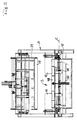
- Fig.1
- eine Seitenansicht einer erfindungsgemäßen Vorrichtung,
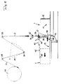
- Fig.2
- die Stirnansicht in Richtung des Pfeils II in Fig.1,
- Fig.3
- den senkrechten Schnitt III-III in Fig.1,
- Fig.4
- einen vergrößerten Ausschnitt aus Fig.1,
- Fig.5
- die Ansicht in Richtung des Pfeils V in Fig.4,
- Fig.6
- einen weiter vergrößerten Ausschnitt aus Fig.4 und
- Fig.7 bis 12
- sechs aufeinanderfolgende Zustände innerhalb eines Maschinenzyklus.
- Fig. 1
- a side view of a device according to the invention,
- Fig. 2
- the front view in the direction of arrow II in Fig.1,
- Fig. 3
- the vertical section III-III in Fig.1,
- Fig. 4
- 2 shows an enlarged section from FIG. 1,
- Fig. 5
- the view in the direction of arrow V in Figure 4,
- Fig. 6
- a further enlarged section of Fig.4 and
- Fig. 7 to 12
- six successive states within one machine cycle.
Mit der dargestellten Vorrichtung werden annähernd quaderförmige
Isolierstoffballen, im folgenden kurz Quader 1 genannt,
mit einer Bahn 2 aus Packpapier umwickelt. Im dargestellten
Beispiel ist die Höhe der Quader 1 größer als ihre Breite. Die
Bahn 2 wird jeweils zunächst an die Vorderseite 3, dann an die
Oberseite 4 und die Unterseite 5 und schließlich an die Rückseite
6 eines Quaders 1 angelegt, wobei Bahnenden an der Rückseite
6 eine Überlappung 7 bilden und dort miteinander verklebt
werden. Die Bahn 2 ist vorzugsweise um soviel breiter als die
Ober- und Unterseite 4 bzw. 5 des Quaders 1, daß seitliche Überstände
entstehen, die anschließend umgefaltet werden, um die
Längsseiten 8 des Quaders zu bedecken. Zu diesem Zweck werden
die Quader 1 in verhältnismäßig geringen Abständen voneinander
in Richtung des Pfeils 9 in Fig.1 durch die dargestellte Vorrichtung
hindurchgefördert.With the device shown are approximately cuboid
Insulation bales, hereinafter referred to as
Die Vorrichtung hat ein Gestell 10, das einen Tunnel bildet. Zu
diesem führt eine Förderstrecke 11 hin, auf der jeweils ein
Quader 1 von einem Schieber 12 in Richtung des Pfeils 9 bewegt
wird. Der Schieber 12 arbeitet intermittierend; er wird jeweils
aus seiner in Fig.1 mit gestrichelten Linien angedeuteten vorderen
Stellung in die mit vollen Linien gezeichnete Ruhestellung
zurückgezogen.The device has a
An die erste Förderstrecke 11 schließt sich eine zweite Förderstrecke
13 an, wobei zwischen diesen beiden Förderstrecken ein
in Bezug auf deren Förderrichtung (Pfeil 9) querliegender Spalt
14 freibleibt. Beiderseits der zweiten Förderstrecke 13 sind
Schranken 15 angeordnet, von denen jeweils ein Quader 1 angehalten
wird, ehe er auf der zweiten Förderstrecke 13 mitgenommen
wird.A second conveyor line connects to the
An die zweite Förderstrecke 13 schließt sich eine dritte Förderstrecke
17 an, an deren beiden Seiten Klappen 18 zum Umbiegen
der erwähnten seitlichen Überstände der Bahn 2 vorgesehen
sind. Die Klappen 18 sind auf je einem querliegenden Schlitten
19 befestigt, sodaß der Abstand zwischen einander gegenüberliegenden
Klappen 18 zur Anpassung an Quader 1 unterschiedlicher
Breite einstellbar ist.A third conveyor line connects to the
Oberhalb der zweiten Förderstrecke 13 ist eine waagerechte Andrückplatte
20 angeordnet, die mittels einer Scherenanordnung
21 am Gestell 10 aufgehängt und mittels eines Stelltriebs 22
parallel zu sich selbst verstellbar ist, um sich unterschiedlichen
Höhen der Quader 1 anzupassen.Above the
Auf dem Gestell 10 ist ein Magazin 23 mit zwei Lagerböcken 24
für je eine Papierrolle 25 angeordnet. Von jeder dieser Rollen
25 läßt sich Papier in einer Bahn 2 abziehen, wobei die Wahl
besteht, jeweils eine der Rollen 25 als Ersatzrolle bereitzuhalten
oder das Papier von beiden Rollen 25 gleichzeitig abzuziehen,
wenn eine zweilagige Bahn zum Umwickeln der Quader 1
verwendet werden soll. Es ist auch möglich, auf den beiden
Rollen 25 Bahnen 2 unterschiedlicher Breite bereitzuhalten.On the
Die Bahn 2 läuft entweder über eine Umlenkrolle 26 an einem der
Lagerböcke 24 oder direkt nach oben zu einem ersten Portal 27
über eine dort gelagerte zweite Umlenkrolle 28, durch einen
ebenfalls an diesem Portal 27 gelagerten, rahmenförmigen Tänzer
29 hindurch über eine an diesem gelagerte dritte Umlenkrolle
30. Der Tänzer 29 ist mit dem ersten Portal 27 durch einen regelbaren
Stelltrieb 31 verbunden, der es ermöglicht, in der Bahn 2
eine vorgewählte Spannung aufrechtzuerhalten. Von der dritten
Umlenkrolle 30 erstreckt sich die Bahn 2 wieder nach oben zu
einem zweiten Portal 32 und um eine dort angeordnete Umlenkung
33, die ebenfalls eine Umlenkrolle sein kann. Senkrecht unterhalb
dieser Umlenkung 33 ist eine Antriebswalze 34 angeordnet,
die zusammen mit einer zweiten Antriebswalze 35 einen Walzenspalt
bildet, durch den die Bahn 2 senkrecht nach unten hindurchgeführt
wird. Sämtliche Umlenkrollen und Antriebswalzen
haben waagerechte, in bezug auf die Förderrichtung 9 querliegende
Achsen.The
Der Walzenspalt zwischen den Antriebswalzen 34 und 35 liegt
senkrecht über dem Spalt 14 zwischen den beiden Förderstrecken
11 und 13. Unmittelbar unterhalb dieses Walzenspalts ist eine
querliegende Schiene 36 angeordnet, an der eine Klebstoffauftrage- und Trennvorrichtung 37 entlangbewegbar ist. In geringem
Abstand hinter der senkrechten Ebene, die durch die Umlenkung
33 und den Walzenspalt zwischen den Antriebswalzen 34 und 35
definiert ist, befindet sich der Arbeitsbereich eines Mitnehmers
38. Der Mitnehmer 38 ist ein waagerechtes Rohr, das
sich quer zur Förderrichtung 9, also parallel zur Umlenkung 33
und den Antriebswalzen 34 und 35 erstreckt, eine perforierte
Mantelfläche hat und intermittierend evakuierbar ist, wodurch
die Bahn 2 an den Mitnehmer 38 ansaugbar und von ihm mitnehmbar
ist.The nip is between the
Der Mitnehmer 38 bildet den unteren Rand einer kufenartig gewölbten
Bahnführung 39, die durch ein in ihrem oberen Drittel
angeordnetes Gelenk 40 mit waagerechter, in bezug auf die Förderrichtung
9 querliegender Gelenkachse A mit einem Lenker 41
verbunden ist. Dieser ist durch ein Gelenk 42 mit ebenfalls
waagerechter, in bezug auf die Förderrichtung 9 querliegender
Gelenkachse B an der Andrückplatte 20 gelagert. Der Lenker 41
ist rahmenartig gestaltet und weist etwa in seiner Mitte eine
Lagerstelle 43 auf, die durch einen Stelltrieb 44 mit einem
oberen Endbereich der Bahnführung 39, und durch einen weiteren
Stelltrieb 45 mit der Andrückplatte 20, verbunden ist. The
Unterhalb des zwischen den beiden Förderstrecken 11 und 13 gebildeten
Spalts 14 beginnt ein nach unten führender Kanal 46,
der kreisbogenförmig nach vorne, in Förderrichtung 9, gebogen
ist, sich über die gesamte Breite des Spalts 14 erstreckt und
nach vorne hin allmählich enger wird. Der Kanal 46 ist an einer
Traverse 47 angeordnet, die den Spalt 14 nach vorne hin begrenzt.
An der Traverse 47 ist eine Klappe 48 mittels eines
Gelenks 49 mit waagerechter, querliegender Achse C gelagert.
Die Klappe 48 ist mit dem Gestell 10 durch einen Stelltrieb 50
verbunden; dadurch ist sie aus einer Ruhestellung, in der sie
in der Ebene der zweiten Förderstrecke 13 liegt, in eine Andrückstellung
schwenkbar, in der sie vom Gelenk 49 senkrecht nach
oben ragt.Below that formed between the two
Die Arbeitsweise der in Fig.1 bis 6 dargestellten Vorrichtung wird nun anhand der Fig.7 bis 12 näher erläutert:The operation of the device shown in Fig.1 to 6 is now explained in more detail with reference to FIGS. 7 to 12:
In Fig.7 nehmen der Schieber 12 und der Mitnehmer 38 ihre Ruhestellung
ein. Nun setzt eine nicht dargestellte Zubringevorrichtung
üblicher Bauart einen Quader 1 vor dem Schieber 12 ab,
und der Mitnehmer 38 wird unter Vakuum gesetzt, so daß er das
Ende der Bahn 2 ansaugt. Anschließend wird der Lenker 41 von
seinem Stelltrieb 45 abwärts geschwenkt und der Stelltrieb 44
bewirkt eine geringfügige Korrekturbewegung der Bahnführung 39,
so daß der Mitnehmer 38 ungefähr senkrecht abwärts bewegt wird.
Die Bahn 2 wird von den Antriebswalzen 34 und 35 nach unten
gefördert, sodaß sie sich zusammen mit der Bahnführung 39, an
dieser anliegend, abwärts bewegt. Alternativ kann auf das Ansaugen
der Bahn 2 durch den Mitnehmer 38 verzichtet werden und
dieser kann samt Bahnführung 39 schon seine untere Stellung
gemäß Fig.8 erreicht haben, wenn die Antriebswalzen 34 und 35
beginnen, die Bahn nach unten zu fördern. In jedem Fall wird
die Bahn 2 von den Antriebswalzen 34 und 35 soweit nach unten
gefördert, daß sie durch den Spalt 14 hindurch in den Kanal 46
eintritt, während der Mitnehmer 38 wieder aufwärts in seine
Ruhestellung bewegt wird.In Figure 7, the
Wenn der in Fig.9 abgebildete Zustand erreicht ist, wird der
Schieber 12 nach links bewegt, so daß er den Quader 1 vorwärts
schiebt. Dessen Vorderseite 3 drückt infolgedessen gegen den
senkrecht herabhängenden Abschnitt der Bahn 2, wobei diese sich
zunächst an die Vorderseite 3 und dann an die Oberseite 4 sowie
gleichzeitig an die Unterseite 5 des Quader 1 anlegt, während
dieser gemäß Fig.10 über den Spalt 14 hinweggeschoben wird.
Dabei gleitet der untere Abschnitt der Bahn 2 über die waagerecht
liegende Klappe 48, die einen gewissen Reibungswiderstand
auf die Bahn ausübt. Die Antriebswalzen 34 und 35 sind während
der in Fig.10 abgebildeten Vorwärtsbewegung des Quaders 1 unwirksam;
der Tänzer 29 wirkt jedoch bremsend auf die Bahn 2. Infolgedessen
wird die Bahn 2 straff über die Oberseite 4 und
über die Unterseite 5 gezogen.When the state shown in Fig. 9 is reached, the
Sobald der Schieber 12 den Quader 1 vollständig über den Spalt
14 und zumindest im wesentlichen auch über die Klappe 48 hinweggeschoben
hat, wird die Andrückplatte 20 gemäß Fig.11 abgesenkt,
sodaß sie den Quader 1 festklemmt. Dann wird der Schieber
12 zurückgezogen und unmittelbar darauf wird die Klappe 48
nach oben geschwenkt, so daß sie das Ende der Bahn 2 an die
Rückseite 6 des Quaders 1 anlegt. Gleichzeitig wird der Mitnehmer
38 gemäß Fig.11 abwärts bewegt, ohne jedoch unter Vakuum gesetzt
zu werden. Infolgedessen gleitet der Mitnehmer 38 über
die Bahn 2 und legt sie von oben nach unten an die Rückseite 6
des Quaders 1 an, während dieser weiterhin durch die von der
Andrückplatte 20 auf ihn ausgeübte, nach unten gerichtete Kraft
festgeklemmt wird.As soon as the
Im Verlauf der Abwärtsbewegung des Mitnehmers 38 wird die Bahn
2 von der Vorrichtung 37 durchtrennt, nachdem sie unmittelbar
unterhalb der Trennstelle mit Klebstoff bestrichen oder besprüht
worden ist. Der um den Quader 1 herumgewickelte Bahnabschnitt
hat nun zwei Enden, die vom Mitnehmer 38 in eine überlappende
Lage gemäß Fig.12 gebracht und miteinander verklebt werden.
Anschließend wird die Andrückplatte 20 wieder aufwärts bewegt,
so daß sie den Quader 1 freigibt und dieser von den Bandförderern
15 längs der zweiten Förderstrecke 13 weiterbewegt wird.
Gleichzeitig werden der Mitnehmer 38 nach oben und die Klappe
48 nach unten in die Ruhestellung gemäß Fig.7 bewegt.In the course of the downward movement of the
Claims (6)
- A method of wrapping parallelepipeds (1), especially bales of insulating fabric in a web (2) of wrapping material, especially paper, whereina length of web (2) corresponding to the circumference of a parallelepiped, composed of front (3), rear (6), top (4), and bottom (5) faces, plus an overlap (7) is withdrawn from a supply,the web (2) is supended above the plane of the top face (4) of the parallelepiped (1) and forms a first web end below the plane of the bottom face (5) of the parallelepiped (1),the parallelepiped (1) is moved by its front face (3) against the suspended web (2) and is carried on approximately at right angles to latter, the web (2) making contact also with the top (4) and bottom (5) faces,a second web end still connected to the supply is brought into contact with the rear face (6) of the parallelepiped (1), starting from the top face (4) thereof, andthe web ends are superposed and interconnected,
characterized in thatthe first web end is guided slidingly and folded upwardly at the rear face (6) of the parallelepiped (1), andthe second web end, in the course of its downward movement, is severed from the supply along the rear face (6) of the parallelepiped (1) where it is connected to the upwardly folded first web end, especially by gluing. - The method as claimed in claim 1, characterized in that the parallelepiped (1) is clamped in position while the web ends are brought into contact with the rear face (6) thereof, where they are interconnected.
- An apparatus for wrapping parallelepipeds (1), especially bales of insulating fabric in a web (2) of wrapping material, especially paper, comprisingfirst and second, approximately horizontal conveying tracks (11, 13) between which a transversely extending gap (14) is left open across which the parallelepipeds can be moved,a magazine (23) in which a supply of web (2) is kept,a deflecting member (33) over which the web (2) can be withdrawn in order then to be passed approximately vertically through the gap (14), andan entraining member (38) designed to grasp the web (2) and be controlled at least biaxially so that it can be pressed against the rear face (6) of the parallelepiped, following the movement of the parallelepiped (1) across the gap (14) and subsequent to the web (2) contacting the top face (4) of the parallelepiped (1),
characterized in that a flap (48) is supported at the entry to the second conveying track (13) to form a support for the lower part of the web (2) entrained by the parallelepiped (1) during its forward movement and to be moved upwardly behind the parallelepiped (1) in order to bring the lower end of the web (2) into contact with the rear face (6) of the parallelepiped (1) at a level which can be reached by the entraining member (38) so as to make the overlap (7). - The apparatus as claimed in claim 3, characterized in that the entraining member (38) is disposed at the lower edge of a skid-like web guide (39) mounted on a guide bar (41) for pivoting movement about a horizontal axis (A) which extends parallel to the gap (14), the guide bar being pivotable about another horizontal axis (B) extending in parallel with the gap (14).
- The apparatus as claimed in any one of claims 2 to 4, characterized in that a pair of drive rollers (34, 35) are arranged above the gap (14) between which the web (2) can be passed.
- The apparatus as claimed in claim 5, characterized in that a severing means (37) for cutting off the web (2) which has been brought into contact from above with the rear face (6) of the parallelepiped (1) likewise is arranged above the gap (14) yet below the drive rollers (34, 35).
Applications Claiming Priority (2)
| Application Number | Priority Date | Filing Date | Title |
|---|---|---|---|
| DE4416540A DE4416540C1 (en) | 1994-05-10 | 1994-05-10 | Method of wrapping blocks of insulating material |
| DE4416540 | 1994-05-10 |
Publications (2)
| Publication Number | Publication Date |
|---|---|
| EP0681957A1 EP0681957A1 (en) | 1995-11-15 |
| EP0681957B1 true EP0681957B1 (en) | 1998-06-03 |
Family
ID=6517813
Family Applications (1)
| Application Number | Title | Priority Date | Filing Date |
|---|---|---|---|
| EP95104388A Expired - Lifetime EP0681957B1 (en) | 1994-05-10 | 1995-03-24 | Method and device for wrapping cubolds, especially bales of insulating material with wrapping material |
Country Status (2)
| Country | Link |
|---|---|
| EP (1) | EP0681957B1 (en) |
| DE (2) | DE4416540C1 (en) |
Families Citing this family (4)
| Publication number | Priority date | Publication date | Assignee | Title |
|---|---|---|---|---|
| DE29515605U1 (en) * | 1995-09-30 | 1995-12-14 | Colsman & Kirschner Gmbh & Co | Automatic packaging machine with automatic change of packaging material |
| IT1320919B1 (en) * | 2000-03-14 | 2003-12-10 | Resta Srl | MATTRESS PACKAGING MACHINE IN A SHEET CARRIED OUT CONTINUOUSLY ON A COIL. |
| FR2815012B3 (en) * | 2000-10-05 | 2002-09-13 | Smurfit Socar Sa | METHOD FOR COMBINING IDENTICAL PARALLELEPIPEDIC PACKAGES ON A CONTINUOUS CONVOYAFE SYSTEM |
| CN116461767B (en) * | 2023-06-05 | 2023-10-03 | 山东大宏智能设备股份有限公司 | Automatic six-sided garbage packaging equipment |
Family Cites Families (6)
| Publication number | Priority date | Publication date | Assignee | Title |
|---|---|---|---|---|
| DE1170859B (en) * | 1961-03-07 | 1964-05-21 | Hesser Ag Maschf | Device on wrapping machines for folding wrapping blanks around block-shaped objects |
| US3238697A (en) * | 1962-10-26 | 1966-03-08 | Gen Strapping Company | Bundle wrapping apparatus |
| US3372526A (en) * | 1965-01-22 | 1968-03-12 | Scandia Packaging Mach | Wrapping mechanism |
| DE1299548B (en) * | 1966-04-16 | 1969-07-17 | Bauer Eberhard | Machine for wrapping objects with plastic film |
| DE2450373A1 (en) * | 1974-10-23 | 1976-04-29 | Bauer Eberhard | MACHINE FOR COVERING ITEMS WITH PLASTIC FILM |
| FR2565201A1 (en) * | 1984-05-30 | 1985-12-06 | Ouest Conditionnement Delapier | METHOD AND INSTALLATION FOR PACKAGING A PACKET USING A PACKAGE SHEET AND PACKAGED PACKAGES OBTAINED |
-
1994
- 1994-05-10 DE DE4416540A patent/DE4416540C1/en not_active Expired - Fee Related
-
1995
- 1995-03-24 DE DE59502388T patent/DE59502388D1/en not_active Expired - Fee Related
- 1995-03-24 EP EP95104388A patent/EP0681957B1/en not_active Expired - Lifetime
Also Published As
| Publication number | Publication date |
|---|---|
| DE4416540C1 (en) | 1995-08-17 |
| EP0681957A1 (en) | 1995-11-15 |
| DE59502388D1 (en) | 1998-07-09 |
Similar Documents
| Publication | Publication Date | Title |
|---|---|---|
| EP0050860B1 (en) | Device for forming and stapling segments separated from a tubular foil web | |
| DE3143063C2 (en) | ||
| DE3723601C2 (en) | ||
| DE1561966A1 (en) | Method and device for packaging goods | |
| DE3038058A1 (en) | DEVICE FOR STACKING FLAT ITEMS, IN PARTICULAR FOLDING CARTON CUTS | |
| EP1808374B1 (en) | Film packaging machine for packaged goods of varying size | |
| DE2038959C3 (en) | Bag making machine | |
| DE2101116C3 (en) | Butt splicing device for butt-to-butt joining of webs | |
| EP0111210A1 (en) | Device for wrapping articles with a plastic sheet or the like | |
| DE3301852A1 (en) | METHOD AND DEVICE FOR THE PROCESSING OF TWO EACH PRODUCTS FORMED BY FLAT PRODUCTS, PREFERRED PRINTED PRODUCTS | |
| DE3300068A1 (en) | METHOD AND MACHINE FOR PACKING A COMPRESSIBLE STACK, ESPECIALLY PRINTING | |
| EP0681957B1 (en) | Method and device for wrapping cubolds, especially bales of insulating material with wrapping material | |
| DE3203644C2 (en) | Device for the automatic joining of film webs | |
| DE3239378A1 (en) | INTERMEDIATE PRODUCT OF A ROLL PACKING MACHINE | |
| DE4127854A1 (en) | DEVICE FOR FEEDING PLATE-SHAPED CUTS TO A DEEP-DRAWING MACHINE | |
| EP0506645B1 (en) | Apparatus for fabrication of battery plate envelopes | |
| DE2024150A1 (en) | Bow straightener | |
| WO2009121542A1 (en) | Device and method for producing bags from pieces of tubing | |
| AT412134B (en) | Process for jacketing battery plates, especially lead plates for industrial batteries, comprises placing a second layer of fiber fleece and a plastic film around the battery plate which already has a first layer of fiber fleece | |
| WO2002010021A2 (en) | Method and device for packaging a block consisting of compressible material, and a packaged block | |
| EP0114200B1 (en) | Device for joining the terminal end of a web wound onto a roll to the lead end of the web of a new roll | |
| DE19753870B4 (en) | Method and device for connecting the end of a first material web to the beginning of a second material web | |
| DE19735418A1 (en) | Method and device for feeding a wrapping material web to a tubular bag packaging machine | |
| DE1971954U (en) | DEVICE FOR PACKAGING SHEETS. | |
| DE2832391B1 (en) | Device for applying web sections to a flat workpiece |
Legal Events
| Date | Code | Title | Description |
|---|---|---|---|
| PUAI | Public reference made under article 153(3) epc to a published international application that has entered the european phase |
Free format text: ORIGINAL CODE: 0009012 |
|
| AK | Designated contracting states |
Kind code of ref document: A1 Designated state(s): DE FR GB IT SE |
|
| 17P | Request for examination filed |
Effective date: 19951205 |
|
| 17Q | First examination report despatched |
Effective date: 19970115 |
|
| GRAG | Despatch of communication of intention to grant |
Free format text: ORIGINAL CODE: EPIDOS AGRA |
|
| GRAG | Despatch of communication of intention to grant |
Free format text: ORIGINAL CODE: EPIDOS AGRA |
|
| GRAH | Despatch of communication of intention to grant a patent |
Free format text: ORIGINAL CODE: EPIDOS IGRA |
|
| GRAH | Despatch of communication of intention to grant a patent |
Free format text: ORIGINAL CODE: EPIDOS IGRA |
|
| GRAA | (expected) grant |
Free format text: ORIGINAL CODE: 0009210 |
|
| ITF | It: translation for a ep patent filed |
Owner name: BARZANO' E ZANARDO MILANO S.P.A. |
|
| AK | Designated contracting states |
Kind code of ref document: B1 Designated state(s): DE FR GB IT SE |
|
| REF | Corresponds to: |
Ref document number: 59502388 Country of ref document: DE Date of ref document: 19980709 |
|
| GBT | Gb: translation of ep patent filed (gb section 77(6)(a)/1977) |
Effective date: 19980728 |
|
| ET | Fr: translation filed | ||
| PLBE | No opposition filed within time limit |
Free format text: ORIGINAL CODE: 0009261 |
|
| STAA | Information on the status of an ep patent application or granted ep patent |
Free format text: STATUS: NO OPPOSITION FILED WITHIN TIME LIMIT |
|
| 26N | No opposition filed | ||
| PGFP | Annual fee paid to national office [announced via postgrant information from national office to epo] |
Ref country code: FR Payment date: 20010131 Year of fee payment: 7 |
|
| PGFP | Annual fee paid to national office [announced via postgrant information from national office to epo] |
Ref country code: GB Payment date: 20010201 Year of fee payment: 7 |
|
| PGFP | Annual fee paid to national office [announced via postgrant information from national office to epo] |
Ref country code: SE Payment date: 20010323 Year of fee payment: 7 Ref country code: DE Payment date: 20010323 Year of fee payment: 7 |
|
| REG | Reference to a national code |
Ref country code: GB Ref legal event code: IF02 |
|
| PG25 | Lapsed in a contracting state [announced via postgrant information from national office to epo] |
Ref country code: GB Free format text: LAPSE BECAUSE OF NON-PAYMENT OF DUE FEES Effective date: 20020324 |
|
| PG25 | Lapsed in a contracting state [announced via postgrant information from national office to epo] |
Ref country code: SE Free format text: LAPSE BECAUSE OF NON-PAYMENT OF DUE FEES Effective date: 20020325 |
|
| PG25 | Lapsed in a contracting state [announced via postgrant information from national office to epo] |
Ref country code: DE Free format text: LAPSE BECAUSE OF NON-PAYMENT OF DUE FEES Effective date: 20021001 |
|
| EUG | Se: european patent has lapsed |
Ref document number: 95104388.4 |
|
| GBPC | Gb: european patent ceased through non-payment of renewal fee |
Effective date: 20020324 |
|
| PG25 | Lapsed in a contracting state [announced via postgrant information from national office to epo] |
Ref country code: FR Free format text: LAPSE BECAUSE OF NON-PAYMENT OF DUE FEES Effective date: 20021129 |
|
| REG | Reference to a national code |
Ref country code: FR Ref legal event code: ST |
|
| PG25 | Lapsed in a contracting state [announced via postgrant information from national office to epo] |
Ref country code: IT Free format text: LAPSE BECAUSE OF NON-PAYMENT OF DUE FEES;WARNING: LAPSES OF ITALIAN PATENTS WITH EFFECTIVE DATE BEFORE 2007 MAY HAVE OCCURRED AT ANY TIME BEFORE 2007. THE CORRECT EFFECTIVE DATE MAY BE DIFFERENT FROM THE ONE RECORDED. Effective date: 20050324 |