EP0528530A1 - GPS-Navigationssystem mit selektivem Updating - Google Patents
GPS-Navigationssystem mit selektivem Updating Download PDFInfo
- Publication number
- EP0528530A1 EP0528530A1 EP92306327A EP92306327A EP0528530A1 EP 0528530 A1 EP0528530 A1 EP 0528530A1 EP 92306327 A EP92306327 A EP 92306327A EP 92306327 A EP92306327 A EP 92306327A EP 0528530 A1 EP0528530 A1 EP 0528530A1
- Authority
- EP
- European Patent Office
- Prior art keywords
- current position
- movable body
- data
- navigation system
- position measurement
- Prior art date
- Legal status (The legal status is an assumption and is not a legal conclusion. Google has not performed a legal analysis and makes no representation as to the accuracy of the status listed.)
- Withdrawn
Links
Images

Classifications
-
- G—PHYSICS
- G01—MEASURING; TESTING
- G01C—MEASURING DISTANCES, LEVELS OR BEARINGS; SURVEYING; NAVIGATION; GYROSCOPIC INSTRUMENTS; PHOTOGRAMMETRY OR VIDEOGRAMMETRY
- G01C21/00—Navigation; Navigational instruments not provided for in groups G01C1/00 - G01C19/00
- G01C21/26—Navigation; Navigational instruments not provided for in groups G01C1/00 - G01C19/00 specially adapted for navigation in a road network
- G01C21/28—Navigation; Navigational instruments not provided for in groups G01C1/00 - G01C19/00 specially adapted for navigation in a road network with correlation of data from several navigational instruments
-
- G—PHYSICS
- G01—MEASURING; TESTING
- G01S—RADIO DIRECTION-FINDING; RADIO NAVIGATION; DETERMINING DISTANCE OR VELOCITY BY USE OF RADIO WAVES; LOCATING OR PRESENCE-DETECTING BY USE OF THE REFLECTION OR RERADIATION OF RADIO WAVES; ANALOGOUS ARRANGEMENTS USING OTHER WAVES
- G01S19/00—Satellite radio beacon positioning systems; Determining position, velocity or attitude using signals transmitted by such systems
- G01S19/38—Determining a navigation solution using signals transmitted by a satellite radio beacon positioning system
- G01S19/39—Determining a navigation solution using signals transmitted by a satellite radio beacon positioning system the satellite radio beacon positioning system transmitting time-stamped messages, e.g. GPS [Global Positioning System], GLONASS [Global Orbiting Navigation Satellite System] or GALILEO
- G01S19/42—Determining position
- G01S19/48—Determining position by combining or switching between position solutions derived from the satellite radio beacon positioning system and position solutions derived from a further system
- G01S19/49—Determining position by combining or switching between position solutions derived from the satellite radio beacon positioning system and position solutions derived from a further system whereby the further system is an inertial position system, e.g. loosely-coupled
Definitions
- the present invention generally relates to navigation systems, and more particularly to a navigation system using a GPS (Global Positioning system) receiver. More specifically, the present invention is concerned with a technique intended to preventing fluctuations in data indicating the current position of a movable body maintained in the stationary state.
- GPS Global Positioning system
- a GPS navigation system utilizing artificial satellites is one kind of navigation system for use in movable bodies, such as automobiles, airplanes and ships.
- a GPS receiver used in such a GPS navigation system receives electric waves for position measurement, which are transmitted by three or more GPS satellite.
- the GPS receiver is adapted to measure the position of the electric wave receiving point by using pseudo-distance data including time offsets between the receiving point and each of the GPS satellites and pieces of data indicating each position of the GPS satellite.
- the receiver outputs GPS position measurement data indicating the position of the receiving point.
- the GPS position measurement data includes an error due to various factors, and hence the data indicating the current position of the receiving point also includes an error (approximately is a range of ⁇ 30m in general).
- the current position data including such an error since the quantity of error obtained at each position measurement timing varies, the current position changes even when the movable body is maintained in the stationary state.
- the current position of the movable body measured in the above manner is indicated on a m ap displayed on a display device in such a manner that the map is kept stationary, the current position varies on the map nevertheless the movable body is in fact maintained in the stationary state.
- a display of the map fluctuates.
- a position measurement receiver receives an electric wave for use in position measurement transmitted from a satellite and generates current position data on the basis of the received electric wave at each predetermined position measurement timing, the current position data indicating the current position of a movable body in which the navigation system is installed.
- a storage unit which is coupled to the position measurement receiver, stores latest current position data generated by the position measurement receiver in lieu of previous current position data so that the current position data stored in the storage unit is updated at the predetermined position measurement timing.
- a speed detection sensor outputs speed data indicating a speed of movement of the movable body.
- An update inhibiting unit which is coupled to the storage unit and the speed detection sensor, determines whether or not the movable body is maintained in a stationary state on the basis of the speed data, and inhibits the storage unit to update the current position data when it determines that the movable body is maintained in the stationary state.
- the updated current position data can be prevented from being fluctuated regardless of the error caused in the GPS signal detecting operation etc., according to the present invention.
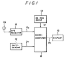
- FIG. 1 shows the basic structure of an on-vehicle navigation system according to an embodiment of the present invention.
- An on-vehicle navigation system shown in FIG. 1 includes a GPS receiver 11, a vehicle speed sensor 12, a CD-ROM drive 13, a microcomputer 14 and a display 15.
- the GPS receiver 11 receives an electric wave from a GPS satellite (not shown) through an antenna 11A, and generates GPS position measurement data D G from the received electric wave.
- the vehicle speed sensor 12 counts vehicle speed pulses dependent on revolutions of a wheel shaft or the like, and generates data D V indicating the current vehicle speed.
- the microcomputer 14 reads map data M from the a CD-ROM drive 13 on the basis of the inputted data D G , executes map-matching the data D G with the map data M, and generates display data D D for displaying the current position of the vehicle on the map.
- the display 15 displays the current position of the vehicle on the map by using the display data D D supplied from the microcomputer 14.
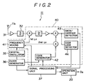
- the GPS receiver 11 will be described in detail with reference to FIG. 2.
- the antenna 11A is coupled to a GPS receiving unit 40 via a preamplifier 31 and a band-pass filter 32.
- the GPS receiver 11 is provided with an operation unit 20, a crystal oscillator 35, a clock generator 36, and a signal processing unit 37.
- a frequency mixing circuit 41 generates a signal having the same pattern as data relating to a carrier of the GPS satellite, the position thereof, and a clock built in the GPS satellite.
- the crystal oscillator 35 generates a reference frequency signal, which is a reference timing control signal of the GPS receiver 11.
- the clock generator 36 generates, from the reference frequency signal, a clock signal for controlling operation timings of the signal processing unit 37.
- the operation unit 20 is connected to the signal processing unit 37 so as to generate the GPS data D G on the basis of the output of the signal processing unit 37.
- a code generator 42 receives the clock signal generated by the clock generator 36, and generates a code signal having the same pattern as a distance measurement signal from the GPS satellite on the basis of the clock signal.
- a data/carrier detector 43 synchronously or mutually detects, by using the output signals of the frequency mixing circuit 41 and the code generator 42, data relating to the clock built in the GPS satellite and an orbit of the GPS satellite, and the carrier.
- a code lock detector 44 synchronously detects the above-mentioned distance measurement signal by using the code signal generated by the code generator 42.
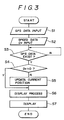
- the GPS position measurement data D G outputted from the GPS receiver 11 is applied to the microcomputer 14 as shown in FIG. 1 at each predetermined position measurement timing (step S1).
- the vehicle speed data D V outputted from the vehicle speed sensor 12 is also applied to the microcomputer 14 at each predetermined position measurement timing (step S2).
- the microcomputer 14 determines whether or not the GPS position measurement data D G is received (step S3). When it is determined that the GPS position measurement data D G is not yet received (NO), the microcomputer 14 executes step S3 again.
- step S3 When it is determined, in step S3, that the GPS position measurement data D G has been received (YES), the flow branches to the step S4.
- the microcomputer 14 determines, by referring to the vehicle speed data D V , whether or not the vehicle is maintained in the stationary state (step S4). More specifically, in step S4, the microcomputer 14 determines whether or not the vehicle speed data D V indicates zero or a value nearly equal thereto.
- step S4 When it is determined, in step S4, that the vehicle is maintained in the stationary state (YES), that is, when the vehicle speed data D V indicates zero or a value nearly equal thereto, the microcomputer 14 does not update the current position of the vehicle with new GPS position measurement data D G. That is, the microcomputer 14 executes the map matching with the map data M by using the previous GPS position measurement data D G , and outputs the display data D D to the display 15 (step S6). Hence, the current position of the vehicle is indicated on the map displayed on the display 15 without changing or fluctuating the current position displayed thereon (step S7).
- step S4 When the vehicle is moving (NO) in step S4, that is, when the vehicle speed data D V is equal to neither zero nor a value nearly equal thereto, the microcomputer 14 updates i.e, replaces the new GPS position measurement data D G with the GPS position measurement data D G stored in a built-in memory (not shown) (step S5). Then, the microcomputer 14 executes the map matching with the map data M by using the updated GPS position measurement data D G , and outputs the updated display data D D (step S6). Hence, the current position of the vehicle based on the movement thereof is indicated on the map on the display 15 (step S7).
- FIG. 4 A description will now be given, with reference to FIG. 4, of another embodiment of the present invention.
- it is determined whether or not the vehicle is maintained in the stationary state by determing whether or not the vehicle pulse is detected by the speed sensor 12 in FIG. 1 within a predetermined period.
- it is determined whether or not the vehicle is maintained in the stationary state by determining whether or not the vehicle speed detected by the speed sensor 12 in FIG. 1, is equal to zero or nearly equal thereto.
- the GPS position measurement data D G outputted from the GPS receiver 11 is applied to the microcomputer 14 at each predetermined position measurement timing (step S1), Subsequently, the vehicle pulse outputted from the vehicle speed sensor 12 is applied to the microcomputer 14 at each predetermined position measurement timing (step S2a).
- the microcomputer 14 determines whether or not the GPS position measurement data D G has been received (step S3). When the result of this determination is NO, the microcomputer 14 executes step S3 again.
- step S3 the microcomputer 14 detects the presence/non-presence of the speed pulse from the vehicle speed sensor 12, and determines whether or not the vehicle is maintained in the stationary state (step S4a). More specifically, the microcomputer 14 determines whether or not the speed pulse is received within a predetermined period.
- step S4a When it is determined that the vehicle is maintained in the stationary state (NO) in step S4a, that is, when the speed pulse is not detected within the predetermined period, the microcomputer 14 does not update the current position of the vehicle by means of new GPS position measurement data D G . That is, the microcomputer 14 executes the map matching with the map data M by using the previous GPS position measurement data D G , and outputs the display data D D to the display 15 (step S6). Hence, the current position of the vehicle is indicated on the map displayed on the display 15 without changing the current position displayed thereon (step S7).
- step S4a When the vehicle is moving, that is, the speed pulse is detected (YES) in step S4a, the microcomputer 14 updates i.e. substitutes the new GPS position measurement data D G for the GPS position measurement data D G currently stored in the built-in memory (step S5), Then, the microcomputer 14 executes the map matching with the map data M by using the updated GPS position measurement data D G , and outputs the updated display data D D (step S6). Hence, the current position of the vehicle based on the movement thereof is indicated on the map on the display 15 (step S7).
- the current position of the movable body is indicated on the display.
- the present invention is not limited to these embodiments, but includes a structure in which the current position is indicated by numeral data or the like, or processed for a subsequent operation.
- the numeral data etc. indicating the present position can be prevented from fluctuating, so that the treatment or process of thus stable data can be easily performed.
- the current position data generated by the present embodiments accurately indicates the current position of the movable body which is maintained in the stationary state, and hence the aforementioned disadvantages are eliminated.
Landscapes
- Engineering & Computer Science (AREA)
- Radar, Positioning & Navigation (AREA)
- Remote Sensing (AREA)
- Physics & Mathematics (AREA)
- General Physics & Mathematics (AREA)
- Computer Networks & Wireless Communication (AREA)
- Automation & Control Theory (AREA)
- Navigation (AREA)
- Position Fixing By Use Of Radio Waves (AREA)
Applications Claiming Priority (2)
| Application Number | Priority Date | Filing Date | Title |
|---|---|---|---|
| JP3182296A JPH0526680A (ja) | 1991-07-23 | 1991-07-23 | Gpsナビゲーシヨン装置 |
| JP182296/91 | 1991-07-23 |
Publications (1)
| Publication Number | Publication Date |
|---|---|
| EP0528530A1 true EP0528530A1 (de) | 1993-02-24 |
Family
ID=16115807
Family Applications (1)
| Application Number | Title | Priority Date | Filing Date |
|---|---|---|---|
| EP92306327A Withdrawn EP0528530A1 (de) | 1991-07-23 | 1992-07-09 | GPS-Navigationssystem mit selektivem Updating |
Country Status (2)
| Country | Link |
|---|---|
| EP (1) | EP0528530A1 (de) |
| JP (1) | JPH0526680A (de) |
Cited By (8)
| Publication number | Priority date | Publication date | Assignee | Title |
|---|---|---|---|---|
| WO1994027265A1 (en) * | 1993-05-06 | 1994-11-24 | Spectronics Micro Systems Limited | Improvements in automatic vehicle location systems |
| DE19638515A1 (de) * | 1996-09-20 | 1998-04-02 | Grundig Ag | Verfahren und Vorrichtung zur Zuordnung von Nachrichten, insbesondere Verkehrsnachrichten |
| US5914675A (en) * | 1996-05-23 | 1999-06-22 | Sun Microsystems, Inc. | Emergency locator device transmitting location data by wireless telephone communications |
| WO2002021478A2 (en) * | 2000-09-07 | 2002-03-14 | Ericsson Inc. | Method to control the update frequency of a positioning device by a mobile terminal |
| US7027488B2 (en) | 2000-11-04 | 2006-04-11 | Koninklijke Philips Electronics N.V. | Spread spectrum receiver and related method |
| US8142304B2 (en) | 2000-12-19 | 2012-03-27 | Appalachian Technology, Llc | Golf round data system golf club telemetry |
| US8172702B2 (en) | 2000-06-16 | 2012-05-08 | Skyhawke Technologies, Llc. | Personal golfing assistant and method and system for graphically displaying golf related information and for collection, processing and distribution of golf related data |
| US8221269B2 (en) | 2000-06-16 | 2012-07-17 | Skyhawke Technologies, Llc | Personal golfing assistant and method and system for graphically displaying golf related information and for collection, processing and distribution of golf related data |
Families Citing this family (6)
| Publication number | Priority date | Publication date | Assignee | Title |
|---|---|---|---|---|
| JP3533745B2 (ja) * | 1995-03-30 | 2004-05-31 | アイシン精機株式会社 | 移動体測位装置 |
| JP4646720B2 (ja) * | 2005-07-19 | 2011-03-09 | アルパイン株式会社 | ナビゲーション装置 |
| EP1980822A4 (de) * | 2006-02-03 | 2013-06-19 | Pioneer Corp | Navigationsvorrichtung und verfahren, programm und aufzeichnungsmedium dafür |
| KR20100028356A (ko) | 2008-09-04 | 2010-03-12 | 한국과학기술연구원 | 전이금속 산화물/다층벽 탄소나노튜브 나노복합체 및 이의 제조방법 |
| KR101109124B1 (ko) | 2009-02-12 | 2012-02-16 | 한국과학기술연구원 | 박테리아 및 전이금속 산화물로 이루어진 유ㆍ무기 복합체 및 이의 제조방법 |
| JP5138723B2 (ja) * | 2010-04-15 | 2013-02-06 | 株式会社エヌ・ティ・ティ・ドコモ | 移動端末および移動端末の制御方法 |
Citations (3)
| Publication number | Priority date | Publication date | Assignee | Title |
|---|---|---|---|---|
| GB2126040A (en) * | 1982-07-23 | 1984-03-14 | Teldix Gmbh | Navigation apparatus for land vehicles |
| US4837700A (en) * | 1987-10-27 | 1989-06-06 | Pioneer Electronic Corporation | Method and apparatus for processing data in a GPS receiving device in a road vehicle |
| US4912645A (en) * | 1987-03-26 | 1990-03-27 | Mazda Motor Corporation | Automotive navigation system |
-
1991
- 1991-07-23 JP JP3182296A patent/JPH0526680A/ja active Pending
-
1992
- 1992-07-09 EP EP92306327A patent/EP0528530A1/de not_active Withdrawn
Patent Citations (3)
| Publication number | Priority date | Publication date | Assignee | Title |
|---|---|---|---|---|
| GB2126040A (en) * | 1982-07-23 | 1984-03-14 | Teldix Gmbh | Navigation apparatus for land vehicles |
| US4912645A (en) * | 1987-03-26 | 1990-03-27 | Mazda Motor Corporation | Automotive navigation system |
| US4837700A (en) * | 1987-10-27 | 1989-06-06 | Pioneer Electronic Corporation | Method and apparatus for processing data in a GPS receiving device in a road vehicle |
Cited By (20)
| Publication number | Priority date | Publication date | Assignee | Title |
|---|---|---|---|---|
| AU689106B2 (en) * | 1993-05-06 | 1998-03-26 | Digital Dispatch Systems, Inc. | Improvements in automatic vehicle location systems |
| US5754125A (en) * | 1993-05-06 | 1998-05-19 | Mdsi Mobile Data Solutions (Uk) Ltd. | Automatic vehicle location systems |
| WO1994027265A1 (en) * | 1993-05-06 | 1994-11-24 | Spectronics Micro Systems Limited | Improvements in automatic vehicle location systems |
| US5914675A (en) * | 1996-05-23 | 1999-06-22 | Sun Microsystems, Inc. | Emergency locator device transmitting location data by wireless telephone communications |
| DE19638515A1 (de) * | 1996-09-20 | 1998-04-02 | Grundig Ag | Verfahren und Vorrichtung zur Zuordnung von Nachrichten, insbesondere Verkehrsnachrichten |
| DE19638515B4 (de) * | 1996-09-20 | 2004-01-15 | Grundig Car Intermedia System Gmbh | Verfahren und Vorrichtung zur Zuordnung von Nachrichten, insbesondere Verkehrsnachrichten |
| US8172702B2 (en) | 2000-06-16 | 2012-05-08 | Skyhawke Technologies, Llc. | Personal golfing assistant and method and system for graphically displaying golf related information and for collection, processing and distribution of golf related data |
| US9656134B2 (en) | 2000-06-16 | 2017-05-23 | Skyhawke Technologies, Llc. | Personal golfing assistant and method and system for graphically displaying golf related information and for collection, processing and distribution of golf related data |
| US8556752B2 (en) | 2000-06-16 | 2013-10-15 | Skyhawke Technologies, Llc. | Personal golfing assistant and method and system for graphically displaying golf related information and for collection, processing and distribution of golf related data |
| US8523711B2 (en) | 2000-06-16 | 2013-09-03 | Skyhawke Technologies, Llc. | Personal golfing assistant and method and system for graphically displaying golf related information and for collection, processing and distribution of golf related data |
| US8221269B2 (en) | 2000-06-16 | 2012-07-17 | Skyhawke Technologies, Llc | Personal golfing assistant and method and system for graphically displaying golf related information and for collection, processing and distribution of golf related data |
| US7209753B2 (en) | 2000-09-07 | 2007-04-24 | Ericsson Inc. | Method to control the update frequency of a positioning device by a mobile terminal |
| US6856807B1 (en) | 2000-09-07 | 2005-02-15 | Ericsson Inc. | Method to control the update frequency of a positioning device by a mobile terminal |
| WO2002021478A3 (en) * | 2000-09-07 | 2002-10-03 | Ericsson Inc | Method to control the update frequency of a positioning device by a mobile terminal |
| WO2002021478A2 (en) * | 2000-09-07 | 2002-03-14 | Ericsson Inc. | Method to control the update frequency of a positioning device by a mobile terminal |
| US7027488B2 (en) | 2000-11-04 | 2006-04-11 | Koninklijke Philips Electronics N.V. | Spread spectrum receiver and related method |
| US8142304B2 (en) | 2000-12-19 | 2012-03-27 | Appalachian Technology, Llc | Golf round data system golf club telemetry |
| US8535170B2 (en) | 2000-12-19 | 2013-09-17 | Appalachian Technology, Llc | Device and method for displaying golf shot data |
| US8758170B2 (en) | 2000-12-19 | 2014-06-24 | Appalachian Technology, Llc | Device and method for displaying golf shot data |
| US9656147B2 (en) | 2000-12-19 | 2017-05-23 | Appalachian Technology, Llc | Golf player aid with stroke result forecasting |
Also Published As
| Publication number | Publication date |
|---|---|
| JPH0526680A (ja) | 1993-02-02 |
Similar Documents
| Publication | Publication Date | Title |
|---|---|---|
| EP0527558B1 (de) | GPS-Navigationssystem mit lokaler Geschwindigkeits- und Richtungserfassung und mit PDOP-Genauigkeitsbewertung | |
| US5272483A (en) | Navigation system | |
| US5293318A (en) | Navigation system | |
| US5483456A (en) | Navigation system and a method of calculating GPS measuring deviation | |
| US5210540A (en) | Global positioning system | |
| EP0716289B1 (de) | Navigationssystem welches Koppelnavigation kombiniert mit Funkortung | |
| EP0528530A1 (de) | GPS-Navigationssystem mit selektivem Updating | |
| EP0453726A2 (de) | Gerät für Navigation eines Fahrzeuges | |
| US5434574A (en) | System for detecting an altitude of a vehicle dependent on a global positioning system | |
| EP0875731B1 (de) | Navigationsvorrichtung | |
| US6829525B2 (en) | Movement condition computing device, method, and program, and recording medium recording said program, and navigation device | |
| JP3278911B2 (ja) | 車両用gps航法装置 | |
| JP2981025B2 (ja) | Gpsデータのフィルタリング処理装置 | |
| JPH0613977B2 (ja) | 車両用走行誘導装置 | |
| JP3126751B2 (ja) | 距離補正係数の自動補正装置 | |
| JP2577160B2 (ja) | 車両位置検出装置 | |
| JPH0526678A (ja) | Gpsナビゲーシヨン装置 | |
| EP0601712A1 (de) | Navigationssystem | |
| JP3076088B2 (ja) | 距離補正係数の自動補正装置 | |
| JP3545798B2 (ja) | 現在位置算出装置 | |
| KR100542714B1 (ko) | 3축 지자기 센서를 이용한 고가도로/지하도로 판별장치 및 그제어방법 | |
| JP3197579B2 (ja) | Gpsナビゲーション装置 | |
| JP3584543B2 (ja) | ナビゲーション装置 | |
| JP3263437B2 (ja) | 車両用ナビゲーション装置 | |
| JPH06109827A (ja) | 位置検出装置 |
Legal Events
| Date | Code | Title | Description |
|---|---|---|---|
| PUAI | Public reference made under article 153(3) epc to a published international application that has entered the european phase |
Free format text: ORIGINAL CODE: 0009012 |
|
| AK | Designated contracting states |
Kind code of ref document: A1 Designated state(s): DE FR GB |
|
| 17P | Request for examination filed |
Effective date: 19930723 |
|
| STAA | Information on the status of an ep patent application or granted ep patent |
Free format text: STATUS: THE APPLICATION HAS BEEN WITHDRAWN |
|
| 18W | Application withdrawn |
Withdrawal date: 19940131 |