EP0527445A2 - Empfangsgerät für ein bewegliches Objekt - Google Patents
Empfangsgerät für ein bewegliches Objekt Download PDFInfo
- Publication number
- EP0527445A2 EP0527445A2 EP92113483A EP92113483A EP0527445A2 EP 0527445 A2 EP0527445 A2 EP 0527445A2 EP 92113483 A EP92113483 A EP 92113483A EP 92113483 A EP92113483 A EP 92113483A EP 0527445 A2 EP0527445 A2 EP 0527445A2
- Authority
- EP
- European Patent Office
- Prior art keywords
- mobile object
- receiving apparatus
- teletext
- signal
- antennas
- Prior art date
- Legal status (The legal status is an assumption and is not a legal conclusion. Google has not performed a legal analysis and makes no representation as to the accuracy of the status listed.)
- Withdrawn
Links
Images
Classifications
-
- H—ELECTRICITY
- H04—ELECTRIC COMMUNICATION TECHNIQUE
- H04N—PICTORIAL COMMUNICATION, e.g. TELEVISION
- H04N7/00—Television systems
- H04N7/08—Systems for the simultaneous or sequential transmission of more than one television signal, e.g. additional information signals, the signals occupying wholly or partially the same frequency band, e.g. by time division
- H04N7/087—Systems for the simultaneous or sequential transmission of more than one television signal, e.g. additional information signals, the signals occupying wholly or partially the same frequency band, e.g. by time division with signal insertion during the vertical blanking interval only
- H04N7/088—Systems for the simultaneous or sequential transmission of more than one television signal, e.g. additional information signals, the signals occupying wholly or partially the same frequency band, e.g. by time division with signal insertion during the vertical blanking interval only the inserted signal being digital
- H04N7/0882—Systems for the simultaneous or sequential transmission of more than one television signal, e.g. additional information signals, the signals occupying wholly or partially the same frequency band, e.g. by time division with signal insertion during the vertical blanking interval only the inserted signal being digital for the transmission of character code signals, e.g. for teletext
-
- H—ELECTRICITY
- H04—ELECTRIC COMMUNICATION TECHNIQUE
- H04B—TRANSMISSION
- H04B7/00—Radio transmission systems, i.e. using radiation field
- H04B7/02—Diversity systems; Multi-antenna system, i.e. transmission or reception using multiple antennas
- H04B7/04—Diversity systems; Multi-antenna system, i.e. transmission or reception using multiple antennas using two or more spaced independent antennas
- H04B7/08—Diversity systems; Multi-antenna system, i.e. transmission or reception using multiple antennas using two or more spaced independent antennas at the receiving station
- H04B7/0802—Diversity systems; Multi-antenna system, i.e. transmission or reception using multiple antennas using two or more spaced independent antennas at the receiving station using antenna selection
- H04B7/0817—Diversity systems; Multi-antenna system, i.e. transmission or reception using multiple antennas using two or more spaced independent antennas at the receiving station using antenna selection with multiple receivers and antenna path selection
- H04B7/082—Diversity systems; Multi-antenna system, i.e. transmission or reception using multiple antennas using two or more spaced independent antennas at the receiving station using antenna selection with multiple receivers and antenna path selection selecting best antenna path
Definitions
- the present invention relates to a receiving apparatus for a mobile object, in particular, relates to a receiving apparatus for a mobile object suitable for receiving a teletext program.
- the transmitting section multiplexes to a horizontal scanning line in a vertical blanking interval of a TV signal a text signal constructed of text data, a synchronous code, an error correction code, and so forth so as to form a multiplexed teletext signal. Thereafter, the multiplexed teletext signal is output.
- the receiving section demultiplexes the teletext signal from the TV signal, decodes into the teletext data, and outputs the teletext data on a TV set.
- the direction of directivity of the antenna should be fixed.
- the direction of directivity of the antenna varies time by time.
- the receiving apparatus for mobile objects could not receive multiplexed teletext signals. That is, the conventional apparatuses could not almost receive teletext broadcasting programs.
- an object of the present invention is to provide a receiving apparatus for a mobile object suitable for receiving a multiplexed teletext signal of a teletext broadcasting program in a good condition regardless of whether the direction of directivity of the antenna varies.
- the present invention comprises a means for detecting and selecting a most suitable signal from a plurality of channels which are composed of plurality of antennas and a plurality of decoders which correspond to the plurality of antennas.
- TV signals are received from the antennas.
- the decoders separate teletext signals from the TV signals.
- Teletext data is decoded from the teletext signals.
- the same multiplexed teletext signals are received from a plurality of channels and thereby the same teletext data are obtained on the plurality of channels.
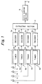
- Figure 1 is a block diagram showing a receiving apparatus for a mobile object.
- antennas 1a, 1b, 1c, and 1d are disposed on a mobile object in such a way that they can receive TV broadcasting radio waves from any directions.
- a TV signal received from the antenna 1a is sent to a tuner 2a.
- TV signals received from other antennas 1b, 1c, and 1d are also sent to tuners 2b, 2c, and 2d, respectively.
- the TV signal received from the antenna 1b is sent to the tuner 2b; the TV signal received from the antenna 1c is sent to the tuner 2c; and the TV signal received from the antenna 1d is sent to the tuner 2d.
- the tuners 2a, 2b, 2c, and 2d have a ghost canceling function. That is, the tuners 2a, 2b, 2c, and 2d selectively extract particular TV signals of the same program from the TV signals received from the antennas 1a, 1b, 1c, and 1d.
- the TV signals extracted by the tuners 2a, 2b, 2c, and 2d are sent to decoders 3a, 3b, 3c, and 3d, respectively.
- the four tuners 2a, 2b, 2c, and 2d are used.
- the number of tuners is not limited to four. In other words, one tuner can be used instead of four tuners.
- the decoders 3a, 3b, 3c, and 3d separate teletext signals from the TV signals supplied from the tuners 2a, 2b, 2c, and 2d, respectively.
- the decoders 3a, 3b, 3c, and 3d convert the teletext signals into the teletext data.
- the decoders 3a, 3b, 3c, and 3d detect and correct errors by using error correction code referred to as BEST system.
- BEST system it is known that an error of 11 bits per data packet (every 272 bits) can be corrected.
- the BEST system can recognize disability of error correction of data packets.
- the system can represent the disability of error correction for a data packet whose error cannot be corrected by setting for example an error correction disable flag.
- Teletext data which were decoded and error-corrected by the decoders 3a, 3b, 3c, and 3d are sent to an extracting section 4 through respective buffer memories.
- a channel 8a is constructed of the antenna 1a, the tuner 2a, and the decoder 3a.
- a channel 8b is constructed of the antenna 1b, the tuner 2b, and the decoder 3b.
- a channel 8c is constructed of the antenna 1c, the tuner 2c, and the decoder 3c.
- a channel 8d is constructed of the antenna 1d, the tuner 2d, and the decoder 3d.
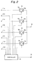
- Figure 2 is a block diagram showing the construction of the extracting section.
- a data packet which is received from the decoder 3a through a terminal 11a is sent to a terminal 14a of a switch 14.
- an error correction disable flag is sent from the decoder 3a to a controller 13 through a terminal 12a.
- a data packet which is received from the decoder 3b through a terminal 11b is sent to a terminal 15a of a switch 15.
- an error correction disable flag is sent from the decoder 3h to the controller 13 through a terminal 12b.
- a data packet which is received from the decoder 3c through a terminal 11c is sent to a terminal 16a of a switch 16.
- an error correction disable flag is sent from the decoder 3c to the controller 13 through a terminal 12c.
- a data packet which is received from the decoder 3d through a terminal lid is sent to a terminal 17a of a switch 17.
- an error correction disable flag is sent from the decoder 3d to the controller 13 through a terminal 12d.
- the controller 13 periodically determines whether the error correction disable flags have been set in accordance with the outputs of the decoders 3a, 3b, 3c, and 3d in each horizontal scanning interval. In the case that any error correction disable flag has been set, the controller 13 individually disconnects the switch 14, 15, 16, or 17 corresponding to the decoder 3a, 3b, 3c, or 3d which has output the error correction disable flag.
- the controller 13 when the controller 13 has detected a correct data packet from one of the channels 8a, 8b, 8c, and 8d, the controller 13 controls the connection states of the switches 14, 15, 16, and 17 in such a way that only the correct data packet is selected.
- a correct data packet where the error correction disable flag has not been set is output from the switch which has been selected under the control of the controller 13 from the switches 14, 15, 16, and 17 to a terminal 18.
- the data packet is sent to the data buffer section 5 and then stored therein.
- the extracting section 4 extracts a correct data packet where the error correction disable flag has not been set on the channels 8a, 8b, 8c, and 8d.
- the correct data packet is output at each horizontal scanning interval.
- a data packet or text data representing reception disability and/or control signal is stored in the data buffer section 5 at each horizontal scanning interval and extracted from the terminal 6.
- the text data of the data packet or the particular text data representing the reception disability is displayed on a display (not shown in the figure).
- Table 1 lists the results of measurement of reception ratios during traveling of an automobile as a mobile object. In this measurement, the receiving apparatus as shown in Figure 1 was used.
- the antenna has four directivities.
- Table 1 represents that the average reception ratio for discrete mode was 41 %, while that for multiplex mode was 74 %.
- the controller 13 since the controller 13 selects a correct data packet where the error correction disability flag has not been set from data packets obtained on the four channels 8a, 8b, 8c, and 8d, even if the directions of directivity of the antennas 1a, 1b, 1c, and 1d on a mobile object such as an automobile and a train vary time by time, the receiving apparatus of the present invention can correctly receive a teletext broadcasting program (multiplexed teletext signal) in a good condition.
- the receiving apparatus of the present invention can receive a teletext broadcasting program (multiplexed teletext signal) with a high sensitivity and has a resistance to loosing of data.
- the receiving apparatus since correct and most suitable text data is selected from the same text data obtained on a plurality of channels, in the case that the apparatus is used in a mobile object such as an automobile and a train, even if the direction of directivity of antennas vary time by time, the receiving apparatus can receive a teletext broadcasting program (multiplexed teletext signal) in a good condition.
- a teletext broadcasting program multiplexed teletext signal
- the apparatus of the present invention can receive a teletext broadcasting program (multiplexed teletext signal) with a high sensibility and has a resistance to loosing of data.
Landscapes
- Engineering & Computer Science (AREA)
- Signal Processing (AREA)
- Computer Networks & Wireless Communication (AREA)
- Multimedia (AREA)
- Radio Transmission System (AREA)
- Television Systems (AREA)
Applications Claiming Priority (2)
| Application Number | Priority Date | Filing Date | Title |
|---|---|---|---|
| JP3225017A JPH0549015A (ja) | 1991-08-09 | 1991-08-09 | 移動体用受信装置 |
| JP225017/91 | 1991-08-09 |
Publications (2)
| Publication Number | Publication Date |
|---|---|
| EP0527445A2 true EP0527445A2 (de) | 1993-02-17 |
| EP0527445A3 EP0527445A3 (en) | 1993-12-15 |
Family
ID=16822769
Family Applications (1)
| Application Number | Title | Priority Date | Filing Date |
|---|---|---|---|
| EP19920113483 Withdrawn EP0527445A3 (en) | 1991-08-09 | 1992-08-07 | Receiving apparatus for mobile object |
Country Status (2)
| Country | Link |
|---|---|
| EP (1) | EP0527445A3 (de) |
| JP (1) | JPH0549015A (de) |
Cited By (1)
| Publication number | Priority date | Publication date | Assignee | Title |
|---|---|---|---|---|
| EP1126632A1 (de) * | 2000-02-16 | 2001-08-22 | BECKER GmbH | Empfangseinrichtung |
Families Citing this family (1)
| Publication number | Priority date | Publication date | Assignee | Title |
|---|---|---|---|---|
| JPH10210585A (ja) * | 1997-01-20 | 1998-08-07 | Sony Corp | ヘッドホン |
Family Cites Families (2)
| Publication number | Priority date | Publication date | Assignee | Title |
|---|---|---|---|---|
| US4837623A (en) * | 1987-12-17 | 1989-06-06 | North American Philips Corporation | Television interrupt circuit |
| DE3926336C2 (de) * | 1989-08-09 | 2001-03-29 | Heinz Lindenmeier | Antennendiversity-Empfangsanlage zur Elimination von Empfangsstörungen beim mobilen Empfang von Fernsehsignalen |
-
1991
- 1991-08-09 JP JP3225017A patent/JPH0549015A/ja not_active Withdrawn
-
1992
- 1992-08-07 EP EP19920113483 patent/EP0527445A3/en not_active Withdrawn
Cited By (1)
| Publication number | Priority date | Publication date | Assignee | Title |
|---|---|---|---|---|
| EP1126632A1 (de) * | 2000-02-16 | 2001-08-22 | BECKER GmbH | Empfangseinrichtung |
Also Published As
| Publication number | Publication date |
|---|---|
| JPH0549015A (ja) | 1993-02-26 |
| EP0527445A3 (en) | 1993-12-15 |
Similar Documents
| Publication | Publication Date | Title |
|---|---|---|
| US8194795B2 (en) | Digital broadcast reception device | |
| JP2000332632A (ja) | 移動体用放送受信装置 | |
| EP0527445A2 (de) | Empfangsgerät für ein bewegliches Objekt | |
| JPH06268934A (ja) | テレビ受像機 | |
| WO2001001598A3 (de) | Verfahren und schaltungsanordnung zum mobilen empfang von rundfunksignalen | |
| JPH0556364A (ja) | 移動体選局装置 | |
| US5929926A (en) | Automatic aspect ratio switching apparatus | |
| KR19990003323A (ko) | 다중 디지탈 방송 수신기 | |
| JPS5974708A (ja) | 移動体塔載用のテレビ受信アンテナ装置 | |
| US20050246750A1 (en) | Digital television broadcast signal receiver | |
| JP3062668B2 (ja) | Fm多重放送受信装置 | |
| JPH06216720A (ja) | Fm多重受信機の自動追従方法 | |
| JPH06276113A (ja) | Fm多重放送受信装置 | |
| US20020176324A1 (en) | Digital broadcast receiver | |
| JP4009865B2 (ja) | 受信装置及びスマートアンテナの受信方向の検索方法。 | |
| JPH04100491A (ja) | 文字放送受信装置 | |
| JPH02213234A (ja) | ダイバーシティ受信機 | |
| KR100189771B1 (ko) | 카 오디오/비디오 시스템에서 최적의 신호 수신 장치 및 방법 | |
| JP2007096760A (ja) | 車載用受信装置、及び、車載用受信装置の受信制御方法 | |
| JP4576929B2 (ja) | テレビジョン放送受信装置 | |
| JPH04154388A (ja) | 車載映像受信装置 | |
| JPH05206902A (ja) | Fm多重放送受信装置 | |
| JPH11122125A (ja) | Fm多重放送データ受信方法 | |
| JPH0334692A (ja) | 衛星放送受信方式 | |
| KR20060018960A (ko) | 차량용 텔레비전에서 채널 다이버시티 장치 및 방법 |
Legal Events
| Date | Code | Title | Description |
|---|---|---|---|
| PUAI | Public reference made under article 153(3) epc to a published international application that has entered the european phase |
Free format text: ORIGINAL CODE: 0009012 |
|
| AK | Designated contracting states |
Kind code of ref document: A2 Designated state(s): DE FR GB |
|
| PUAL | Search report despatched |
Free format text: ORIGINAL CODE: 0009013 |
|
| AK | Designated contracting states |
Kind code of ref document: A3 Designated state(s): DE FR GB |
|
| 17P | Request for examination filed |
Effective date: 19940519 |
|
| 17Q | First examination report despatched |
Effective date: 19941012 |
|
| 18D | Application deemed to be withdrawn |
Effective date: 19950225 |