EP0527122B1 - Mehrzylindrige Brennkraftmaschine mit innerer Gemischbildung - Google Patents
Mehrzylindrige Brennkraftmaschine mit innerer Gemischbildung Download PDFInfo
- Publication number
- EP0527122B1 EP0527122B1 EP92890174A EP92890174A EP0527122B1 EP 0527122 B1 EP0527122 B1 EP 0527122B1 EP 92890174 A EP92890174 A EP 92890174A EP 92890174 A EP92890174 A EP 92890174A EP 0527122 B1 EP0527122 B1 EP 0527122B1
- Authority
- EP
- European Patent Office
- Prior art keywords
- inlet
- cylinder
- swirl
- combustion engine
- internal combustion
- Prior art date
- Legal status (The legal status is an assumption and is not a legal conclusion. Google has not performed a legal analysis and makes no representation as to the accuracy of the status listed.)
- Expired - Lifetime
Links
Images



Classifications
-
- F—MECHANICAL ENGINEERING; LIGHTING; HEATING; WEAPONS; BLASTING
- F02—COMBUSTION ENGINES; HOT-GAS OR COMBUSTION-PRODUCT ENGINE PLANTS
- F02B—INTERNAL-COMBUSTION PISTON ENGINES; COMBUSTION ENGINES IN GENERAL
- F02B31/00—Modifying induction systems for imparting a rotation to the charge in the cylinder
-
- F—MECHANICAL ENGINEERING; LIGHTING; HEATING; WEAPONS; BLASTING
- F02—COMBUSTION ENGINES; HOT-GAS OR COMBUSTION-PRODUCT ENGINE PLANTS
- F02B—INTERNAL-COMBUSTION PISTON ENGINES; COMBUSTION ENGINES IN GENERAL
- F02B31/00—Modifying induction systems for imparting a rotation to the charge in the cylinder
- F02B31/04—Modifying induction systems for imparting a rotation to the charge in the cylinder by means within the induction channel, e.g. deflectors
- F02B31/042—Modifying induction systems for imparting a rotation to the charge in the cylinder by means within the induction channel, e.g. deflectors induction channel having a helical shape around the intake valve axis
-
- F—MECHANICAL ENGINEERING; LIGHTING; HEATING; WEAPONS; BLASTING
- F02—COMBUSTION ENGINES; HOT-GAS OR COMBUSTION-PRODUCT ENGINE PLANTS
- F02B—INTERNAL-COMBUSTION PISTON ENGINES; COMBUSTION ENGINES IN GENERAL
- F02B31/00—Modifying induction systems for imparting a rotation to the charge in the cylinder
- F02B31/08—Modifying induction systems for imparting a rotation to the charge in the cylinder having multiple air inlets
- F02B31/085—Modifying induction systems for imparting a rotation to the charge in the cylinder having multiple air inlets having two inlet valves
-
- F—MECHANICAL ENGINEERING; LIGHTING; HEATING; WEAPONS; BLASTING
- F02—COMBUSTION ENGINES; HOT-GAS OR COMBUSTION-PRODUCT ENGINE PLANTS
- F02F—CYLINDERS, PISTONS OR CASINGS, FOR COMBUSTION ENGINES; ARRANGEMENTS OF SEALINGS IN COMBUSTION ENGINES
- F02F1/00—Cylinders; Cylinder heads
- F02F1/24—Cylinder heads
- F02F1/42—Shape or arrangement of intake or exhaust channels in cylinder heads
- F02F1/4214—Shape or arrangement of intake or exhaust channels in cylinder heads specially adapted for four or more valves per cylinder
-
- F—MECHANICAL ENGINEERING; LIGHTING; HEATING; WEAPONS; BLASTING
- F02—COMBUSTION ENGINES; HOT-GAS OR COMBUSTION-PRODUCT ENGINE PLANTS
- F02F—CYLINDERS, PISTONS OR CASINGS, FOR COMBUSTION ENGINES; ARRANGEMENTS OF SEALINGS IN COMBUSTION ENGINES
- F02F1/00—Cylinders; Cylinder heads
- F02F1/24—Cylinder heads
- F02F1/42—Shape or arrangement of intake or exhaust channels in cylinder heads
- F02F1/4228—Helically-shaped channels
-
- F—MECHANICAL ENGINEERING; LIGHTING; HEATING; WEAPONS; BLASTING
- F02—COMBUSTION ENGINES; HOT-GAS OR COMBUSTION-PRODUCT ENGINE PLANTS
- F02B—INTERNAL-COMBUSTION PISTON ENGINES; COMBUSTION ENGINES IN GENERAL
- F02B3/00—Engines characterised by air compression and subsequent fuel addition
- F02B3/06—Engines characterised by air compression and subsequent fuel addition with compression ignition
-
- F—MECHANICAL ENGINEERING; LIGHTING; HEATING; WEAPONS; BLASTING
- F02—COMBUSTION ENGINES; HOT-GAS OR COMBUSTION-PRODUCT ENGINE PLANTS
- F02F—CYLINDERS, PISTONS OR CASINGS, FOR COMBUSTION ENGINES; ARRANGEMENTS OF SEALINGS IN COMBUSTION ENGINES
- F02F1/00—Cylinders; Cylinder heads
- F02F1/24—Cylinder heads
- F02F2001/244—Arrangement of valve stems in cylinder heads
- F02F2001/247—Arrangement of valve stems in cylinder heads the valve stems being orientated in parallel with the cylinder axis
-
- Y—GENERAL TAGGING OF NEW TECHNOLOGICAL DEVELOPMENTS; GENERAL TAGGING OF CROSS-SECTIONAL TECHNOLOGIES SPANNING OVER SEVERAL SECTIONS OF THE IPC; TECHNICAL SUBJECTS COVERED BY FORMER USPC CROSS-REFERENCE ART COLLECTIONS [XRACs] AND DIGESTS
- Y02—TECHNOLOGIES OR APPLICATIONS FOR MITIGATION OR ADAPTATION AGAINST CLIMATE CHANGE
- Y02T—CLIMATE CHANGE MITIGATION TECHNOLOGIES RELATED TO TRANSPORTATION
- Y02T10/00—Road transport of goods or passengers
- Y02T10/10—Internal combustion engine [ICE] based vehicles
- Y02T10/12—Improving ICE efficiencies
Definitions
- the invention relates to a multi-cylinder internal combustion engine with internal mixture formation, in particular a diesel engine, with two intake valves per cylinder, the axes of which determine a plane that runs approximately parallel to the longitudinal plane of the engine, two intake ducts to the intake valves, both of which are designed to generate swirl, one with an optimal swirl number first intake port starts from a lateral flange surface of the cylinder head.
- One of the channels both as a tangential or spiral channel, will optimally generate the desired swirl of the cylinder charge.
- a certain angle ⁇ must be maintained for a spiral duct, which is between the straight line connecting the valve and cylinder center on the one hand and the straight line connecting the cylinder center and the first spiral cross section on the other hand.
- the channel inlet part of the second channel must be strongly curved. Any increase in the radius of curvature of the channel inlet part is not possible because of an overlap with the channel leading to the neighboring cylinder. Flow separations occur in this strongly curved inlet part, which nullify the advantages of the good spiral system.
- the object of the invention is to provide a channel arrangement which, despite a valve arrangement more or less parallel to the motor axis, permits optimum swirl generation.
- the second inlet channel which is designed as a spiral channel, is designed such that at least at one point in front of the inlet area the channel center line lies approximately in the direction of the cylinder axis, so that the second inlet channel is at an optimal angle in order to achieve a high swirl number of both inlet channels of about 180 °, which is formed on the one hand by a straight line connecting the valve center and the cylinder center, and on the other hand by the radius starting from the valve center, which defines the position of a first inlet cross section of the spiral.
- the second inlet channel per cylinder starts from a flange plane lying in the longitudinal direction of the engine, which is arranged at an angle in the range of 90 °, preferably normal, to the cylinder axis.
- both inlet channels can start from the same flange level. This allows a simple, inexpensive and space-saving inlet tube plant to be designed.
- FIG. 1 shows the profile of the swirl number Dz as a function of a reference angle ⁇
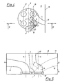
- FIG. 2 shows an exemplary embodiment of a cylinder head according to the invention in plan view
- FIG. 3 shows a section along the line III-III in FIG. 2 on a larger scale
- Fig. 4 shows another embodiment according to the invention
- Fig. 5 shows a section along the line VV in Fig. 4, also on a larger scale
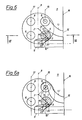
- Fig. 7 shows a section according to the Line VII-VII in Fig. 6 on a larger scale.
- the same or similar parts are provided with the same reference numerals.
- the valve center located above the cylinder bore 22 is designated by 1.
- the angle ⁇ is formed by the straight line 21 connecting the valve center 1 and cylinder center 2, on the one hand, and the radius 20 starting from the valve center 1, which defines the position of the first spiral cross section 3, on the other hand.
- the maximum 4 of the swirl number Dz can be seen at an angle ⁇ of just over 180 °.
- the axes of the intake valves are designated 5 and those of the exhaust valves are designated 6.
- the flange 9 of the inlet channel 10 which is designed as a spiral channel, is arranged on the side of the cylinder head 11 opposite the inlet side, perpendicular to the cylinder axis 7. With 9 'the channel center line is marked, which in Area of the flange 9, approximately in the direction of the cylinder axis.
- the flange 12 of the other inlet channel 13, which is designed as an inclined channel, is parallel to the longitudinal plane 8 of the engine and lies in the plane of the flange 18.
- the flange 14 of the two outlet channels 15 is also arranged parallel to the longitudinal plane 8 of the engine.
- the angle ⁇ relevant for the twist number Dz has the desired value of approximately 180 °.
- the in turn horizontal flange 9 of the inlet channel 10 ' which is designed as a spiral channel, determines between the two in each case by the axes 5 of the inlet valves and the axes 6 of the outlet valves Levels 16 and 17 are located.
- the arrangement of the flanges 14 of the outlet channels 15 is analogous to the exemplary embodiment according to FIGS. 2 and 3.
- the angle ⁇ has the optimum value of 180 °.
- both inlet ducts 10 ′′ and 13 start from the same flange plane 18.
- the channel center line 9 ' points in the direction of the cylinder axis 7, which is illustrated by the normal plane 9a, indicated by dashed lines, on the channel center line 9'.
- the second inlet duct 10 ' has a sufficiently small curvature so that there is no danger of flow separation in any area of the inlet duct 10'.
- the first inlet duct 13, which is representative of all embodiment variants of the invention, is designed as a spiral duct designed with an optimal number of swirls.
Landscapes
- Engineering & Computer Science (AREA)
- Chemical & Material Sciences (AREA)
- Combustion & Propulsion (AREA)
- Mechanical Engineering (AREA)
- General Engineering & Computer Science (AREA)
- Cylinder Crankcases Of Internal Combustion Engines (AREA)
- Combustion Methods Of Internal-Combustion Engines (AREA)
Description
- Die Erfindung betrifft eine mehrzylindrige Brennkraftmaschine mit innerer Gemischbildung, insbesondere Dieselmotor, mit pro Zylinder zwei Einlaßventilen, deren Achsen eine Ebene bestimmen, die angenähert parallel zur Motorlängsebene verläuft, zwei Einlaßkanälen zu den Einlaßventilen, die beide drallerzeugend ausgebildet sind, wobei ein mit optimaler Drallzahl ausgeführter erster Einlaßkanal von einer seitlichen Flanschfläche des Zylinderkopfes ausgeht.
- Bei einer aus der DE-OS 1 906 443 bekannten Brennkraftmaschinen dieser Art gehen beide Einlaßkanäle von der gemeinsamen seitlichen Flanschebene aus. Dies hat den Nachteil, daß für drallerzeugende Kanäle bei gewissen Verhältnissen von Ventilposition und Flanschlage Zwänge entstehen, die eine optimale Auslegung der Kanäle hinsichtlich Drall und Durchfluß verhindern. Unter der Voraussetzung, daß die Verbindung der Ventilmitten parallel zur Motorlängsachse ist, wird es für diese, eine sehr einfache Ventilsteuerung erlaubende Anordnung, sehr schwierig, drallerzeugende Kanäle mit optimalem Durchfluß zu realisieren.
- Es wird dabei einer der Kanäle sowohl als Tangential- oder Spiralkanal optimal den gewünschten Drall der Zylinderladung erzeugen. Um die für den zweiten Einlaßkanal günstigste Position zu finden, ist für einen Spiralkanal ein bestimmter Winkel α, der zwischen der die Ventil- und Zylindermitte verbindenden Geraden einerseits sowie der die Zylindermitte und ersten Spiralquerschnitt verbindenden Geraden andererseits liegt, einzuhalten.
- Der durch Messung gefundene Verlauf der Drallzahl Dz in Abhängigkeit vom Winkel α, läßt das Maximum der Drallzahl Dz bei etwa 180 ° erkennen, sodaß dieser Winkel praktisch anzustreben ist, um optimale Drallwerte zu erreichen.
- Aus konstruktiven Gründen ergeben sich dadurch verschiedene Probleme. Ist nämlich der Zulaufteil des ersten Kanales kurz und strömungsgünstig, so ergibt sich für die Spiralenlage des zweiten Kanals ein Winkel α von etwa 270 °. In diesem Bereich weist die Drallzahl Dz in Abhängigkeit vom Winkel α jedoch ein Minimum auf. Die Wirkung dieses Kanales ist daher durch niedrigeren Drall und geringeren Durchfluß drastisch verschlechtert.
- Bei einer Anordnung, bei der die Spirale des ersten Kanals eine optimale Lage von α = 180 ° aufweist, muß der Kanalzulaufteil des zweiten Kanales stark gekrümmt werden. Eine beliebige Vergrößerung des Krümmungsradius des Kanalzulaufteiles ist wegen Überschneidung mit dem zum Nachbarzylinder führenden Kanal nicht möglich. Es kommt in diesem stark gekrümmten Zulaufteil zu Strömungsablösungen, die die Vorteile der guten Spiralanlage zunichte machen.
- Auch beim Schrägkanal als zweiten Kanal treten ähnlich gelagerte Probleme auf: Da die Wirkung des Schrägkanales darauf beruht, die Luftströmung auf die Zylinderwand zu richten und damit eine drallbehaftete Strömung zu erzeugen, ist bei dieser Ventil-Flansch-Relation auch beim Schrägkanal die Notwendigkeit einer starken Krümmung sofort einsichtig, da andernfalls, bei geradem Schrägkanal, eine dem vom ersten Kanal erzeugten Drall entgegengesetzte Strömung erzeugt wird, die zwar zu hoher Turbulenz, aber zu keiner zylinderaxialen Drehbewegung führen kann.
- Aufgabe der Erfindung ist es, eine Kanalanordnung zu schaffen, die trotz einer Ventilanordnung mehr oder weniger parallel zur Motorachse, eine optimale Drallerzeugung erlaubt.
- Erfindungsgemäß wird dies dadurch erreicht, daß der als Spiralkanal ausgebildete zweite Einlaßkanal so ausgeführt ist, daß zumindest an einer Stelle vor dem Einlaßbereich die Kanalmittellinie etwa in Richtung der Zylinderachse liegt, so daß der zweite Einlaßkanal zur Erreichung einer hohen Drallzahl beider Einlaßkanäle mit einem optimalen Winkel von etwa 180°, der einerseits durch eine den Ventilmittelpunkt und den Zylindermittelpunkt verbindende Gerade gebildet wird, sowie andererseits durch den vom Ventilmittelpunkt ausgehenden Radius, der die Lage eines ersten Eintrittsquerschnittes der Spirale festlegt, ausgeführt wird. Infolge der damit erreichten Freizügigkeit bei der Anordnung der drallerzeugenden Kanäle, können optimale Verhältnisse bezüglich Drall und Strömung erreicht werden.
- In einer weiteren Ausgestaltung der Erfindung ist vorgesehen, daß der zweite Einlaßkanal pro Zylinder von einer in Motorlängsrichtung liegenden Flanschebene ausgeht, die in einem Winkel im Bereich von 90°, vorzugsweise normal, zur Zylinderachse angeordnet ist. Dies hat den Vorteil, daß nun eine optimale Spiralanlage erreicht werden kann, ohne den Zulaufteil unzulässig stark krümmen zu müssen.
- In einer bevorzugten Ausführungsvariante der Erfindung können beide Einlaßkanäle von der gleichen Flanschebene ausgehen. Dadurch kann ein einfaches, kostengünstiges und raumsparendes Einlaßröhrenwerk konzipiert werden.
- Im folgenden wird die Erfindung anhand der schematischen Zeichnungen näher erläutert. Es zeigen: Fig. 1 den Verlauf der Drallzahl Dz in Abhängigkeit von einem Bezugswinkel α, Fig. 2 ein Ausführungsbeispiel eines Zylinderkopfes gemäß der Erfindung in Draufsicht, Fig. 3 einen Schnitt nach der Linie III-III in Fig. 2 in größerem Maßstab, Fig. 4 ein anderes Ausführungsbeispiel gemäß der Erfindung und Fig. 5 einen Schnitt nach der Linie V-V in Fig. 4, ebenfalls in größerem Maßstab, Fig. 6 und 6a weitere Ausführungsbeispiele gemäß der Erfindung in Draufsicht und Fig. 7 dazu einen Schnitt nach der Linie VII-VII in Fig. 6 in größerem Maßstab. Gleiche oder gleichartige Teile sind mit denselben Bezugszeichen versehen.
- In Fig. 1 ist die gemessene Drallzahl Dz in Abhängigkeit vom Winkel α dargestellt. Dabei ist der über der Zylinderbohrung 22 angeordnete Ventilmittelpunkt mit 1 bezeichnet. Der Winkel α wird gebildet von der dem Ventilmittelpunkt 1 und Zylindermittelpunkt 2 verbindenden Geraden 21 einerseits, sowie dem vom Ventilmittelpunkt 1 ausgehenden Radius 20, der die Lage des ersten Spiralquerschnittes 3 festlegt, andererseits. Man kann das Maximum 4 der Drallzahl Dz bei einem Winkel α von knapp über 180 ° erkennen.
- Bei dem Zylinderkopf 11 nach Fig. 2 und 3 sind die Achsen der Einlaßventile mit 5 und jene der Auslaßventile mit 6 bezeichnet. Der Flansch 9 des als Spiralkanal ausgebildeten Einlaßkanales 10 ist auf der der Einlaßseite gegenüberliegenden Seite des Zylinderkopfes 11, senkrecht zur Zylinderache 7, angeordnet. Mit 9′ ist die Kanalmittellinie gekennzeichnet, die im Bereich des Flansches 9, etwa in Richtung der Zylinderachse, liegt. Der Flansch 12 des anderen, als Schrägkanal ausgebildeten Einlaßkanales 13 ist parallel zur Motorlängsebene 8 und liegt in der Flanschebene 18. Der Flansch 14 der beiden Auslaßkanäle 15 ist ebenso parallel zur Motorlängsebene 8 angeordnet. Der für die Drallzahl Dz maßgebliche Winkel α hat hier den angestrebten Wert von ca. 180°. Mit 19 ist der Einlaßbereich des Einlaßkanals 10 unmittelbar vor der Einlaßöffnung 19' in den Zylinder (nicht gezeichnet) bezeichnet. Dieser Einlaßbereich 19 ist, in Richtung der Zylinderachse 7 betrachtet, deckungsgleich mit der Einlaßöffnung 19'.
- Die Ausführung des Zylinderkopfes nach Fig. 4 und 5 unterscheidet sich vom vorgenannten Ausführungsbeispiel im wesentlichen dadurch, daß der wiederum waagrecht liegende Flansch 9 des als Spiralkanal ausgebildeten Einlaßkanales 10' zwischen den beiden jeweils durch die Achsen 5 der Einlaßventile und die Achsen 6 der Auslaßventile bestimmten Ebenen 16 und 17 liegt. Die Anordnung der Flansche 14 der Auslaßkanäle 15 ist analog dem Ausführungsbeispiel nach Fig. 2 und 3. Auch hier hat der Winkel α den Optimalwert von 180°.
- Bei den Ausführungsvarianten in Fig. 6, 6a und 7 gehen beide Einlaßkanäle 10'' und 13 von der gleichen Flanschebene 18 aus. Im Bereich der Motorlängsebene zeigt die Kanalmittellinie 9' in Richtung Zylinderachse 7, was durch die strichliert angedeutet Normalebene 9a auf die Kanalmittellinie 9' veranschaulicht ist. Wie in Fig. 7 ersichtlich, weist der zweite Einlaßkanal 10' eine ausreichend geringe Krümmung auf, sodaß in keinem Bereich des Einlaßkanales 10' die Gefahr einer Strömungsablösung besteht. Bei dem in Fig. 6a dargestellten Ausführungsbeispiel ist der erste Einlaßkanal 13, stellvertretend für sämtliche Ausführungsvarianten der Erfindung, als mit optimaler Drallzahl ausgelegter Spiralkanal ausgeführt.
Claims (3)
- Mehrzylindrige Brennkraftmaschine mit innerer Gemischbildung, insbesondere Dieselmotor, mit pro Zylinder zwei Einlaßventilen (5), deren Achsen eine Ebene (16) bestimmen, die angenähert parallel zu einer durch die Zylinderachsen gebildeten Motorlängsebene (18) verläuft, zwei Einlaßkanälen (10, 10', 13) zu den Einlaßventilen, die beide drallerzeugend ausgeführt sind, wobei ein mit optimaler Drallzahl ausgeführter erster Einlaßkanal (13) von einer seitlichen Flanschfläche (12) des Zylinderkopfes ausgeht, dadurch gekennzeichnet , daß der als Spiralkanal ausgebildete zweite Einlaßkanal (10, 10') so ausgeführt ist, daß zumindest an einer stelle vor dem Einlaßbereich (19) die Kanalmittellinie (9') etwa in Richtung der Zylinderachse (7) liegt, so daß der zweite Einlaßkanal (10, 10') zur Erreichung einer hohen Drallzahl beider Einlaßkanäle mit einem optimalen Winkel (α) von etwa 180°, der einerseits durch eine den Ventilmittelpunkt (1) und den Zylindermittelpunkt (2) verbindende Gerade (21) gebildet wird, sowie andererseits durch den vom Ventilmittelpunkt (1) ausgehenden Radius (20), der die Lage eines ersten Eintrittsquerschnittes (3) der Spirale festlegt, ausgeführt wird.
- Mehrzylindrige Brennkraftmaschine nach Anspruch 1, dadurch gekennzeichnet, daß der zweite Einlaßkanal (10, 10') pro Zylinder von einer in Motorlängsrichtung liegenden Flanschebene (18') ausgeht, die in einem Winkel im Bereich von 90°, vorzugsweise normal, zur Zylinderachse (7) angeordnet ist.
- Mehrzylindrige Brennkraftmaschine nach Anspruch 1, dadurch gekennzeichnet, daß beide Einlaßkanäle (10'; 13) von der gleichen Flanschebene (18) ausgehen.
Applications Claiming Priority (2)
| Application Number | Priority Date | Filing Date | Title |
|---|---|---|---|
| AT1568/91 | 1991-08-07 | ||
| AT156891 | 1991-08-07 |
Publications (2)
| Publication Number | Publication Date |
|---|---|
| EP0527122A1 EP0527122A1 (de) | 1993-02-10 |
| EP0527122B1 true EP0527122B1 (de) | 1994-12-07 |
Family
ID=3516218
Family Applications (1)
| Application Number | Title | Priority Date | Filing Date |
|---|---|---|---|
| EP92890174A Expired - Lifetime EP0527122B1 (de) | 1991-08-07 | 1992-07-27 | Mehrzylindrige Brennkraftmaschine mit innerer Gemischbildung |
Country Status (3)
| Country | Link |
|---|---|
| EP (1) | EP0527122B1 (de) |
| AT (1) | ATE115238T1 (de) |
| DE (1) | DE59200901D1 (de) |
Cited By (3)
| Publication number | Priority date | Publication date | Assignee | Title |
|---|---|---|---|---|
| EP1039110A2 (de) | 1999-03-23 | 2000-09-27 | Bayerische Motoren Werke Aktiengesellschaft | Gegossener Zylinderkopf mit Steuergehäuse für eine mehrzylindrige, flüssigkeitsgekühlte Brennkraftmaschine, insbesondere Dieselmotor |
| DE19820601C2 (de) * | 1997-05-14 | 2002-04-04 | Avl List Gmbh | Mehrzylindrige Brennkraftmaschine mit innerer Gemischbildung |
| US6550447B2 (en) | 2001-01-29 | 2003-04-22 | Avl List Gmbh | Intake port configuration for an internal combustion engine |
Families Citing this family (6)
| Publication number | Priority date | Publication date | Assignee | Title |
|---|---|---|---|---|
| US6109234A (en) * | 1998-10-16 | 2000-08-29 | Ford Global Technologies, Inc. | Cylinder head intake system |
| JP3807207B2 (ja) * | 1999-12-24 | 2006-08-09 | いすゞ自動車株式会社 | 多弁吸気式エンジン |
| JP4325173B2 (ja) * | 2002-11-01 | 2009-09-02 | 三菱自動車工業株式会社 | 直噴式ディーゼルエンジン |
| FR2856743B1 (fr) * | 2003-06-30 | 2005-10-14 | Renault Sa | Circuit d'admission comportant des moyens d'orientation des gaz tangentiellement au mouvement de swirl |
| KR102058755B1 (ko) * | 2012-12-26 | 2020-01-22 | 두산인프라코어 주식회사 | 엔진의 흡기구 구조 |
| CN114135417A (zh) * | 2021-11-22 | 2022-03-04 | 潍柴动力股份有限公司 | 一种缸盖、发动机及车辆 |
Citations (1)
| Publication number | Priority date | Publication date | Assignee | Title |
|---|---|---|---|---|
| DE1906443A1 (de) * | 1969-02-08 | 1970-08-13 | Augsburg Nuernberg Ag Zweignie | Zylinderkopf fuer luftverdichtende,direkteinspritzende Brennkraftmaschinen |
Family Cites Families (3)
| Publication number | Priority date | Publication date | Assignee | Title |
|---|---|---|---|---|
| DE1956351B2 (de) * | 1969-11-08 | 1977-11-17 | Süddeutsche Bremsen-AG, 8000 München | Drallerzeugender einlasskanal |
| DE2235050A1 (de) * | 1972-07-17 | 1974-01-31 | Elsbett | Drallbildender kanal, insbesondere im ansaugsystem von hubkolben-brennkraftmaschinen |
| US4703729A (en) * | 1986-10-14 | 1987-11-03 | Kubota Ltd. | Intake system with double intake ports for internal combustion engine |
-
1992
- 1992-07-27 AT AT92890174T patent/ATE115238T1/de not_active IP Right Cessation
- 1992-07-27 EP EP92890174A patent/EP0527122B1/de not_active Expired - Lifetime
- 1992-07-27 DE DE59200901T patent/DE59200901D1/de not_active Expired - Fee Related
Patent Citations (1)
| Publication number | Priority date | Publication date | Assignee | Title |
|---|---|---|---|---|
| DE1906443A1 (de) * | 1969-02-08 | 1970-08-13 | Augsburg Nuernberg Ag Zweignie | Zylinderkopf fuer luftverdichtende,direkteinspritzende Brennkraftmaschinen |
Cited By (3)
| Publication number | Priority date | Publication date | Assignee | Title |
|---|---|---|---|---|
| DE19820601C2 (de) * | 1997-05-14 | 2002-04-04 | Avl List Gmbh | Mehrzylindrige Brennkraftmaschine mit innerer Gemischbildung |
| EP1039110A2 (de) | 1999-03-23 | 2000-09-27 | Bayerische Motoren Werke Aktiengesellschaft | Gegossener Zylinderkopf mit Steuergehäuse für eine mehrzylindrige, flüssigkeitsgekühlte Brennkraftmaschine, insbesondere Dieselmotor |
| US6550447B2 (en) | 2001-01-29 | 2003-04-22 | Avl List Gmbh | Intake port configuration for an internal combustion engine |
Also Published As
| Publication number | Publication date |
|---|---|
| DE59200901D1 (de) | 1995-01-19 |
| ATE115238T1 (de) | 1994-12-15 |
| EP0527122A1 (de) | 1993-02-10 |
Similar Documents
| Publication | Publication Date | Title |
|---|---|---|
| EP0627264B1 (de) | Injektor für Flotationseinrichtungen | |
| DE69401829T2 (de) | Brennkraftmaschine mit mehreren Einlassventilen | |
| DE60126690T2 (de) | Abgaskrümmer einer Brennkraftmaschine | |
| EP0565923A1 (de) | Mischeinrichtung zum Mischen von zwei Flüssigkeiten bei konstantem Gemischvolumenstrom zur Versorgung des Stoffauflaufs einer Papiermaschine | |
| EP0198197A2 (de) | Differentialdruckströmungssonde | |
| EP0710506A1 (de) | Düsenanordnung für eine Farbspritzpistole | |
| EP0527122A1 (de) | Mehrzylindrige Brennkraftmaschine mit innerer Gemischbildung | |
| DE1575057A1 (de) | Spritzkopf zum Verspruehen von Fluessigkeiten,insbesondere von Farben,Lacken od. dgl. | |
| DE3815211C2 (de) | ||
| DE3922489A1 (de) | Luftmessvorrichtung | |
| DE2844504A1 (de) | Brennstoffzufuehrungsvorrichtung fuer einen verbrennungsmotor | |
| AT402431B (de) | Zweitakt-brennkraftmaschine | |
| DE69707379T2 (de) | Dampfauslassanordnung | |
| DE10261011A1 (de) | Vorrichtung zum Herstellen eines gesponnenen Fadens | |
| DE3236971A1 (de) | Wirbelduese zum einwirken auf ein faserbuendel | |
| DE102016123993B4 (de) | Flüssigkeitsstrahl-Verschlussdüse | |
| AT402434B (de) | Zylinderkopf für brennkraftmaschinen mit zwei einlassventilen pro zylinder | |
| AT404287B (de) | Saugrohr einer brennkraftmaschine | |
| EP0489225A1 (de) | Doppeldraht-Zwirnspindel mit druckluftbetätigter Einfädelvorrichtung | |
| DE19820601C2 (de) | Mehrzylindrige Brennkraftmaschine mit innerer Gemischbildung | |
| CH664192A5 (de) | Ventilsitzring fuer einen einlasskanal von ventilgesteuerten brennkraftmaschinen. | |
| DE19750068C1 (de) | Axial-Hohlkegeldüse zum Versprühen flüssiger Medien | |
| EP0207443B1 (de) | Abgassammelrohr für eine Brennkraftmaschine | |
| DE19814187A1 (de) | Einsaugdrallkanal für eine Verbrennungskraftmaschine | |
| DE3114386C2 (de) | Brennstoffeinspritzventil für Dieselbremskraftmaschinen |
Legal Events
| Date | Code | Title | Description |
|---|---|---|---|
| PUAI | Public reference made under article 153(3) epc to a published international application that has entered the european phase |
Free format text: ORIGINAL CODE: 0009012 |
|
| AK | Designated contracting states |
Kind code of ref document: A1 Designated state(s): AT DE FR GB IT |
|
| ITCL | It: translation for ep claims filed |
Representative=s name: MODIANO & ASSOCIATI S.R.L. |
|
| 17P | Request for examination filed |
Effective date: 19930113 |
|
| GBC | Gb: translation of claims filed (gb section 78(7)/1977) | ||
| EL | Fr: translation of claims filed | ||
| 17Q | First examination report despatched |
Effective date: 19940520 |
|
| GRAA | (expected) grant |
Free format text: ORIGINAL CODE: 0009210 |
|
| AK | Designated contracting states |
Kind code of ref document: B1 Designated state(s): AT DE FR GB IT |
|
| REF | Corresponds to: |
Ref document number: 115238 Country of ref document: AT Date of ref document: 19941215 Kind code of ref document: T |
|
| REF | Corresponds to: |
Ref document number: 59200901 Country of ref document: DE Date of ref document: 19950119 |
|
| GBT | Gb: translation of ep patent filed (gb section 77(6)(a)/1977) |
Effective date: 19941222 |
|
| ET | Fr: translation filed | ||
| ITF | It: translation for a ep patent filed | ||
| PLBE | No opposition filed within time limit |
Free format text: ORIGINAL CODE: 0009261 |
|
| 26N | No opposition filed | ||
| PGFP | Annual fee paid to national office [announced via postgrant information from national office to epo] |
Ref country code: GB Payment date: 20010116 Year of fee payment: 9 |
|
| PGFP | Annual fee paid to national office [announced via postgrant information from national office to epo] |
Ref country code: FR Payment date: 20010125 Year of fee payment: 9 |
|
| PGFP | Annual fee paid to national office [announced via postgrant information from national office to epo] |
Ref country code: AT Payment date: 20010726 Year of fee payment: 10 |
|
| PG25 | Lapsed in a contracting state [announced via postgrant information from national office to epo] |
Ref country code: GB Free format text: LAPSE BECAUSE OF NON-PAYMENT OF DUE FEES Effective date: 20010727 |
|
| GBPC | Gb: european patent ceased through non-payment of renewal fee |
Effective date: 20010727 |
|
| PG25 | Lapsed in a contracting state [announced via postgrant information from national office to epo] |
Ref country code: FR Free format text: LAPSE BECAUSE OF NON-PAYMENT OF DUE FEES Effective date: 20020329 |
|
| REG | Reference to a national code |
Ref country code: FR Ref legal event code: ST |
|
| PG25 | Lapsed in a contracting state [announced via postgrant information from national office to epo] |
Ref country code: AT Free format text: LAPSE BECAUSE OF NON-PAYMENT OF DUE FEES Effective date: 20020727 |
|
| PGFP | Annual fee paid to national office [announced via postgrant information from national office to epo] |
Ref country code: DE Payment date: 20050718 Year of fee payment: 14 |
|
| PG25 | Lapsed in a contracting state [announced via postgrant information from national office to epo] |
Ref country code: IT Free format text: LAPSE BECAUSE OF NON-PAYMENT OF DUE FEES;WARNING: LAPSES OF ITALIAN PATENTS WITH EFFECTIVE DATE BEFORE 2007 MAY HAVE OCCURRED AT ANY TIME BEFORE 2007. THE CORRECT EFFECTIVE DATE MAY BE DIFFERENT FROM THE ONE RECORDED. Effective date: 20050727 |
|
| PG25 | Lapsed in a contracting state [announced via postgrant information from national office to epo] |
Ref country code: DE Free format text: LAPSE BECAUSE OF NON-PAYMENT OF DUE FEES Effective date: 20070201 |