EP0526406A2 - Flat bed knitting machine - Google Patents
Flat bed knitting machine Download PDFInfo
- Publication number
- EP0526406A2 EP0526406A2 EP92810571A EP92810571A EP0526406A2 EP 0526406 A2 EP0526406 A2 EP 0526406A2 EP 92810571 A EP92810571 A EP 92810571A EP 92810571 A EP92810571 A EP 92810571A EP 0526406 A2 EP0526406 A2 EP 0526406A2
- Authority
- EP
- European Patent Office
- Prior art keywords
- knitting machine
- cam holders
- machine according
- driven
- cam
- Prior art date
- Legal status (The legal status is an assumption and is not a legal conclusion. Google has not performed a legal analysis and makes no representation as to the accuracy of the status listed.)
- Granted
Links
Images
Classifications
-
- D—TEXTILES; PAPER
- D04—BRAIDING; LACE-MAKING; KNITTING; TRIMMINGS; NON-WOVEN FABRICS
- D04B—KNITTING
- D04B7/00—Flat-bed knitting machines with independently-movable needles
- D04B7/04—Flat-bed knitting machines with independently-movable needles with two sets of needles
-
- D—TEXTILES; PAPER
- D04—BRAIDING; LACE-MAKING; KNITTING; TRIMMINGS; NON-WOVEN FABRICS
- D04B—KNITTING
- D04B7/00—Flat-bed knitting machines with independently-movable needles
-
- D—TEXTILES; PAPER
- D04—BRAIDING; LACE-MAKING; KNITTING; TRIMMINGS; NON-WOVEN FABRICS
- D04B—KNITTING
- D04B15/00—Details of, or auxiliary devices incorporated in, weft knitting machines, restricted to machines of this kind
- D04B15/38—Devices for supplying, feeding, or guiding threads to needles
- D04B15/40—Holders or supports for thread packages
- D04B15/42—Frames for assemblies of two or more reels
-
- D—TEXTILES; PAPER
- D04—BRAIDING; LACE-MAKING; KNITTING; TRIMMINGS; NON-WOVEN FABRICS
- D04B—KNITTING
- D04B15/00—Details of, or auxiliary devices incorporated in, weft knitting machines, restricted to machines of this kind
- D04B15/38—Devices for supplying, feeding, or guiding threads to needles
- D04B15/54—Thread guides
- D04B15/56—Thread guides for flat-bed knitting machines
-
- D—TEXTILES; PAPER
- D04—BRAIDING; LACE-MAKING; KNITTING; TRIMMINGS; NON-WOVEN FABRICS
- D04B—KNITTING
- D04B15/00—Details of, or auxiliary devices incorporated in, weft knitting machines, restricted to machines of this kind
- D04B15/94—Driving-gear not otherwise provided for
- D04B15/96—Driving-gear not otherwise provided for in flat-bed knitting machines
-
- D—TEXTILES; PAPER
- D04—BRAIDING; LACE-MAKING; KNITTING; TRIMMINGS; NON-WOVEN FABRICS
- D04B—KNITTING
- D04B7/00—Flat-bed knitting machines with independently-movable needles
- D04B7/24—Flat-bed knitting machines with independently-movable needles for producing patterned fabrics
- D04B7/26—Flat-bed knitting machines with independently-movable needles for producing patterned fabrics with colour patterns
Definitions
- the subject of the present invention is a straight knitting machine comprising two needle beds, at least one pair of opposite cam holders for driving the needles, means for driving these cam holders along the needle beds, several thread guides. likely to move on bars above the needle beds, means for driving these thread guides and means for controlling the movements of the cam holders and thread guides.
- Such a machine is known, for example, from patent application EP 0 246 364.
- the cam holders are mounted on a carriage in the form of an arch overlapping the needle beds and the bars. -rageurs on which the wire guides move.
- Such a form of carriage has been used practically since the invention of knitting machines with two needle beds and has hitherto been considered as a compulsory design, in order to ensure the synchronized movement of the two cam holders, despite the drawbacks that it presents for an Intarsia knitting machine.
- These drawbacks lie in the fact that the knitting yarns must be brought to the yarn guides almost horizontally so as not to be in the path of the carriage. For this purpose, the wires must pass over references at one end of the machine.
- the Dubied company sought to solve this problem by extending the carriage arc transversely.
- the carriage arc extended in the extension of the machine, considerably increasing the size of the machine.
- the object of the present invention is to obviate the drawbacks described above and to propose a construction making it possible to considerably increase the working speed of the machine, as well as the number of knitted threads.
- the knitting machine according to the invention is characterized in that the cam holders of each pair are independent and that they are driven individually and mutually controlled.
- the knitting machine according to the invention therefore practically no longer has a carriage and, contrary to the ideas acquired, synchronization of the cam holders is perfectly possible without rigid connection between these cam holders.
- the mutual control of the cam holders can be ensured by mechanical or electronic means.
- the thread guides are preferably driven individually, each by its own motor, which makes it possible to position the thread guides at will and therefore the creation of new mesh structures, as well as the combination of different structures and Intarsia.
- Figure 1 schematically shows a front view of a knitting machine.
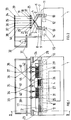
- Figure 2 is a sectional view along II-II of Figure 1.
- the knitting machine shown comprises, like the usual machines, a frame 1 carrying two needle beds 2 and 3 mounted in V.
- a frame 1 carrying two needle beds 2 and 3 mounted in V.
- needles and keys which are driven by two cam holders 4 and 5, double fall in the example considered.
- the cam holders 4 and 5 are not mounted on a carriage, but are independent.
- the cam holder 4 is slidably mounted on two parallel bars 6 and 7.
- the cam holder 5 is mounted on two parallel cylindrical bars 8 and 9.
- the cam holder 4 is attached to a toothed belt 10 s' extending over almost the entire length of the machine.
- the toothed belt 10 is driven by a toothed wheel 11 which is itself driven by a first electric motor 12.
- the cam holder 5 is attached to a second toothed belt 13 driven by a toothed wheel 14 which is itself driven by a second motor 15.
- the toothed belts pass over references 16. These references can also be toothed. So as to have two perfectly identical toothed belts 10 and 13, these belts are preferably obtained by sharing a notched belt along. The belts obtained are thus perfectly identical, both in shape and in structure. They therefore have in particular the same elasticity characteristics.
- each of these bars 17 to 22 is slidably mounted a thread guide 25, respectively, 26, 27, 28, 29, 30.
- a thread spout such as 31.
- Each thread guide is driven along its bar by means of a small individual electric motor via a belt or a worm (not shown). The removal of the cart frees up all the space above the beds, which allows freely arrange the bars of the wire guides at the height and with the spacing which is most suitable for gripping and driving the wires. It is furthermore without other possibility to increase the number of bars, that is to say of thread guide and consequently the number of different threads capable of being knitted.
- a bobbin support 31 on which are mounted six bobbins such as the bobbin 32.
- the bobbins have not been shown in FIG. 1.
- wire references 33, 34, 35, 36, 37, 38 are mounted wire references 33, 34, 35, 36, 37, 38.
- the motors 12 and 15, as well as the motors of the wire guides are controlled by a programmable logic processing unit with microprocessor. Each motor is controlled individually. This means that the cam holders 4 and 5 can be momentarily desynchronized to be offset with respect to each other.
- the toothed wheels 11 and 14 driving the toothed belts could be integral with a common shaft driven by a single motor.
- the references 16, also toothed could be rigidly linked by a common axis.
- the cam holders could be driven by other means, for example, by means of an endless screw, which could replace one of the guide bars.
- Each bar could carry two thread guides, one thread guide on each side of the bar.
Abstract
Description
La présente invention a pour objet une machine à tricoter rectiligne comprenant deux fontures, au moins une paire de porte-cames opposées pour l'entraînement des aiguilles, des moyens d'entraînement de ces porte-cames le long des fontures, plusieurs guide-fil susceptibles de se déplacer sur des barres au-dessus des fontures, des moyens d'entraînement de ces guide-fil et des moyens de commande des déplacements des porte-cames et des guide-fil.The subject of the present invention is a straight knitting machine comprising two needle beds, at least one pair of opposite cam holders for driving the needles, means for driving these cam holders along the needle beds, several thread guides. likely to move on bars above the needle beds, means for driving these thread guides and means for controlling the movements of the cam holders and thread guides.
Une telle machine est connue, par exemple, de la demande de brevet EP 0 246 364. Dans cette machine, comme dans toutes les machines connues, les porte-cames sont montés sur un chariot en forme d'arceau chevauchant les fontures et les barres-rageurs sur lesquelles se déplacent les guide-fil. Une telle forme de chariot est utilisée pratiquement depuis l'invention des machines à tricoter à deux fontures et elle a été considérée jusqu'ici comme une conception obligatoire, afin d'assurer le déplacement synchronisé des deux porte-cames, malgré les inconvénients qu'elle présente pour une machine à tricoter des tricots Intarsia. Ces inconvénients résident dans le fait que les fils à tricoter doivent être amenés aux guide-fil presque horizontalement pour ne pas se trouver dans la trajectoire du chariot. A cet effet les fils doivent passer sur des renvois à l'une des extrémités de la machine. Il en résulte que pour un sens de déplacement du chariot la traction sur le fil est importante, tandis que lors du déplacement du chariot dans l'autre sens, le fil doit être retiré dans l'autre sens afin que le mou produit sur le fil ne provoque pas la chute du fil sur les fontures. Ces conditions, qui ont du être respectées jusqu'ici, limitent la vitesse de déplacement du chariot, ainsi que le nombre de fils de couleurs différentes susceptibles d'être tricotés. Or, les performances actuelles des moyens électroniques et mécaniques sont telles que, sans ces inconvénients, il serait sans autre possible de travailler à une vitesse sensiblement plus grande que la vitesse actuelle et avec davantage de fils.Such a machine is known, for example, from patent application EP 0 246 364. In this machine, as in all known machines, the cam holders are mounted on a carriage in the form of an arch overlapping the needle beds and the bars. -rageurs on which the wire guides move. Such a form of carriage has been used practically since the invention of knitting machines with two needle beds and has hitherto been considered as a compulsory design, in order to ensure the synchronized movement of the two cam holders, despite the drawbacks that it presents for an Intarsia knitting machine. These drawbacks lie in the fact that the knitting yarns must be brought to the yarn guides almost horizontally so as not to be in the path of the carriage. For this purpose, the wires must pass over references at one end of the machine. It follows that for a direction of movement of the carriage the traction on the wire is important, while during the displacement of the carriage in the other direction, the wire must be withdrawn in the other direction so that the slack produced on the wire does not cause the thread to fall on the needle beds. These conditions, which have had to be observed so far, limit the speed of movement of the carriage, as well as the number of threads of different colors capable of being knitted. However, the current performance of electronic and mechanical means is such that, without these drawbacks, it would be without other possibility to work at a speed substantially greater than the current speed and with more son.
Dans les années 1920 la maison Dubied a cherché à résoudre ce problème en rallongeant l'arc de chariot transversalement. L'arc de chariot s'étendait dans le prolongement de la machine, en augmentant considérablement l'encombrement de la machine.In the 1920s, the Dubied company sought to solve this problem by extending the carriage arc transversely. The carriage arc extended in the extension of the machine, considerably increasing the size of the machine.
La présente invention a pour but d'obvier aux inconvénients décrits ci-dessus et de proposer une construction permettant d'augmenter considérablement la vitesse de travail de la machine, ainsi que le nombre de fils tricotés.The object of the present invention is to obviate the drawbacks described above and to propose a construction making it possible to considerably increase the working speed of the machine, as well as the number of knitted threads.
La machine à tricoter selon l'invention est caractérisée en ce que les porte-cames de chaque paire sont indépendants et qu'ils sont entraînés individuellement et mutuellement asservis.The knitting machine according to the invention is characterized in that the cam holders of each pair are independent and that they are driven individually and mutually controlled.
La machine à tricoter selon l'invention ne comporte donc pratiquement plus de chariot et, contrairement aux idées acquises, une synchronisation des porte-cames est parfaitement possible sans liaison rigide entre ces porte-cames.The knitting machine according to the invention therefore practically no longer has a carriage and, contrary to the ideas acquired, synchronization of the cam holders is perfectly possible without rigid connection between these cam holders.
L'asservissement mutuel des porte-cames peut être assuré par des moyens mécaniques ou électroniques.The mutual control of the cam holders can be ensured by mechanical or electronic means.
Jusqu'ici, un chariot semblait également nécessaire pour assurer l'alignement transversal des porte-cames. Or, il s'avère que les porte-cames ne doivent pas être nécessairement alignés transversalement, mais qu'il peut être au contraire judicieux de les décaler, par exemple pour serrer ou desserrer les mailles à volonté. La machine à tricoter selon l'invention permet précisément de décaler les porte-cames à volonté. Cette faculté ouvre d'immenses possibilités de tricotage et donne une très grande souplesse d'utilisation.Until now, a carriage also seemed necessary to ensure the transverse alignment of the cam holders. However, it turns out that the cam holders do not necessarily have to be transversely aligned, but that it may on the contrary be wise to offset them, for example to tighten or loosen the meshes at will. The knitting machine according to the invention makes it possible precisely to shift the cam holders at will. This ability opens up immense knitting possibilities and gives great flexibility of use.
Dans une telle machine à tricoter, les guide-fil sont de préférence entraînés individuellement, chacun par son propre moteur, ce qui permet de positionner les guide-fil à volonté et partant la réalisation de nouvelles structures de mailles, ainsi que la combinaison de différentes structures et d'Intarsia.In such a knitting machine, the thread guides are preferably driven individually, each by its own motor, which makes it possible to position the thread guides at will and therefore the creation of new mesh structures, as well as the combination of different structures and Intarsia.
Le dessin annexé représente, à titre d'exemple, une forme d'exécution de l'invention.The accompanying drawing shows, by way of example, an embodiment of the invention.
La figure 1 représente schématiquement une vue de face d'une machine à tricoter.Figure 1 schematically shows a front view of a knitting machine.
La figure 2 est une vue en coupe selon II-II de la figure 1.Figure 2 is a sectional view along II-II of Figure 1.
La machine à tricoter représentée comprend, comme les machines usuelles, un bâti 1 portant deux fontures 2 et 3 montées en V. Dans chacune des fontures 2 et 3 sont disposées des aiguilles et des clavettes dont l'entraînement est assuré par deux porte-cames 4 et 5, à double chute dans l'exemple considéré.The knitting machine shown comprises, like the usual machines, a frame 1 carrying two
Dans leur nouvelle conception, les porte-cames 4 et 5 ne sont pas montés sur un chariot, mais sont indépendants. Le porte-cames 4 est monté coulissant sur deux barres parallèles 6 et 7. De manière analogue, le porte-cames 5 est monté sur deux barres parallèles cylindriques 8 et 9. Le porte-cames 4 est attaché à une courroie crantée 10 s'étendant sur presque toute la longueur de la machine. La courroie crantée 10 est entraînée par une roue dentée 11 elle-même entraînée par un premier moteur électrique 12. De manière analogue, le porte-cames 5 est attaché à une seconde courroie crantée 13 entraînée par une roue dentée 14 elle-même entraînée par un second moteur 15. A l'autre extrémité de la machine, les courroies crantées passent sur des renvois 16. Ces renvois peuvent être également dentés. De manière à avoir deux courroies crantées 10 et 13 parfaitement identiques, ces courroies sont de préférence obtenues par le partage en long d'une courroie crantée. Les courroies obtenues sont ainsi parfaitement identiques, tant dans leur forme que dans leur structure. Elles présentent donc notamment les mêmes caractéristiques d'élasticité.In their new design, the
Au-dessus des fontures 2 et 3 s'étendent un certain nombre de barres, dans l'exemple représenté six barres 17, 18, 19, 20, 21, 22, parallèlement aux fontures et portées à leurs extrémités par deux montants 23 et 24. Sur chacune de ces barres 17 à 22 est monté coulissant un guide-fil 25, respectivement, 26, 27, 28, 29, 30. Sur chaque guide-fil est monté un bec-fil tel que 31. Chaque guide-fil est entraîné le long de sa barre au moyen d'un petit moteur électrique individuel par l'intermédiaire d'une courroie ou d'une vis sans fin (non représentée). La suppression du chariot libère tout l'espace au-dessus des fontures, ce qui permet de disposer librement les barres des guide-fil à la hauteur et avec l'écartement qui convient le mieux à la saisie et à l'entraînement des fils. Il est en outre sans autre possible d'augmenter le nombre des barres, c'est-à-dire de guide-fil et par conséquent le nombre de fils différents susceptibles d'être tricotés.Above the
En arrière des fontures on trouve, de manière connue, un support de bobines 31 sur lequel sont montés six bobines tels que la bobine 32. Les bobines n'ont pas été représentées à la figure 1. En face de chacune des bobines et au-dessus de chaque guide-fil correspondant sont montés des renvois de fils 33, 34, 35, 36, 37, 38.Behind the needle beds there is, in a known manner, a bobbin support 31 on which are mounted six bobbins such as the
Les moteurs 12 et 15, ainsi que les moteurs des guide-fils sont commandés par une unité logique de traitement programmable à micro-processeur. Chaque moteur est commandé individuellement. Cela signifie que les porte-cames 4 et 5 peuvent être momentanément désynchronisés pour être décalés l'un par rapport à l'autre.The
Le principal avantage de la machine à tricoter représenté découle immédiatement du dessin. On voit que les fils 39 à 44 vont vers chacun des guide-fil par le plus court chemin. Supposons que les porte-cames se déplacent dans le sens de la flèche. Les guide-fil 26 et 30 sont entraînés par leurs moteurs respectifs de manière synchronisée au déplacement des porte-cames et les fils 40 et 44 sont tricotés. La tension sur le fil 40 est minimale. Pour changer de fil, il suffit d'écarter le fil tricoté de la trajectoire des aiguilles et d'amener un autre fil dans cette trajectoire en déplaçant son guide-fil de manière adéquate, par exemple comme décrit dans la demande de brevet EP 0 415 512.The main advantage of the knitting machine shown is immediately apparent from the design. We see that the
Il devient possible de travailler des fils plus fragiles que les fils actuels. Il est possible d'augmenter considérablement le nombre de barres et de guide-fil, par exemple de porter ce nombre à vingt, ce qui permet de tricoter en vingt couleurs différentes.It becomes possible to work with more fragile threads than current threads. It is possible to considerably increase the number of bars and thread guides, for example to increase this number to twenty, which allows knitting in twenty different colors.
La possibilité de décaler à volonté les porte-cames l'un par rapport à l'autre ouvre d'immenses possibilités de tricotage. Un faible décalage permet de resserrer ou au contraire d'agrandir des mailles. Un décalage plus grand devrait permettre de transformer une machine à simple chute en machine à double chute. Les possibilités ouvertes sont immenses.The possibility of shifting the cam holders at will relative to each other opens up immense knitting possibilities. A slight offset makes it possible to tighten or on the contrary to enlarge the meshes. A larger offset should make it possible to transform a single fall machine into a double fall machine. The possibilities are endless.
Selon une variante plus simple, les roues dentées 11 et 14 entraînant les courroies crantées pourraient être solidaires d'un arbre commun entraîné par un seul moteur. De même, les renvois 16, également dentés, pourraient être rigidement liés par un axe commun. Une telle exécution, avec des courroies crantées jumelles, permet d'assurer l'alignement des porte-cames comme c'est le cas sur un chariot traditionnel. La liaison rigide entre les roues dentées compense les écarts possibles dus à l'élasticité des courroies.According to a simpler variant, the
Les porte-cames pourraient être entraînés par d'autres moyens, par exemple, au moyen d'une vis sans fin, qui pourrait remplacer l'une des barres de guidage.The cam holders could be driven by other means, for example, by means of an endless screw, which could replace one of the guide bars.
Chaque barre pourrait porter deux guide-fil, soit un guide-fil de chaque côté de la barre.Each bar could carry two thread guides, one thread guide on each side of the bar.
La technique décrite s'applique bien entendu aussi à une machine double.The technique described applies of course also to a double machine.
Claims (8)
Applications Claiming Priority (2)
| Application Number | Priority Date | Filing Date | Title |
|---|---|---|---|
| CH229991A CH686089A5 (en) | 1991-08-02 | 1991-08-02 | Flatbed knitting machine. |
| CH2299/91 | 1991-08-02 |
Publications (3)
| Publication Number | Publication Date |
|---|---|
| EP0526406A2 true EP0526406A2 (en) | 1993-02-03 |
| EP0526406A3 EP0526406A3 (en) | 1993-04-07 |
| EP0526406B1 EP0526406B1 (en) | 1996-04-24 |
Family
ID=4230544
Family Applications (1)
| Application Number | Title | Priority Date | Filing Date |
|---|---|---|---|
| EP92810571A Revoked EP0526406B1 (en) | 1991-08-02 | 1992-07-24 | Flat bed knitting machine |
Country Status (9)
| Country | Link |
|---|---|
| US (1) | US5417087A (en) |
| EP (1) | EP0526406B1 (en) |
| JP (1) | JP3309321B2 (en) |
| KR (1) | KR930004537A (en) |
| CH (1) | CH686089A5 (en) |
| DE (1) | DE69210132T2 (en) |
| ES (1) | ES2086712T3 (en) |
| GR (1) | GR3020359T3 (en) |
| MX (1) | MX9204497A (en) |
Cited By (8)
| Publication number | Priority date | Publication date | Assignee | Title |
|---|---|---|---|---|
| FR2874221A1 (en) * | 2004-08-11 | 2006-02-17 | Steiger S A C Sa Suisse Atel C | WIRE GUIDE DRIVE FOR KNITTING MACHINE |
| FR2878261A1 (en) * | 2004-11-23 | 2006-05-26 | Steiger S A C Sa Suisse Atel C | WIRE DISTRIBUTOR FOR RECTILINE MACHINE |
| CN102653898A (en) * | 2012-04-18 | 2012-09-05 | 武汉纺织大学 | Double-system computerized flat knitting machine head device |
| WO2019192111A1 (en) * | 2018-04-04 | 2019-10-10 | 浙江睿丰智能科技有限公司 | Main transmission mechanism for flat knitting machine |
| EP3575462A3 (en) * | 2018-05-22 | 2020-04-22 | Fabdesigns, Inc. | Knitting machine, textile article and method of knitting a textile article on a flat knitting machine |
| US11168416B2 (en) | 2018-05-02 | 2021-11-09 | Fabdesigns, Inc. | System and method for knitting shoe uppers |
| US11186930B2 (en) | 2018-05-17 | 2021-11-30 | Fabdesigns, Inc. | System and method for knitting shoe uppers |
| US11828009B2 (en) | 2018-05-16 | 2023-11-28 | Fabdesigns, Inc. | System and method of unspooling a material into a textile machine |
Families Citing this family (10)
| Publication number | Priority date | Publication date | Assignee | Title |
|---|---|---|---|---|
| US5623840A (en) * | 1992-07-08 | 1997-04-29 | Tecnit-Technische Textilien Und Systeme Gmbh | Process for production of weave-knit material |
| DE19538936A1 (en) * | 1995-10-18 | 1997-05-07 | Beckmann Wolfgang Dr | Two bed knitting machine with electronic replacing fixed carriage link |
| ES2176943T3 (en) * | 1998-12-23 | 2002-12-01 | Luigi Omodeo Zorini | ACTUATOR DEVICE FOR CONTROLLED MOVEMENT OF MEMBERS IN TRICOTOSAS. |
| JP3968074B2 (en) * | 2001-05-25 | 2007-08-29 | 株式会社島精機製作所 | Method of knitting an intarsia pattern knitted fabric and a knitting program generation device therefor |
| US7011945B2 (en) | 2001-12-21 | 2006-03-14 | Eastman Kodak Company | Random array of micro-spheres for the analysis of nucleic acids |
| KR101025146B1 (en) * | 2003-02-20 | 2011-03-31 | 가부시키가이샤 시마세이키 세이사쿠쇼 | Carriage drive device in weft knitting machine |
| JP5260311B2 (en) * | 2006-12-25 | 2013-08-14 | 株式会社島精機製作所 | Method for knitting tubular knitted fabric and flat knitting machine |
| EP2206815B1 (en) * | 2007-09-07 | 2014-02-12 | Shima Seiki Mfg., Ltd | Weft knitting machine, and its feeding method |
| CN101910491B (en) * | 2007-12-25 | 2012-07-18 | 株式会社岛精机制作所 | Weft knitting machine, and control method for mobile carrier in the weft knitting machine |
| EP3115491B2 (en) * | 2015-07-09 | 2022-08-03 | H. Stoll AG & Co. KG | Flat knitting machine |
Citations (6)
| Publication number | Priority date | Publication date | Assignee | Title |
|---|---|---|---|---|
| US3733856A (en) * | 1971-06-12 | 1973-05-22 | Shima Idea Center Co Ltd | Flat knitting machine |
| DE2415886A1 (en) * | 1974-04-02 | 1975-10-30 | Stoll & Co H | Flatbed knitter slide drive - uses separate and synchronised drives to determine length of slide travel |
| GB2195360A (en) * | 1986-09-10 | 1988-04-07 | Stoll & Co H | Apparatus for controlling a flat knitting machine |
| DE8424135U1 (en) * | 1984-08-14 | 1988-04-07 | Universal Maschinenfabrik Dr. Rudolf Schieber Gmbh & Co Kg, 7084 Westhausen, De | |
| EP0401002A2 (en) * | 1989-05-30 | 1990-12-05 | Brother Kogyo Kabushiki Kaisha | Yarn exchange device for a flat bed knitting machine |
| EP0415512A1 (en) * | 1989-01-06 | 1991-03-06 | Ikenaga Co., Ltd. | Pattern control device for flat knitting machines |
Family Cites Families (8)
| Publication number | Priority date | Publication date | Assignee | Title |
|---|---|---|---|---|
| GB1445374A (en) | 1973-02-26 | 1976-08-11 | Sigma Instruments Inc | Selective positioning system particularly for onctrolling guide bars of knitting machines |
| CH612455A5 (en) * | 1977-07-25 | 1979-07-31 | Dubied & Cie Sa E | |
| IE821584L (en) * | 1982-06-30 | 1983-12-30 | William Cashman | Metering device |
| DE3429913C1 (en) * | 1984-08-14 | 1986-04-17 | Universal Maschinenfabrik Dr. Rudolf Schieber GmbH & Co KG, 7081 Westhausen | Double-head flat knitting machine |
| DE3532943A1 (en) * | 1985-09-14 | 1987-03-26 | Stoll & Co H | FLAT KNITTING MACHINE |
| DD244774A1 (en) * | 1985-12-24 | 1987-04-15 | Textima Veb K | FLAT KNITTING MACHINE |
| DE3702050A1 (en) * | 1987-01-24 | 1988-08-04 | Stoll & Co H | FLAT KNITTING MACHINE WITH DATA PROCESSING DEVICE |
| US5014524A (en) * | 1989-08-23 | 1991-05-14 | Adrian Smilovici | Flat bed knitting machine having plural carriages |
-
1991
- 1991-08-02 CH CH229991A patent/CH686089A5/en not_active IP Right Cessation
-
1992
- 1992-07-03 KR KR1019920011846A patent/KR930004537A/en not_active Application Discontinuation
- 1992-07-03 JP JP20026492A patent/JP3309321B2/en not_active Expired - Fee Related
- 1992-07-24 DE DE69210132T patent/DE69210132T2/en not_active Revoked
- 1992-07-24 EP EP92810571A patent/EP0526406B1/en not_active Revoked
- 1992-07-24 ES ES92810571T patent/ES2086712T3/en not_active Expired - Lifetime
- 1992-07-31 MX MX9204497A patent/MX9204497A/en unknown
-
1993
- 1993-08-23 US US08/110,439 patent/US5417087A/en not_active Expired - Fee Related
-
1996
- 1996-06-27 GR GR960401728T patent/GR3020359T3/en unknown
Patent Citations (6)
| Publication number | Priority date | Publication date | Assignee | Title |
|---|---|---|---|---|
| US3733856A (en) * | 1971-06-12 | 1973-05-22 | Shima Idea Center Co Ltd | Flat knitting machine |
| DE2415886A1 (en) * | 1974-04-02 | 1975-10-30 | Stoll & Co H | Flatbed knitter slide drive - uses separate and synchronised drives to determine length of slide travel |
| DE8424135U1 (en) * | 1984-08-14 | 1988-04-07 | Universal Maschinenfabrik Dr. Rudolf Schieber Gmbh & Co Kg, 7084 Westhausen, De | |
| GB2195360A (en) * | 1986-09-10 | 1988-04-07 | Stoll & Co H | Apparatus for controlling a flat knitting machine |
| EP0415512A1 (en) * | 1989-01-06 | 1991-03-06 | Ikenaga Co., Ltd. | Pattern control device for flat knitting machines |
| EP0401002A2 (en) * | 1989-05-30 | 1990-12-05 | Brother Kogyo Kabushiki Kaisha | Yarn exchange device for a flat bed knitting machine |
Cited By (15)
| Publication number | Priority date | Publication date | Assignee | Title |
|---|---|---|---|---|
| CN101027440B (en) * | 2004-08-11 | 2010-12-15 | 施泰格尔参股股份有限公司 | Straight needle bed knitting machine and related knitting method |
| WO2006018693A1 (en) * | 2004-08-11 | 2006-02-23 | Atelier De Construction Steiger S.A. | Drive for a yarn guide in a knitting machine |
| FR2874221A1 (en) * | 2004-08-11 | 2006-02-17 | Steiger S A C Sa Suisse Atel C | WIRE GUIDE DRIVE FOR KNITTING MACHINE |
| EP2628834A1 (en) | 2004-11-23 | 2013-08-21 | Steiger Participations SA | Yarn feed device for a linear knitting machine |
| WO2006056843A1 (en) * | 2004-11-23 | 2006-06-01 | Atelier De Construction Steiger S.A. | Yarn distributor for a straight knitting machine |
| FR2878261A1 (en) * | 2004-11-23 | 2006-05-26 | Steiger S A C Sa Suisse Atel C | WIRE DISTRIBUTOR FOR RECTILINE MACHINE |
| CN102653898A (en) * | 2012-04-18 | 2012-09-05 | 武汉纺织大学 | Double-system computerized flat knitting machine head device |
| WO2019192111A1 (en) * | 2018-04-04 | 2019-10-10 | 浙江睿丰智能科技有限公司 | Main transmission mechanism for flat knitting machine |
| US11168416B2 (en) | 2018-05-02 | 2021-11-09 | Fabdesigns, Inc. | System and method for knitting shoe uppers |
| US11560653B2 (en) | 2018-05-02 | 2023-01-24 | Fabdesigns, Inc. | Method for manufacturing footwear articles |
| US11828009B2 (en) | 2018-05-16 | 2023-11-28 | Fabdesigns, Inc. | System and method of unspooling a material into a textile machine |
| US11186930B2 (en) | 2018-05-17 | 2021-11-30 | Fabdesigns, Inc. | System and method for knitting shoe uppers |
| US11713525B2 (en) | 2018-05-17 | 2023-08-01 | Fabdesigns, Inc. | Methods for manufacturing footwear articles |
| EP3575462A3 (en) * | 2018-05-22 | 2020-04-22 | Fabdesigns, Inc. | Knitting machine, textile article and method of knitting a textile article on a flat knitting machine |
| US11401638B2 (en) | 2018-05-22 | 2022-08-02 | Fabdesigns, Inc. | Method of knitting a warp structure on a flat knitting machine |
Also Published As
| Publication number | Publication date |
|---|---|
| DE69210132D1 (en) | 1996-05-30 |
| JP3309321B2 (en) | 2002-07-29 |
| ES2086712T3 (en) | 1996-07-01 |
| EP0526406A3 (en) | 1993-04-07 |
| MX9204497A (en) | 1993-02-01 |
| KR930004537A (en) | 1993-03-22 |
| JPH05209345A (en) | 1993-08-20 |
| EP0526406B1 (en) | 1996-04-24 |
| DE69210132T2 (en) | 1996-12-12 |
| CH686089A5 (en) | 1995-12-29 |
| GR3020359T3 (en) | 1996-09-30 |
| US5417087A (en) | 1995-05-23 |
Similar Documents
| Publication | Publication Date | Title |
|---|---|---|
| EP0526406B1 (en) | Flat bed knitting machine | |
| EP0839941B1 (en) | Tubular braided structure for composite article, manufacturing it and its applications | |
| FR2722768A1 (en) | METHOD AND DEVICE FOR CONTROLLING THE MOVEMENT OF ARTICLES IN PLANTS FOR AUTOMATICALLY PACKAGING FOOD PRODUCTS | |
| EP2628834B1 (en) | Linear knitting machine | |
| CH648880A5 (en) | FRAME PREDIVERATOR FOR WEAVING MACHINE WITHOUT SHUTTLE. | |
| FR2462346A1 (en) | DEVICE FOR CARRYING SMALL PARTS OR SMALL PACKAGES FOR PACKAGING MACHINES OR THE LIKE | |
| FR2607838A1 (en) | METHOD AND DEVICE FOR ROUTING THE WEFT YARNS FOR KNITTING MACHINES, LONGITUDINAL CONVEYOR CHAINS AND RIDING COMBS | |
| FR2745555A1 (en) | MACHINE FOR DECORATING OBJECTS ONE BY ONE | |
| FR2635340A1 (en) | CHAIN KNITTING PROCESS FOR THE PRODUCTION OF HAIR ARTICLES | |
| CH615230A5 (en) | Drive assembly for spinning machine | |
| FR2524014A1 (en) | DEVICE FOR DISSOCIATING AND PREPARING CHAIN YARNS FOR INSERTION THROUGH THE LICE AND SLABS OF WORKWEAR | |
| BE1003884A5 (en) | Tufting PROCESS AND DEVICE FOR IMPLEMENTING THE METHOD. | |
| FR2726502A1 (en) | DEVICE FOR FEEDING A STRIP OF PAPER TO A FOLDER OF A ROLLING PRINTING ROTARY | |
| FR2715102A1 (en) | Numerically controlled printing machine for compact disc | |
| FR2589891A1 (en) | STRAIGHT KNITTING MACHINE WITH FRONT AND REAR CARRIAGES ORDERED ACCORDING TO A PATTERN PROGRAM. | |
| EP1776495B1 (en) | Drive for a yarn guide in a knitting machine | |
| FR2785914A1 (en) | DEVICE FOR FEEDING A MULTI-LAYERED, MULTI-AXIAL YARN LAYER TO THE KNITTING LOCATION OF A CHAIN KNITTING MACHINE | |
| EP1184498A1 (en) | Flat bed knitting machine | |
| EP1257702A1 (en) | Method and knitting machine for rectilinear knitting to form a tubular seamless knitted material | |
| FR2504563A1 (en) | METHOD FOR KNITTING AN ARTICLE TO BE REFLECTED ON ITSELF, AND KNITTING MACHINE FOR IMPLEMENTING THE METHOD | |
| FR2792340A1 (en) | WIRE EXCHANGE MECHANISM IN AN ELECTRONICALLY CONTROLLED SAMPLING MACHINE | |
| FR2750626A1 (en) | DEVICE ALLOWING TO ADAPT THE SIZE OF A MACHINE-TOOL CLAMP | |
| FR2521180A1 (en) | Weft-yarn array for nonwoven fabric - comprising loops of yarn prepd. by transverse conveyor having dual guide-eyes | |
| FR2495122A1 (en) | BACK-AND-WAY CONTROL DEVICE FOR WIRE GUIDE OF WINDING DEVICES | |
| WO2008093014A2 (en) | Overlock machine for assembling mesh-like laps with a transverse thread |
Legal Events
| Date | Code | Title | Description |
|---|---|---|---|
| PUAI | Public reference made under article 153(3) epc to a published international application that has entered the european phase |
Free format text: ORIGINAL CODE: 0009012 |
|
| AK | Designated contracting states |
Kind code of ref document: A2 Designated state(s): BE DE ES FR GB GR IT PT |
|
| PUAL | Search report despatched |
Free format text: ORIGINAL CODE: 0009013 |
|
| AK | Designated contracting states |
Kind code of ref document: A3 Designated state(s): BE DE ES FR GB GR IT PT |
|
| 17P | Request for examination filed |
Effective date: 19930825 |
|
| 17Q | First examination report despatched |
Effective date: 19950126 |
|
| GRAH | Despatch of communication of intention to grant a patent |
Free format text: ORIGINAL CODE: EPIDOS IGRA |
|
| GRAA | (expected) grant |
Free format text: ORIGINAL CODE: 0009210 |
|
| AK | Designated contracting states |
Kind code of ref document: B1 Designated state(s): BE DE ES FR GB GR IT PT |
|
| REF | Corresponds to: |
Ref document number: 69210132 Country of ref document: DE Date of ref document: 19960530 |
|
| ITF | It: translation for a ep patent filed |
Owner name: BUGNION S.P.A. |
|
| REG | Reference to a national code |
Ref country code: ES Ref legal event code: FG2A Ref document number: 2086712 Country of ref document: ES Kind code of ref document: T3 |
|
| GBT | Gb: translation of ep patent filed (gb section 77(6)(a)/1977) |
Effective date: 19960624 |
|
| PGFP | Annual fee paid to national office [announced via postgrant information from national office to epo] |
Ref country code: GB Payment date: 19960814 Year of fee payment: 5 |
|
| REG | Reference to a national code |
Ref country code: GR Ref legal event code: FG4A Free format text: 3020359 |
|
| PGFP | Annual fee paid to national office [announced via postgrant information from national office to epo] |
Ref country code: FR Payment date: 19960821 Year of fee payment: 5 |
|
| PGFP | Annual fee paid to national office [announced via postgrant information from national office to epo] |
Ref country code: GR Payment date: 19960829 Year of fee payment: 5 |
|
| PGFP | Annual fee paid to national office [announced via postgrant information from national office to epo] |
Ref country code: ES Payment date: 19960830 Year of fee payment: 5 |
|
| PGFP | Annual fee paid to national office [announced via postgrant information from national office to epo] |
Ref country code: BE Payment date: 19960911 Year of fee payment: 5 |
|
| PGFP | Annual fee paid to national office [announced via postgrant information from national office to epo] |
Ref country code: DE Payment date: 19960919 Year of fee payment: 5 |
|
| PGFP | Annual fee paid to national office [announced via postgrant information from national office to epo] |
Ref country code: PT Payment date: 19960924 Year of fee payment: 5 |
|
| SC4A | Pt: translation is available |
Free format text: 960617 AVAILABILITY OF NATIONAL TRANSLATION |
|
| PLBQ | Unpublished change to opponent data |
Free format text: ORIGINAL CODE: EPIDOS OPPO |
|
| PLBI | Opposition filed |
Free format text: ORIGINAL CODE: 0009260 |
|
| PLBF | Reply of patent proprietor to notice(s) of opposition |
Free format text: ORIGINAL CODE: EPIDOS OBSO |
|
| 26 | Opposition filed |
Opponent name: UNIVERSAL MASCHINENFABRIK DR. RUDOLF SCHIEBER GMB Effective date: 19970124 |
|
| PLBF | Reply of patent proprietor to notice(s) of opposition |
Free format text: ORIGINAL CODE: EPIDOS OBSO |
|
| RDAH | Patent revoked |
Free format text: ORIGINAL CODE: EPIDOS REVO |
|
| PLBF | Reply of patent proprietor to notice(s) of opposition |
Free format text: ORIGINAL CODE: EPIDOS OBSO |
|
| RDAG | Patent revoked |
Free format text: ORIGINAL CODE: 0009271 |
|
| STAA | Information on the status of an ep patent application or granted ep patent |
Free format text: STATUS: PATENT REVOKED |
|
| 27W | Patent revoked |
Effective date: 19970908 |
|
| GBPR | Gb: patent revoked under art. 102 of the ep convention designating the uk as contracting state |
Free format text: 970908 |