EP3115491B2 - Flat knitting machine - Google Patents
Flat knitting machine Download PDFInfo
- Publication number
- EP3115491B2 EP3115491B2 EP15176118.6A EP15176118A EP3115491B2 EP 3115491 B2 EP3115491 B2 EP 3115491B2 EP 15176118 A EP15176118 A EP 15176118A EP 3115491 B2 EP3115491 B2 EP 3115491B2
- Authority
- EP
- European Patent Office
- Prior art keywords
- yarn
- carriage
- thread
- guides
- guide rails
- Prior art date
- Legal status (The legal status is an assumption and is not a legal conclusion. Google has not performed a legal analysis and makes no representation as to the accuracy of the status listed.)
- Active
Links
- 238000009940 knitting Methods 0.000 title claims description 34
- 239000004744 fabric Substances 0.000 description 8
- 238000010276 construction Methods 0.000 description 1
- 238000005516 engineering process Methods 0.000 description 1
- 238000004519 manufacturing process Methods 0.000 description 1
- 238000000034 method Methods 0.000 description 1
- 238000007747 plating Methods 0.000 description 1
Images
Classifications
-
- D—TEXTILES; PAPER
- D04—BRAIDING; LACE-MAKING; KNITTING; TRIMMINGS; NON-WOVEN FABRICS
- D04B—KNITTING
- D04B15/00—Details of, or auxiliary devices incorporated in, weft knitting machines, restricted to machines of this kind
- D04B15/38—Devices for supplying, feeding, or guiding threads to needles
- D04B15/54—Thread guides
- D04B15/56—Thread guides for flat-bed knitting machines
-
- D—TEXTILES; PAPER
- D04—BRAIDING; LACE-MAKING; KNITTING; TRIMMINGS; NON-WOVEN FABRICS
- D04B—KNITTING
- D04B15/00—Details of, or auxiliary devices incorporated in, weft knitting machines, restricted to machines of this kind
- D04B15/94—Driving-gear not otherwise provided for
- D04B15/96—Driving-gear not otherwise provided for in flat-bed knitting machines
Definitions
- the invention relates to a flat knitting machine with at least two needle beds, with at least one carriage equipped with knitting cams that can be moved over the needle beds, and a thread feed device with thread guide rails arranged above the needle beds, in which thread guides are arranged that can be moved by the at least one carriage.
- Such flat knitting machines correspond to the state of the art that has been common for many years. However, ever higher demands are being placed on the pattern and design of knitted fabrics. This also increases the demands on the machines for producing such knitted fabrics, in particular intarsia knitted fabrics or plated knitted fabrics.
- Self-sufficiently driven thread guides have already been used, which can take up any desired position in the needle space of a knitting machine during the knitting process.
- Devices for inserting threads have also become known, which can feed threads to the knitting needles above and separately from the actual thread guides.
- U.S. 5,615,562 A discloses a special thread guide that is driven independently and can perform movements in and transverse to the direction of the carriage.
- the object of the present invention is to provide a flat knitting machine with which conventional knitted fabrics and knitted fabrics with complex patterns or plated knitted fabrics can be produced in a rational manner.
- the flat knitting machine according to the invention thus provides a combination of a conventional thread feed, in which the thread guides are taken along by the carriage by suitable means, and thread guides driven independently of the carriage, with both thread feed concepts retaining their full functionality. This is advantageous over some of the thread feeding devices mentioned above which represent a compromise between the two types of thread feeding.
- Each self-sufficient thread guide can expediently have its own drive device in order to be able to fully exploit the variability of the thread feed. However, it is also possible to provide two or more self-sufficient thread guides with a common drive device.
- the autonomous thread guide or thread guides are arranged in one or more separate thread guide rails so that they can be displaced longitudinally. They can be moved in these rails over the entire length without having to take into account possible collisions with a yarn guide moved by the carriage.
- the thread guide rails with thread guides that can be moved along by the carriage and the thread guide rails with self-sufficient thread guides are arranged alternately parallel to one another above the needle beds in order to be able to create similar conditions for the thread feed to the needles for both thread guide types.
- thread guides are arranged in each case in the thread guide rails for autonomous thread guides.
- Eight thread guides can be arranged in the thread guide rails for thread guides that can be moved along with the carriage.
- the autonomous thread guides and the thread guides that can be moved along with the carriage are arranged in common thread guide rails. Fewer rails are then required than in an embodiment with separate rails for the autonomous thread guides.
- the autonomous thread guides and the thread guides that can be moved along with the carriage are arranged together in at least one of the halves of the thread guide rail.
- a further alternative is that at least one half of one or more thread guide rails has two tracks arranged one above the other, with one or more autonomous thread guides being arranged in one of the tracks and one or more thread guides moved by the carriage being arranged in the other track.
- the thread guide rails are at least partially arranged in a common horizontal plane above the needle beds.
- the threads can be fed in from the side, as is generally customary.
- the flat knitting machine can also have a carriage which has an opening on the upper side through which threads can be fed to the thread guides and further to the needles in the needle beds.
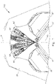
- FIG. 1 shows a flat knitting machine 100 with a front needle bed 10 and a rear needle bed 10' in cross section.
- a carriage 20 can be moved over the needle beds 10, 10', to which front and rear knitting cams 30, 30' are attached, with which knitting tools not shown here, which are mounted in the needle beds 10, 10', can be controlled and moved .
- the two needle beds enclose a comb gap KS between them. This is located on a central axis M of the flat knitting machine 100.
- Thread guides 40, 40' and 50, 50' are attached above the needle beds 10, 10' and the comb gap KS.
- the outer thread guides 40, 40' which are further away from the machine axis M, are conventional thread guides, which can be moved along with the carriage 20 via driver devices (not shown here).
- the inner thread guides 50, 50' are self-sufficiently driven thread guides, which can thus be moved by the carriage 20 independently. An up and down movement of the thread guide arm or the thread guide nut is also possible.
- the arrangement of the thread guides 40, 40' and 50, 50' in relation to the stitch axis M is merely an example.
- the thread guides 50, 50' could also be arranged on the outside or alternately with the thread guides 40, 40'.
- the thread guides 40, 40' and 50, 50' are also arranged on a circular arc around the comb gap. However, they could also be arranged in a common horizontal plane just above the comb gap, as later with reference to FIG 4 is made clear.
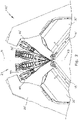
- FIG. 2 shows one of the 1 corresponding sectional view through a second flat knitting machine 100'.
- the machine 100' differs from the machine 100 in the design of the carriage 20' which, in contrast to the carriage 20, has an opening 21 on its upper side through which the threads are fed directly from above to the thread guides 40, 40', 50, 50' can become.
- a construction of the carriage 20' that is completely open at the top is also conceivable. Feeding the threads from above has the advantage that thread deflection devices, thread guide elements and thread tensioning elements can be dispensed with, which are necessary when the threads are fed to the thread guides 40, 40', 50, 50' from the side. Furthermore, the thread tension is reduced by reducing the friction points with such a thread feed.
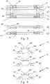
- FIGs 3a - 3d are different arrangements of the two types of yarn guides 40, 40 'and 50, 50' shown in yarn guide rails.
- Figure 3a a top view of four thread guide rails 61, 62, 63, 64 is shown, with thread guides 40, 40' that can be moved along with the carriage 20 being located exclusively in the thread guide rails 61 and 64. Separate thread guide rails 62, 63 are provided for the autonomous thread guides 50, 50'.
- the thread guides 40, 40' have recesses 41 on their upper side, into which driver devices (not shown) coupled to the carriage 20 can engage when the thread guides 40, 40' are to be moved.
- eight thread guides 40, 40' are arranged on the outer thread guide rails 61, 64, while only four independent thread guides 50, 50' are provided on the inner rails 62, 63.
- FIG. 3b Using the example of a single thread guide rail 60, FIG. On one of the halves of the thread guide rail 60 only thread guides 40 which can be moved along by the carriage are attached and on the other half only self-sufficient thread guides 50 are attached.
- a thread guide rail 60' is shown in which both thread guides 40 that can be moved by the carriage and autonomous thread guides 50 are arranged on one half, while thread guides 40 that can only be moved by the carriage are provided in the other half.
- a single thread guide rail 60" is shown, in which both thread guides 40, which can be moved by the carriage, and autonomous thread guides 50 are arranged on one half.
- the thread guides of the two drive concepts are mounted one above the other here. The principle can be used on one or both halves of the thread guide rail .
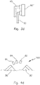
- Figures 4a - 4d show schematically different possibilities for the arrangement of the yarn guide rails above the carriage 20 with the knitting cams 30, 30' of the flat knitting machine 100.
- the rails are arranged on an imaginary cylinder surface, so that the thread guides (not shown) located therein 1 shown, take the central axis M toward inclined position.
- the rails 61' to 64' are all arranged in a common horizontal plane.
- Figure 4c shows a combination of the arrangements from the Figures 4a and 4b .
- the inner thread guide rails 62", 63" are arranged in a common horizontal plane and the outer thread guide rails 61" and 64" are arranged on an imaginary cylindrical surface.
- the rails are arranged asymmetrically on an imaginary cylinder surface, so that the thread guides (not shown) located therein also have the 1 shown, take the central axis M toward inclined position.
- Other variants of the asymmetrical arrangement of the yarn guide rails in terms of their number and in the Figures 4a - 4c arrangements shown are possible.
Description
Die Erfindung betrifft eine Flachstrickmaschine mit mindestens zwei Nadelbetten, mit mindestens einem über die Nadelbetten hinweg bewegbaren, mit Strickschlössern besetzten Schlitten und einer Fadenzuführvorrichtung mit oberhalb der Nadelbetten angeordneten Fadenführerschienen, in denen durch den mindestens einen Schlitten mitbewegbare Fadenführer angeordnet sind.The invention relates to a flat knitting machine with at least two needle beds, with at least one carriage equipped with knitting cams that can be moved over the needle beds, and a thread feed device with thread guide rails arranged above the needle beds, in which thread guides are arranged that can be moved by the at least one carriage.
Solche Flachstrickmaschinen entsprechen dem seit vielen Jahren üblichen Stand der Technik. Zunehmend werden jedoch immer höhere Ansprüche an die Musterung und das Design von Gestrickstücken gestellt. Damit steigen auch die Anforderungen an die Maschinen zur Herstellung solcher Gestricke, insbesondere von Intarsia-Gestricken oder von plattierten Gestricken.Such flat knitting machines correspond to the state of the art that has been common for many years. However, ever higher demands are being placed on the pattern and design of knitted fabrics. This also increases the demands on the machines for producing such knitted fabrics, in particular intarsia knitted fabrics or plated knitted fabrics.
Es wurden daher auch schon Verbesserungen hinsichtlich der Fadenzufuhr vorgeschlagen, die helfen, die erhöhten Anforderungen zu befriedigen. So sind bereits autark angetriebene Fadenführer eingesetzt worden, die während des Strickprozesses jede beliebige Position im Nadelraum einer Strickmaschine einnehmen können. Weiter sind Vorrichtungen zur Fadeneinlage bekannt geworden, die oberhalb und separat von den eigentlichen Fadenführern den Stricknadeln Fäden zuführen können.Improvements in thread feed have therefore already been proposed, which help to meet the increased requirements. Self-sufficiently driven thread guides have already been used, which can take up any desired position in the needle space of a knitting machine during the knitting process. Devices for inserting threads have also become known, which can feed threads to the knitting needles above and separately from the actual thread guides.
Aus der
Die
Der vorliegenden Erfindung liegt die Aufgabe zugrunde, eine Flachstrickmaschine bereitzustellen, mit der konventionelle Gestricke und Gestricke mit aufwändigen Mustern oder plattierte Gestricke auf rationelle Weise hergestellt werden können.The object of the present invention is to provide a flat knitting machine with which conventional knitted fabrics and knitted fabrics with complex patterns or plated knitted fabrics can be produced in a rational manner.
Die Aufgabe wird gelöst durch eine Flachstrickmaschine mit den Merkmalen des Anspruchs 1.The object is achieved by a flat knitting machine with the features of claim 1.
Die erfindungsgemäße Flachstrickmaschine stellt somit eine Kombination aus einer konventionellen Fadenzufuhr, bei der die Fadenführer durch geeignete Mittel vom Schlitten mitgenommen werden, und schlittenunabhängig angetriebene Fadenführer bereit, wobei beide Konzepte der Fadenzufuhr ihre volle Funktionsfähigkeit behalten. Dies ist vorteilhaft gegenüber einigen der oben erwähnten Vorrichtungen zur Fadenzufuhr, die einen Kompromiss zwischen den beiden Arten der Fadenzufuhr darstellen.The flat knitting machine according to the invention thus provides a combination of a conventional thread feed, in which the thread guides are taken along by the carriage by suitable means, and thread guides driven independently of the carriage, with both thread feed concepts retaining their full functionality. This is advantageous over some of the thread feeding devices mentioned above which represent a compromise between the two types of thread feeding.
Die Vorteile einer solchen Kombination der Antriebskonzepte der Fadenführer in einer einzigen Maschine liegen darin, dass komplizierte Muster wie Intarsia- oder Plattiermuster mit den autarken Fadenführern wirtschaftlich produziert werden können, da diese Fadenführer jederzeit jede beliebige Position im Nadelraum einnehmen können, während Gestricke oder Gestrickabschnitte mit konventionellen Mustern mit den vom Schlitten angetriebenen Fadenführern rationell produziert werden können.The advantages of such a combination of thread guide drive concepts in a single machine are that complicated patterns such as intarsia or plating patterns can be produced economically with the self-sufficient thread guides, since these thread guides can take up any position in the needle space at any time, while knitted fabrics or knitted sections with conventional patterns can be efficiently produced with the thread guides driven by the carriage.
Zweckmäßigerweise kann dabei jeder autarke Fadenführer eine eigene Antriebsvorrichtung aufweisen, um die Variabilität der Fadenzufuhr voll ausschöpfen zu können. Es ist jedoch auch möglich, zwei oder mehrere autarke Fadenführer mit einer gemeinsamen Antriebsvorrichtung zu versehen.Each self-sufficient thread guide can expediently have its own drive device in order to be able to fully exploit the variability of the thread feed. However, it is also possible to provide two or more self-sufficient thread guides with a common drive device.
Bei einer ersten Variante der Erfindung sind der oder die autarken Fadenführer in einer oder mehreren separaten Fadenführerschienen längs verschiebbar angeordnet. Sie können in diesen Schienen über die gesamte Länge verschoben werden, ohne mögliche Kollisionen mit einem vom Schlitten mitbewegten Fadenführer berücksichtigen zu müssen.In a first variant of the invention, the autonomous thread guide or thread guides are arranged in one or more separate thread guide rails so that they can be displaced longitudinally. They can be moved in these rails over the entire length without having to take into account possible collisions with a yarn guide moved by the carriage.
Dabei sind die Fadenführerschienen mit vom Schlitten mitbewegbaren Fadenführern und die Fadenführerschienen mit autarken Fadenführern im Wechsel parallel zueinander oberhalb der Nadelbetten angeordnet sein, um für beide Fadenführerarten ähnliche Bedingungen für die Fadenzufuhr zu den Nadeln schaffen zu können.The thread guide rails with thread guides that can be moved along by the carriage and the thread guide rails with self-sufficient thread guides are arranged alternately parallel to one another above the needle beds in order to be able to create similar conditions for the thread feed to the needles for both thread guide types.
Bei einer bevorzugten Ausgestaltung der Flachstrickmaschine sind dabei in den Fadenführerschienen für autarke Fadenführer jeweils vier Fadenführer angeordnet.In a preferred embodiment of the flat knitting machine, four thread guides are arranged in each case in the thread guide rails for autonomous thread guides.
In den Fadenführerschienen für vom Schlitten mitbewegbaren Fadenführer können jeweils acht Fadenführer angeordnet sein.Eight thread guides can be arranged in the thread guide rails for thread guides that can be moved along with the carriage.
Mit dieser Anzahl von Fadenführern lassen sich auch vielfarbige Muster oder Muster mit unterschiedlichen Fadenqualitäten rationell fertigen.With this number of thread guides, multicolored patterns or patterns with different thread qualities can also be produced efficiently.
Bei einer alternativen Ausgestaltung der Flachstrickmaschine, sind die autarken Fadenführer und die vom Schlitten mitbewegbaren Fadenführer in gemeinsamen Fadenführerschienen angeordnet. Es sind dann weniger Schienen erforderlich als bei einer Ausgestaltung mit separaten Schienen für die autarken Fadenführer.In an alternative embodiment of the flat knitting machine, the autonomous thread guides and the thread guides that can be moved along with the carriage are arranged in common thread guide rails. Fewer rails are then required than in an embodiment with separate rails for the autonomous thread guides.
Die autarken Fadenführer und die vom Schlitten mitbewegbaren Fadenführer sind in zumindest einer der Hälften der Fadenführerschiene gemeinsam angeordnet.The autonomous thread guides and the thread guides that can be moved along with the carriage are arranged together in at least one of the halves of the thread guide rail.
Eine weitere Alternative besteht darin, dass zumindest eine Hälfte einer oder mehrerer Fadenführerschienen zwei übereinander angeordnete Spuren aufweist, wobei in einer der Spuren ein oder mehrere autarke Fadenführer und in der anderen Spur ein oder mehrere vom Schlitten mitbewegte Fadenführer angeordnet sind. Dies hat den Vorteil, dass die Fadenführer beider Antriebskonzepte die vollständige Länge der Fadenführerschiene ausnutzen können.A further alternative is that at least one half of one or more thread guide rails has two tracks arranged one above the other, with one or more autonomous thread guides being arranged in one of the tracks and one or more thread guides moved by the carriage being arranged in the other track. This has the advantage that the thread guides of both Drive concepts can utilize the full length of the yarn guide rail.
Auch für die Anordnung der Fadenführerschienen oberhalb der Nadelbetten gibt es verschiedene Möglichkeiten. Bei einer ersten Ausgestaltung sind die Fadenführerschienen zumindest teilweise in einer gemeinsamen horizontalen Ebene oberhalb der Nadelbetten angeordnet. Es kann jedoch auch von Vorteil sein, die Fadenführerschienen zumindest teilweise auf einem Ausschnitt einer gedachten Zylinderoberfläche oberhalb der Nadelbetten anzuordnen. Die Fadenführerarme sind bei einer solchen Anordnung der Schienen radial ausgerichtet und besitzen alle dieselbe Form und Länge, was einen einfacheren Austausch ermöglicht und eine zeit- und kostengünstigere Fertigung erlaubt.There are also various options for arranging the thread guide rails above the needle beds. In a first embodiment, the thread guide rails are at least partially arranged in a common horizontal plane above the needle beds. However, it can also be advantageous to arrange the thread guide rails at least partially on a section of an imaginary cylinder surface above the needle beds. With such an arrangement of the rails, the yarn guide arms are aligned radially and all have the same shape and length, which enables simpler replacement and allows production to be made more quickly and cost-effectively.
Die beschriebenen Anordnungen der Fadenführerschienen müssen nicht zwangsläufig symmetrisch zur Mittelachse der Strickmaschine sein. Auch asymmetrische Anordnungen sind denkbar.The arrangements of the yarn guide rails described do not necessarily have to be symmetrical to the central axis of the knitting machine. Asymmetric arrangements are also conceivable.
Bei der erfindungsgemäßen Flachstrickmaschine können die Fäden wie allgemein üblich seitlich zugeführt werden. Die Flachstrickmaschine kann jedoch auch einen Schlitten aufweisen, der auf der Oberseite eine Öffnung aufweist, durch die Fäden zu den Fadenführern und weiter zu den Nadeln in den Nadelbetten zuführbar sind. Bei dieser Lösung kann auf eine ganze Reihe von Fadenleit- und Fadenspannelementen verzichtet werden, die bei einer seitlichen Zuführung der Fäden erforderlich sind. Ferner wird durch die Verringerung der Reibstellen bei einer solchen Fadenzufuhr die Fadenspannung reduziert.In the flat knitting machine according to the invention, the threads can be fed in from the side, as is generally customary. However, the flat knitting machine can also have a carriage which has an opening on the upper side through which threads can be fed to the thread guides and further to the needles in the needle beds. With this solution, a whole series of thread guide and thread tensioning elements, which are necessary when the threads are fed in from the side, can be dispensed with. Furthermore, the thread tension is reduced by reducing the friction points with such a thread feed.
Nachfolgend werden verschiedene Ausführungsbeispiele der Fadenzuführung von erfindungsgemäßen Flachstrickmaschinen mit Bezug auf die Zeichnung näher beschrieben.Various exemplary embodiments of the thread feed of flat knitting machines according to the invention are described in more detail below with reference to the drawing.
Es zeigen:
-
Fig. 1 einen Querschnitt durch eine erste Flachstrickmaschine; -
Fig. 2 einen Querschnitt durch eine zweite Flachstrickmaschine; -
Fig. 3a eine schematische Ansicht auf Fadenführerschienen für autarke Fadenführer und für vom Schlitten mitbewegte Fadenführer; -
Fig. 3b eine schematische Ansicht einer nicht erfindungsgemäßen ersten Fadenführerschiene mit autarken und vom Schlitten mitbewegbaren Fadenführern; -
Fig. 3c eine schematische Ansicht einer zweiten Fadenführerschiene mit autarken und vom Schlitten mitbewegbaren Fadenführern; -
Fig. 3d eine schematische Ansicht einer dritten Fadenführerschiene mit autarken und vom Schlitten mitbewegbaren Fadenführern; -
Fig. 4a - 4d schematische Darstellungen unterschiedlicher Anordnungen von Fadenführerschienen in einer Flachstrickmaschine.
-
1 a cross section through a first flat knitting machine; -
2 a cross section through a second flat knitting machine; -
Figure 3a a schematic view of yarn guide rails for self-sufficient yarn guides and for yarn guides moved along by the carriage; -
Figure 3b a schematic view of a non-inventive first thread guide rail with self-sufficient thread guides that can be moved along with the carriage; -
3c a schematic view of a second yarn guide rail with autonomous yarn guides that can be moved along with the carriage; -
3d a schematic view of a third thread guide rail with self-sufficient thread guides that can be moved along with the carriage; -
Figures 4a - 4d Schematic representations of different arrangements of thread guide rails in a flat knitting machine.
Oberhalb der Nadelbetten 10, 10' und des Kammspaltes KS sind Fadenführer 40, 40' und 50, 50' angebracht. Die äußeren, von der Maschinenachse M weiter entfernten Fadenführer 40, 40' sind konventionelle Fadenführer, die vom Schlitten 20 über hier nicht gezeigte Mitnehmereinrichtungen mitbewegbar sind. Die inneren Fadenführer 50, 50' sind dagegen autark angetrieben Fadenführer, die somit vom Schlitten 20 unabhängig bewegt werden können. Auch eine Auf- und Abbewegung des Fadenführerarms bzw. des Fadenführernüsschens ist möglich. Die Anordnung der Fadenführer 40, 40' und 50, 50' in Bezug auf die Maschenachse M ist lediglich beispielhaft. Die Fadenführer 50, 50' könnten auch außen oder im Wechsel mit den Fadenführern 40, 40' angeordnet sein. Im dargestellten Beispiel sind die Fadenführer 40, 40' und 50, 50' außerdem auf einem Kreisbogen um den Kammspalt angeordnet. Sie könnten jedoch auch in einer gemeinsamen Horizontalen eben über dem Kammspalt angeordnet sein, wie später mit Bezug auf
In den
Die Fadenführer 40, 40' weisen an ihrer Oberseite Ausnehmungen 41 auf, in die nicht weiter dargestellte, mit dem Schlitten 20 gekoppelte Mitnahmeeinrichtungen eingreifen können, wenn die Fadenführer 40, 40' bewegt werden sollen.The thread guides 40, 40' have
Im dargestellten Beispiel sind auf den äußeren Fadenführerschienen 61, 64 jeweils acht Fadenführer 40, 40' angeordnet, während auf den inneren Schienen 62, 63 jeweils nur vier autarke Fadenführer 50, 50' vorgesehen sind.In the example shown, eight thread guides 40, 40' are arranged on the outer
In
In
Die
In
In
Claims (6)
- Flat knitting machine with at least two needle beds (30, 30'), at least one carriage (20) movable over the needle beds (10, 10') and equipped with knitting cams (30, 30'), and a yarn infeed device with yarn guide rails (60, 60', 61-64) arranged above the needle beds, wherein yarn guides (40, 40'), movable with the carriage (20), are arranged in said rails, wherein the yarn infeed device also has at least one autonomous yarn guide (50, 50') driven independently of carriage (20), whereina) the at least one autonomous yarn guide (50, 50') is arranged to be movable longitudinally in one or more separate yarn guide rails (62, 63 and the yarn guide rails (61, 64) with yarn guides (40, 40') movable by the carriage and the yarn guide rails (62, 63) with autonomous yarn guides (50, 50') are arranged alternately parallel to each other above the needle beds (10, 10') orb) the autonomous yarn guides (50, 50') and the yarn guides (40, 40'), movable by the carriage (20), are arranged in common yarn guide rails (60, 60') and the autonomous yarn guides (50, 50') and the yarn guides (40, 40') movable by carriage (20) are jointly arranged in at least one of the halves of the yarn guide rail (60').
- Flat knitting machine according to claim 1, characterised in that each autonomous yarn guide (50, 50') has its own drive device.
- Flat knitting machine according to any of the preceding claims in connection with variant b) of claim 1, characterised in that at least one half of one or more yarn guide rails has two tracks arranged one over the other, wherein, in one of the tracks, one or more autonomous yarn guides and in the other track, one or more yarn guides movable by the carriage are arranged.
- Flat knitting machine according to any one of the preceding claims, characterised in that the yarn guide rails (61' - 64', 62", 63") are arranged at least partly in a common horizontal plane above the needle beds (10, 10').
- Flat knitting machine according to any one of the preceding claims, characterised in that the yarn guide rails (61 - 64, 61", 64") are arranged at least partly on a section of an imaginary cylindrical surface above the needle beds (10, 10').
- Flat knitting machine according to any one of the preceding claims, characterised in that the carriages (20) have an opening (21) an the upper side, through which yarn can be fed from above to the yarn guides (40, 40', 50, 50') and then to needles in the needle beds.
Priority Applications (2)
| Application Number | Priority Date | Filing Date | Title |
|---|---|---|---|
| EP15176118.6A EP3115491B2 (en) | 2015-07-09 | 2015-07-09 | Flat knitting machine |
| CN201610534695.0A CN106337248B (en) | 2015-07-09 | 2016-07-08 | flat knitting machine |
Applications Claiming Priority (1)
| Application Number | Priority Date | Filing Date | Title |
|---|---|---|---|
| EP15176118.6A EP3115491B2 (en) | 2015-07-09 | 2015-07-09 | Flat knitting machine |
Publications (4)
| Publication Number | Publication Date |
|---|---|
| EP3115491A1 EP3115491A1 (en) | 2017-01-11 |
| EP3115491B1 EP3115491B1 (en) | 2018-12-19 |
| EP3115491B8 EP3115491B8 (en) | 2019-03-20 |
| EP3115491B2 true EP3115491B2 (en) | 2022-08-03 |
Family
ID=53541550
Family Applications (1)
| Application Number | Title | Priority Date | Filing Date |
|---|---|---|---|
| EP15176118.6A Active EP3115491B2 (en) | 2015-07-09 | 2015-07-09 | Flat knitting machine |
Country Status (2)
| Country | Link |
|---|---|
| EP (1) | EP3115491B2 (en) |
| CN (1) | CN106337248B (en) |
Families Citing this family (4)
| Publication number | Priority date | Publication date | Assignee | Title |
|---|---|---|---|---|
| EP3556921B1 (en) | 2018-04-16 | 2021-09-01 | KARL MAYER STOLL R&D GmbH | Flat knitting machine and method for producing a filigrane knit |
| JP7296707B2 (en) | 2018-10-12 | 2023-06-23 | 株式会社島精機製作所 | Yarn feeding device |
| EP4019682B1 (en) * | 2020-12-23 | 2023-08-30 | KARL MAYER STOLL R&D GmbH | Knitting machine with at least one yarn guide |
| EP4019683A1 (en) * | 2020-12-23 | 2022-06-29 | KARL MAYER STOLL R&D GmbH | Knitting machine with at least one yarn guide for feeding one or more separate yarns |
Citations (1)
| Publication number | Priority date | Publication date | Assignee | Title |
|---|---|---|---|---|
| EP0898002B1 (en) † | 1997-08-21 | 2003-03-26 | Shima Seiki Manufacturing, Ltd. | A flat knitting machine having a yarn feeding system |
Family Cites Families (8)
| Publication number | Priority date | Publication date | Assignee | Title |
|---|---|---|---|---|
| CH686089A5 (en) | 1991-08-02 | 1995-12-29 | Steiger Sa Atelier Constr | Flatbed knitting machine. |
| DE4308251C2 (en) | 1992-03-17 | 1997-10-09 | Schieber Universal Maschf | Knitting machine |
| US5623840A (en) | 1992-07-08 | 1997-04-29 | Tecnit-Technische Textilien Und Systeme Gmbh | Process for production of weave-knit material |
| JP3452639B2 (en) | 1994-05-02 | 2003-09-29 | 株式会社島精機製作所 | Knitting yarn supply device to flat knitting machine |
| JPH08127948A (en) | 1994-10-31 | 1996-05-21 | Shima Seiki Mfg Ltd | Method for controlling carrier of knitting machine and apparatus therefor |
| JP2903152B2 (en) | 1997-04-15 | 1999-06-07 | 株式会社島精機製作所 | Yarn supply mechanism of flat knitting machine |
| CN2749896Y (en) * | 2004-10-21 | 2006-01-04 | 东华大学 | Flat-knitting machine yarn feeding device special for multi-axial reinforced framework knitting structure |
| DE102009032627B4 (en) * | 2009-07-10 | 2012-10-18 | H. Stoll Gmbh & Co. Kg | Flat knitting machine with coupled with a drive means yarn guides |
-
2015
- 2015-07-09 EP EP15176118.6A patent/EP3115491B2/en active Active
-
2016
- 2016-07-08 CN CN201610534695.0A patent/CN106337248B/en active Active
Patent Citations (1)
| Publication number | Priority date | Publication date | Assignee | Title |
|---|---|---|---|---|
| EP0898002B1 (en) † | 1997-08-21 | 2003-03-26 | Shima Seiki Manufacturing, Ltd. | A flat knitting machine having a yarn feeding system |
Non-Patent Citations (2)
| Title |
|---|
| KEN MYOHDAI: "Neue Intarsien-Strickmaschine Modell INS-40", WIRKEREI- UND STRICKEREI-TECHNIK, vol. 40, no. 5, 1990, pages 482 - 484 † |
| MITSUBOSHI: "Computerized Intarsia Flat Knitting Machine Model INS-40", MITSUBOSHI - LEAFLET, 11 July 1990 (1990-07-11), pages 1 - 6 † |
Also Published As
| Publication number | Publication date |
|---|---|
| CN106337248B (en) | 2019-01-04 |
| CN106337248A (en) | 2017-01-18 |
| EP3115491B1 (en) | 2018-12-19 |
| EP3115491B8 (en) | 2019-03-20 |
| EP3115491A1 (en) | 2017-01-11 |
Similar Documents
| Publication | Publication Date | Title |
|---|---|---|
| DE4222792B4 (en) | Thread guide actuating device in a flat knitting machine | |
| EP3115491B2 (en) | Flat knitting machine | |
| EP3307934B1 (en) | Braiding machine | |
| DE3311361C2 (en) | Knitting machine for the production of knitted fabrics | |
| DE102009032627B4 (en) | Flat knitting machine with coupled with a drive means yarn guides | |
| DE19707053A1 (en) | High / low plush knitwear and method and device for its manufacture | |
| EP0531789A1 (en) | Circular knitting machine for producing plush articles | |
| EP0338194B1 (en) | Method for manufacturing intarsia knitwear, and flat-bed knitting machine for carrying out this method | |
| DE3532943C2 (en) | ||
| EP2302118B1 (en) | Method and knitting machine for producing knitted goods with stripe patterns | |
| EP0139926B1 (en) | Straight bar knitting machine (cotton system) | |
| EP1167602B1 (en) | Flat bed knitting machine | |
| EP3307933B1 (en) | Braiding machine | |
| DE3033102C2 (en) | ||
| DE19505646A1 (en) | Pile fabric knitting | |
| DE102010017946B4 (en) | Lock system for a flat knitting machine | |
| EP2078773B1 (en) | Cartridge of a knitting machine | |
| DE3814881C2 (en) | Multi-system circular knitting machine | |
| EP2570536B1 (en) | Flat knitting machine | |
| CH632023A5 (en) | METHOD FOR MACHINE KNITTING A ONE-PIECE CLOTHING PIECE. | |
| EP4019680B1 (en) | Knitting system for a flat knitting machine, flat knitting machine compising the same and method for operating said knitting machine | |
| DE3506558A1 (en) | Needle-selection device for knitting machines | |
| EP4019682B1 (en) | Knitting machine with at least one yarn guide | |
| DE1585498B1 (en) | System Cotton flat weft knitting machine | |
| EP2570538B1 (en) | Thread guide for a flat knitting machine |
Legal Events
| Date | Code | Title | Description |
|---|---|---|---|
| PUAI | Public reference made under article 153(3) epc to a published international application that has entered the european phase |
Free format text: ORIGINAL CODE: 0009012 |
|
| STAA | Information on the status of an ep patent application or granted ep patent |
Free format text: STATUS: THE APPLICATION HAS BEEN PUBLISHED |
|
| AK | Designated contracting states |
Kind code of ref document: A1 Designated state(s): AL AT BE BG CH CY CZ DE DK EE ES FI FR GB GR HR HU IE IS IT LI LT LU LV MC MK MT NL NO PL PT RO RS SE SI SK SM TR |
|
| AX | Request for extension of the european patent |
Extension state: BA ME |
|
| STAA | Information on the status of an ep patent application or granted ep patent |
Free format text: STATUS: REQUEST FOR EXAMINATION WAS MADE |
|
| 17P | Request for examination filed |
Effective date: 20170628 |
|
| RBV | Designated contracting states (corrected) |
Designated state(s): AL AT BE BG CH CY CZ DE DK EE ES FI FR GB GR HR HU IE IS IT LI LT LU LV MC MK MT NL NO PL PT RO RS SE SI SK SM TR |
|
| GRAJ | Information related to disapproval of communication of intention to grant by the applicant or resumption of examination proceedings by the epo deleted |
Free format text: ORIGINAL CODE: EPIDOSDIGR1 |
|
| GRAP | Despatch of communication of intention to grant a patent |
Free format text: ORIGINAL CODE: EPIDOSNIGR1 |
|
| RIC1 | Information provided on ipc code assigned before grant |
Ipc: D04B 15/56 20060101AFI20180626BHEP Ipc: D04B 15/96 20060101ALI20180626BHEP |
|
| GRAP | Despatch of communication of intention to grant a patent |
Free format text: ORIGINAL CODE: EPIDOSNIGR1 |
|
| STAA | Information on the status of an ep patent application or granted ep patent |
Free format text: STATUS: GRANT OF PATENT IS INTENDED |
|
| INTG | Intention to grant announced |
Effective date: 20180808 |
|
| GRAS | Grant fee paid |
Free format text: ORIGINAL CODE: EPIDOSNIGR3 |
|
| GRAA | (expected) grant |
Free format text: ORIGINAL CODE: 0009210 |
|
| STAA | Information on the status of an ep patent application or granted ep patent |
Free format text: STATUS: THE PATENT HAS BEEN GRANTED |
|
| AK | Designated contracting states |
Kind code of ref document: B1 Designated state(s): AL AT BE BG CH CY CZ DE DK EE ES FI FR GB GR HR HU IE IS IT LI LT LU LV MC MK MT NL NO PL PT RO RS SE SI SK SM TR |
|
| REG | Reference to a national code |
Ref country code: GB Ref legal event code: FG4D Free format text: NOT ENGLISH |
|
| REG | Reference to a national code |
Ref country code: CH Ref legal event code: EP |
|
| REG | Reference to a national code |
Ref country code: IE Ref legal event code: FG4D Free format text: LANGUAGE OF EP DOCUMENT: GERMAN |
|
| REG | Reference to a national code |
Ref country code: DE Ref legal event code: R096 Ref document number: 502015007302 Country of ref document: DE |
|
| REG | Reference to a national code |
Ref country code: DE Ref legal event code: R081 Ref document number: 502015007302 Country of ref document: DE Owner name: KARL MAYER STOLL R&D GMBH, DE Free format text: FORMER OWNER: H. STOLL GMBH & CO. KG, 72760 REUTLINGEN, DE Ref country code: AT Ref legal event code: REF Ref document number: 1078830 Country of ref document: AT Kind code of ref document: T Effective date: 20190115 Ref country code: DE Ref legal event code: R081 Ref document number: 502015007302 Country of ref document: DE Owner name: H. STOLL AG & CO. KG, DE Free format text: FORMER OWNER: H. STOLL GMBH & CO. KG, 72760 REUTLINGEN, DE |
|
| GRAT | Correction requested after decision to grant or after decision to maintain patent in amended form |
Free format text: ORIGINAL CODE: EPIDOSNCDEC |
|
| RAP2 | Party data changed (patent owner data changed or rights of a patent transferred) |
Owner name: H. STOLL AG & CO. KG |
|
| REG | Reference to a national code |
Ref country code: CH Ref legal event code: PK Free format text: BERICHTIGUNG B8 |
|
| REG | Reference to a national code |
Ref country code: AT Ref legal event code: HC Ref document number: 1078830 Country of ref document: AT Kind code of ref document: T Owner name: H. STOLL AG & CO. KG, DE Effective date: 20190213 |
|
| REG | Reference to a national code |
Ref country code: NL Ref legal event code: MP Effective date: 20181219 |
|
| PG25 | Lapsed in a contracting state [announced via postgrant information from national office to epo] |
Ref country code: FI Free format text: LAPSE BECAUSE OF FAILURE TO SUBMIT A TRANSLATION OF THE DESCRIPTION OR TO PAY THE FEE WITHIN THE PRESCRIBED TIME-LIMIT Effective date: 20181219 Ref country code: LV Free format text: LAPSE BECAUSE OF FAILURE TO SUBMIT A TRANSLATION OF THE DESCRIPTION OR TO PAY THE FEE WITHIN THE PRESCRIBED TIME-LIMIT Effective date: 20181219 Ref country code: LT Free format text: LAPSE BECAUSE OF FAILURE TO SUBMIT A TRANSLATION OF THE DESCRIPTION OR TO PAY THE FEE WITHIN THE PRESCRIBED TIME-LIMIT Effective date: 20181219 Ref country code: HR Free format text: LAPSE BECAUSE OF FAILURE TO SUBMIT A TRANSLATION OF THE DESCRIPTION OR TO PAY THE FEE WITHIN THE PRESCRIBED TIME-LIMIT Effective date: 20181219 Ref country code: BG Free format text: LAPSE BECAUSE OF FAILURE TO SUBMIT A TRANSLATION OF THE DESCRIPTION OR TO PAY THE FEE WITHIN THE PRESCRIBED TIME-LIMIT Effective date: 20190319 Ref country code: NO Free format text: LAPSE BECAUSE OF FAILURE TO SUBMIT A TRANSLATION OF THE DESCRIPTION OR TO PAY THE FEE WITHIN THE PRESCRIBED TIME-LIMIT Effective date: 20190319 |
|
| REG | Reference to a national code |
Ref country code: LT Ref legal event code: MG4D |
|
| PG25 | Lapsed in a contracting state [announced via postgrant information from national office to epo] |
Ref country code: RS Free format text: LAPSE BECAUSE OF FAILURE TO SUBMIT A TRANSLATION OF THE DESCRIPTION OR TO PAY THE FEE WITHIN THE PRESCRIBED TIME-LIMIT Effective date: 20181219 Ref country code: GR Free format text: LAPSE BECAUSE OF FAILURE TO SUBMIT A TRANSLATION OF THE DESCRIPTION OR TO PAY THE FEE WITHIN THE PRESCRIBED TIME-LIMIT Effective date: 20190320 Ref country code: AL Free format text: LAPSE BECAUSE OF FAILURE TO SUBMIT A TRANSLATION OF THE DESCRIPTION OR TO PAY THE FEE WITHIN THE PRESCRIBED TIME-LIMIT Effective date: 20181219 Ref country code: SE Free format text: LAPSE BECAUSE OF FAILURE TO SUBMIT A TRANSLATION OF THE DESCRIPTION OR TO PAY THE FEE WITHIN THE PRESCRIBED TIME-LIMIT Effective date: 20181219 |
|
| PG25 | Lapsed in a contracting state [announced via postgrant information from national office to epo] |
Ref country code: NL Free format text: LAPSE BECAUSE OF FAILURE TO SUBMIT A TRANSLATION OF THE DESCRIPTION OR TO PAY THE FEE WITHIN THE PRESCRIBED TIME-LIMIT Effective date: 20181219 |
|
| PG25 | Lapsed in a contracting state [announced via postgrant information from national office to epo] |
Ref country code: PT Free format text: LAPSE BECAUSE OF FAILURE TO SUBMIT A TRANSLATION OF THE DESCRIPTION OR TO PAY THE FEE WITHIN THE PRESCRIBED TIME-LIMIT Effective date: 20190419 Ref country code: ES Free format text: LAPSE BECAUSE OF FAILURE TO SUBMIT A TRANSLATION OF THE DESCRIPTION OR TO PAY THE FEE WITHIN THE PRESCRIBED TIME-LIMIT Effective date: 20181219 Ref country code: CZ Free format text: LAPSE BECAUSE OF FAILURE TO SUBMIT A TRANSLATION OF THE DESCRIPTION OR TO PAY THE FEE WITHIN THE PRESCRIBED TIME-LIMIT Effective date: 20181219 Ref country code: PL Free format text: LAPSE BECAUSE OF FAILURE TO SUBMIT A TRANSLATION OF THE DESCRIPTION OR TO PAY THE FEE WITHIN THE PRESCRIBED TIME-LIMIT Effective date: 20181219 |
|
| PG25 | Lapsed in a contracting state [announced via postgrant information from national office to epo] |
Ref country code: EE Free format text: LAPSE BECAUSE OF FAILURE TO SUBMIT A TRANSLATION OF THE DESCRIPTION OR TO PAY THE FEE WITHIN THE PRESCRIBED TIME-LIMIT Effective date: 20181219 Ref country code: SM Free format text: LAPSE BECAUSE OF FAILURE TO SUBMIT A TRANSLATION OF THE DESCRIPTION OR TO PAY THE FEE WITHIN THE PRESCRIBED TIME-LIMIT Effective date: 20181219 Ref country code: SK Free format text: LAPSE BECAUSE OF FAILURE TO SUBMIT A TRANSLATION OF THE DESCRIPTION OR TO PAY THE FEE WITHIN THE PRESCRIBED TIME-LIMIT Effective date: 20181219 Ref country code: RO Free format text: LAPSE BECAUSE OF FAILURE TO SUBMIT A TRANSLATION OF THE DESCRIPTION OR TO PAY THE FEE WITHIN THE PRESCRIBED TIME-LIMIT Effective date: 20181219 Ref country code: IS Free format text: LAPSE BECAUSE OF FAILURE TO SUBMIT A TRANSLATION OF THE DESCRIPTION OR TO PAY THE FEE WITHIN THE PRESCRIBED TIME-LIMIT Effective date: 20190419 |
|
| REG | Reference to a national code |
Ref country code: DE Ref legal event code: R026 Ref document number: 502015007302 Country of ref document: DE |
|
| PLBI | Opposition filed |
Free format text: ORIGINAL CODE: 0009260 |
|
| 26 | Opposition filed |
Opponent name: SHIMA SEIKI MANUFACTURING, LTD. Effective date: 20190918 |
|
| PG25 | Lapsed in a contracting state [announced via postgrant information from national office to epo] |
Ref country code: DK Free format text: LAPSE BECAUSE OF FAILURE TO SUBMIT A TRANSLATION OF THE DESCRIPTION OR TO PAY THE FEE WITHIN THE PRESCRIBED TIME-LIMIT Effective date: 20181219 |
|
| PLAX | Notice of opposition and request to file observation + time limit sent |
Free format text: ORIGINAL CODE: EPIDOSNOBS2 |
|
| PG25 | Lapsed in a contracting state [announced via postgrant information from national office to epo] |
Ref country code: SI Free format text: LAPSE BECAUSE OF FAILURE TO SUBMIT A TRANSLATION OF THE DESCRIPTION OR TO PAY THE FEE WITHIN THE PRESCRIBED TIME-LIMIT Effective date: 20181219 Ref country code: MC Free format text: LAPSE BECAUSE OF FAILURE TO SUBMIT A TRANSLATION OF THE DESCRIPTION OR TO PAY THE FEE WITHIN THE PRESCRIBED TIME-LIMIT Effective date: 20181219 |
|
| REG | Reference to a national code |
Ref country code: CH Ref legal event code: PL |
|
| GBPC | Gb: european patent ceased through non-payment of renewal fee |
Effective date: 20190709 |
|
| REG | Reference to a national code |
Ref country code: BE Ref legal event code: MM Effective date: 20190731 |
|
| PG25 | Lapsed in a contracting state [announced via postgrant information from national office to epo] |
Ref country code: GB Free format text: LAPSE BECAUSE OF NON-PAYMENT OF DUE FEES Effective date: 20190709 |
|
| PLAF | Information modified related to communication of a notice of opposition and request to file observations + time limit |
Free format text: ORIGINAL CODE: EPIDOSCOBS2 |
|
| PG25 | Lapsed in a contracting state [announced via postgrant information from national office to epo] |
Ref country code: LI Free format text: LAPSE BECAUSE OF NON-PAYMENT OF DUE FEES Effective date: 20190731 Ref country code: BE Free format text: LAPSE BECAUSE OF NON-PAYMENT OF DUE FEES Effective date: 20190731 Ref country code: CH Free format text: LAPSE BECAUSE OF NON-PAYMENT OF DUE FEES Effective date: 20190731 Ref country code: LU Free format text: LAPSE BECAUSE OF NON-PAYMENT OF DUE FEES Effective date: 20190709 |
|
| PG25 | Lapsed in a contracting state [announced via postgrant information from national office to epo] |
Ref country code: FR Free format text: LAPSE BECAUSE OF NON-PAYMENT OF DUE FEES Effective date: 20190731 |
|
| PLBB | Reply of patent proprietor to notice(s) of opposition received |
Free format text: ORIGINAL CODE: EPIDOSNOBS3 |
|
| PG25 | Lapsed in a contracting state [announced via postgrant information from national office to epo] |
Ref country code: IE Free format text: LAPSE BECAUSE OF NON-PAYMENT OF DUE FEES Effective date: 20190709 |
|
| PG25 | Lapsed in a contracting state [announced via postgrant information from national office to epo] |
Ref country code: CY Free format text: LAPSE BECAUSE OF FAILURE TO SUBMIT A TRANSLATION OF THE DESCRIPTION OR TO PAY THE FEE WITHIN THE PRESCRIBED TIME-LIMIT Effective date: 20181219 |
|
| REG | Reference to a national code |
Ref country code: DE Ref legal event code: R082 Ref document number: 502015007302 Country of ref document: DE Representative=s name: KOHLER SCHMID MOEBUS PATENTANWAELTE PARTNERSCH, DE Ref country code: DE Ref legal event code: R081 Ref document number: 502015007302 Country of ref document: DE Owner name: KARL MAYER STOLL R&D GMBH, DE Free format text: FORMER OWNER: H. STOLL AG & CO. KG, 72760 REUTLINGEN, DE |
|
| PG25 | Lapsed in a contracting state [announced via postgrant information from national office to epo] |
Ref country code: MT Free format text: LAPSE BECAUSE OF FAILURE TO SUBMIT A TRANSLATION OF THE DESCRIPTION OR TO PAY THE FEE WITHIN THE PRESCRIBED TIME-LIMIT Effective date: 20181219 Ref country code: HU Free format text: LAPSE BECAUSE OF FAILURE TO SUBMIT A TRANSLATION OF THE DESCRIPTION OR TO PAY THE FEE WITHIN THE PRESCRIBED TIME-LIMIT; INVALID AB INITIO Effective date: 20150709 |
|
| REG | Reference to a national code |
Ref country code: AT Ref legal event code: MM01 Ref document number: 1078830 Country of ref document: AT Kind code of ref document: T Effective date: 20200709 |
|
| PG25 | Lapsed in a contracting state [announced via postgrant information from national office to epo] |
Ref country code: AT Free format text: LAPSE BECAUSE OF NON-PAYMENT OF DUE FEES Effective date: 20200709 |
|
| PG25 | Lapsed in a contracting state [announced via postgrant information from national office to epo] |
Ref country code: MK Free format text: LAPSE BECAUSE OF FAILURE TO SUBMIT A TRANSLATION OF THE DESCRIPTION OR TO PAY THE FEE WITHIN THE PRESCRIBED TIME-LIMIT Effective date: 20181219 |
|
| PUAH | Patent maintained in amended form |
Free format text: ORIGINAL CODE: 0009272 |
|
| STAA | Information on the status of an ep patent application or granted ep patent |
Free format text: STATUS: PATENT MAINTAINED AS AMENDED |
|
| 27A | Patent maintained in amended form |
Effective date: 20220803 |
|
| AK | Designated contracting states |
Kind code of ref document: B2 Designated state(s): AL AT BE BG CH CY CZ DE DK EE ES FI FR GB GR HR HU IE IS IT LI LT LU LV MC MK MT NL NO PL PT RO RS SE SI SK SM TR |
|
| REG | Reference to a national code |
Ref country code: DE Ref legal event code: R102 Ref document number: 502015007302 Country of ref document: DE |
|
| P01 | Opt-out of the competence of the unified patent court (upc) registered |
Effective date: 20230630 |
|
| PGFP | Annual fee paid to national office [announced via postgrant information from national office to epo] |
Ref country code: TR Payment date: 20230705 Year of fee payment: 9 Ref country code: IT Payment date: 20230731 Year of fee payment: 9 |
|
| PGFP | Annual fee paid to national office [announced via postgrant information from national office to epo] |
Ref country code: DE Payment date: 20230726 Year of fee payment: 9 |