EP2078773B1 - Cartridge of a knitting machine - Google Patents
Cartridge of a knitting machine Download PDFInfo
- Publication number
- EP2078773B1 EP2078773B1 EP20080000532 EP08000532A EP2078773B1 EP 2078773 B1 EP2078773 B1 EP 2078773B1 EP 20080000532 EP20080000532 EP 20080000532 EP 08000532 A EP08000532 A EP 08000532A EP 2078773 B1 EP2078773 B1 EP 2078773B1
- Authority
- EP
- European Patent Office
- Prior art keywords
- cassette
- needle bed
- cassettes
- knitting machine
- stitch
- Prior art date
- Legal status (The legal status is an assumption and is not a legal conclusion. Google has not performed a legal analysis and makes no representation as to the accuracy of the status listed.)
- Active
Links
Images


Classifications
-
- D—TEXTILES; PAPER
- D04—BRAIDING; LACE-MAKING; KNITTING; TRIMMINGS; NON-WOVEN FABRICS
- D04B—KNITTING
- D04B15/00—Details of, or auxiliary devices incorporated in, weft knitting machines, restricted to machines of this kind
- D04B15/06—Sinkers
-
- D—TEXTILES; PAPER
- D04—BRAIDING; LACE-MAKING; KNITTING; TRIMMINGS; NON-WOVEN FABRICS
- D04B—KNITTING
- D04B15/00—Details of, or auxiliary devices incorporated in, weft knitting machines, restricted to machines of this kind
- D04B15/10—Needle beds
Definitions
- the invention relates to a cassette which can be fastened to the needle bed of a knitting machine, and to a knitting machine with such a cassette.
- the Fig. 1a shows a section of the mesh image area of a needle bed 1 "according to the prior art in a view from above of the needle bed 1".
- the Fig. 1b shows the stitching area of the needle bed 1 "in a sectional view along the line AA Fig. 1a ,
- the needles 50 are guided in the groove 11".
- the mesh images 70 get their height fiung in the groove 13 "of the needle bed 1".
- the hold-down boards 80 are located in a similar position on the stitch-side longitudinal side of the needle bed 1 "as the stitches 70 and are therefore at risk of being damaged
- the stitches 70 and hold-down boards 80 are fixed in position in the needle bed 1" by the same round bar 60 .
- the round bar 60 forms the fixation of its position to the stitch-side longitudinal side of the needle bed 1 "and for the hold-down boards 80 additionally forms the axis about which the hold-down boards 80 make their pivotal movements must be and these are disadvantageously in the middle of the needle bed 1 ", the round rod 60 must be pulled laterally at least half its length from the needle bed 1" Also at least half its length must be the tee-off edge forming round wire 90 laterally from the needle bed 1 ", since it is circular-hole-shaped from the mesh images 70 and long hole-shaped from the hold-down plates 80.
- the round wire 90 has been given a kink by deformed stitch patterns 70 and therefore can not be pulled out through the holes of the stitch patterns 70 and hold down plates 80 in one direction. In this case, the round wire 90 must be severed before and after the kink so that it can be removed therefrom at both ends of the needle bed 1.
- Object of the present invention is therefore to remedy this situation and in particular to allow easier replacement of damaged elements of the stitch formation area.
- a cassette which is detachably fastened to the needle bed of a knitting machine and has at least one active element required for stitch formation.
- each knitting tool in particular each needle, a cassette assigned.
- the cassettes can be attached to the needle bed independently of a round bar or round wire.
- knitting elements needed for the stitch formation can be a stitch pattern and / or a knock-off edge.
- cassette is releasably attachable to the needle bed. This creates the opportunity to exchange individual cartridges that have damaged active elements. It is not necessary to first remove a round rod or round wire which is in contact with all the active elements before a damaged active element can be exchanged. The repair and repair of a knitting machine can thus be done much faster.
- the cassette can be locked on the needle bed.
- a locking connection By a locking connection, a particularly simple and reliable attachment to the needle bed can be made.
- a locking connection is usually easily solvable, so that a replacement of a cassette can be done quickly.
- the cassette can be attached to the needle bed without tools and / or can be detached from the needle bed. This also makes it possible to speed up the replacement of a cassette.
- the attachment or removal of the cassette on the needle bed can therefore be done without technical aids.
- the cassette has a stitch pattern and / or a knock-off edge. As a result, these elements do not have to be formed separately on the needle bed.
- the cassette has at least one knitting element which facilitates the stitch formation.
- the cassette may have a hold-down plate and / or a mesh wiper and / or a yarn feeder. It is also possible to store combinations of said elements in the cassettes.
- the cassette can have at least one side plate which comprises or is at least partially designed as an active element needed for stitch formation.
- two side plates may be provided which contain the active elements needed for stitch formation.
- a stitch pattern is formed on a first side panel and a knock-off edge on a second side panel. Between the side plates knitting elements can be arranged, which favor the stitch formation.
- a particularly simple embodiment of a knock-off edge is obtained when bolts are arranged on the side plates as a knock-off edge.
- a hold-down board may be arranged, which in turn is disposed on a slider which is movable relative to the side plates.
- a side plate has a portion with which it can be arranged in a guide of the needle bed.
- the cassette can be fixed in position to its correspondence needle in the needle bed.
- the cassette may have a spring leg with a notch.
- the spring leg with its notch may comprise a round rod which is mounted in a groove of the needle bed.
- a knitting machine with at least one needle bed and relative to the needle bed movable knitting tools, in particular needles, wherein each knitting tool is associated with a cassette according to the invention.
- damaged active elements can be exchanged particularly easily by exchanging the cassettes in which the active elements are arranged. The replacement of one cartridge can be done without any impact on another cartridge.
- the needle bed has guides for the cassettes. This defines the position of the cartridges.
- the guides for the cassettes and guides for the needles are parallel at least in a stitch formation area.
- recesses may be provided for impact noses arranged in the cassette hold-down.
- the recesses may be arranged perpendicular to a plane of the needle bed extending in the longitudinal direction of the needle bed. In this case, the front end of the cutout can be widened. In this widening, the cassette can be guided laterally in the area of the needle bed that is closest to the stitching.
- a height fixing stop for the cassettes can be provided at the needle bed.
- a stepped surface can be provided for this, which extends parallel to a plane in the longitudinal direction of the needle bed.
- the cassettes are locked on the needle bed. As a result, they can also be easily removed from the needle bed so that they can be replaced if necessary.
- cassettes are fixed by means of a wedge-shaped strip on the needle bed.
- a knock-off edge may be provided at the needle bed. In particular, it may be formed on the needle bed.
- Fig. 2a 11 shows a section of a stitching area of the needle bed 1 in which the cassettes 2 corresponding to a first embodiment of the invention, which contain the elements required for stitch formation, are stored in a view from above onto the needle bed 1.
- Fig. 2b shows the area of the needle bed 1 in which the cassettes 2 are stored, in a view according to the section BB of Fig. 2a ,
- the needle bed 1 contains the grooves 18, in which the needles 50 are mounted, which are visible only in the area shown, but extend beyond the stitch formation area at right angles to the needle bed longitudinal side over the entire width of the needle bed.
- the grooves 11 are made parallel to the grooves 18.
- the cassettes 2 ( Fig. 3 . Fig. 4 ) fixed in position to the needle 50.
- the recesses 12 which run perpendicular to the needle bed plan side, ie a plane in the longitudinal direction of the needle bed 1, form the free space for the active nose of the hold-down plate 23 (FIG. Fig. 3 . Fig. 4 ), which is integrated in the cassette 2.
- the front end 13 of the recess 12 is widened.
- the cassette 2 receives its lateral guidance in the mesh-forming region of the needle bed 1.
- the groove 14 extending over the entire length of the needle bed 1 takes the round rod 6 (FIG. Fig. 4 ) on which the cassette 2 receives its fixation with respect to the needle bed longitudinal side.
- the cassette 2 with its side plate 21 (FIG. Fig. 3 . Fig. 4 ) on.
- the stepped surface 16, which runs parallel to the plane surface 15 over the entire length of the needle bed 1, is the contact surface for the height fixing of the cassettes 2 in the mesh-forming region of the needle bed 1 and therefore forms a height fixing stop.
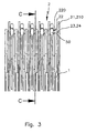
- Fig. 3 shows the needle bed 1, equipped with the cassettes 2 according to a first embodiment.
- the stored in the needle bed 1 cassettes 2 have side plates 21, 22, which contain the necessary for the stitch formation active elements. Between the side plates 21, 22 active elements are arranged, which favor the stitch formation.
- a Cassette 2 is formed on the side plate 21 of the mesh images 210 and on the side plate 22, the tee edge 220. Between the side plates 21, 22 in the slide 24 pivotally mounted hold-down plate 23 is arranged.
- the needle 50 receives in the stitching area an additional lateral guidance through the cassettes 2, which are located to the left and right of the needle.
- Fig. 4 shows the stitching area of the needle bed 1 with a cassette 2 according to a first embodiment in a view according to the section CC of Fig. 3 ,
- the side plate 22 protrudes with its portion 223 and the spring leg 221 in the guide groove 11 of the needle bed 1.
- the spring leg 221 of the side plate 22 includes with its notch 222 partially the round bar 6, which is mounted in the groove 14 of the needle bed 1 and thereby fixes the cassette 2 with respect to the needle bed longitudinal side.
- the laterally projecting from the side plate 22 bolt 220 forms the tee edge for his correspondence needle and extends to the outside of the side plate 21 of the subsequent cassette.
- the spring leg 221 is locked on the round rod 6. Since the spring leg 221 is deflectable against a restoring force, it can be deducted from the round rod 6. For replacement of the cassette 2, the round rod 6 therefore does not have to be removed.
- the side plate 21 of the cassette 2 rests with its surface 211 on the surface 15 of the needle bed 1 and thus determines the height position of the cassette 2 to the needle 50.
- the nose 212 of the side plate 21 abuts the surface 16 of the needle bed 1 and forms The slope at the front of the side plate 21 is the stitch pattern 210.
- the bolts 25, 26 also form the connection of the side plate 21 with the side plate 22.
- the hold-down plate 23 is pivotally mounted in the slider 24 and therefore can perform pivotal movements when it is acted upon by non-illustrated cam tracks on the section 232. With the nose 230 of the hold-down plate 23, the mesh, which is in the stitch formation in the needle hook, are retained when the needle 50 executes its ejection movement.
- each cassette 2 can be inserted independently of other cassettes in a movement in their guide groove 11 in the needle bed 1, in which the spring leg 221 snaps with its notch 222 on the rod 6 and automatically fixes the cassette.
- the locking configuration shown is one of many Verrastungshow with which the cassette 2 in the needle bed 1 can be fixed. It is also conceivable that all the cassettes 2 of the needle bed 1, which are inserted into their guide groove 11, are fixed with a wedge-shaped strip whose profile is encompassed by a groove in each cassette 2 and a groove extending in the needle bed 1 over the entire length of the needle bed ,
- Fig. 5a shows a section of the stitch-forming region of the needle bed 1 ', in which the cassettes 2' corresponding to a further embodiment, which contain the elements necessary for the stitch formation are stored, in one of Fig. 2a corresponding view.
- Fig. 5b shows the area of the needle bed 1 ', in which the cassettes 2' are stored, in a view according to the section DD of Fig. 5a ,
- the needle bed 1 ' has on its longitudinal side, on which the stitch formation happens, before each Nadelelnut 18' the tee edge 19. Otherwise corresponds to the contour and the groove of the needle bed 1 'of the needle bed 1. Components that correspond to those of the previous figures have same reference number with trailing '.
- Fig. 6 shows the stitching area of the needle bed 1 'with a cassette 2' according to another embodiment in one of Fig. 4 corresponding view.
- the cassette 2 'does not have the abutment edge forming bolt 220 (FIG. Fig. 4 ), because the tee edge 19 is formed for each needle 50 through the needle bed 1 '.
- the cassette 2 in its structure, its functionality and in its storage in the needle bed 1' identical to the cassette. 2
- Fig. 7a - 7d show the flat components from which the cassette 2 is formed according to a first embodiment.
- the side plate 21 lies with its surface 211 on the needle bed 1 and therefore determines the height position of the cassette 2 to the needle 50.
- the nose 212 engages around the surface 16 of the needle bed 1 and forms the height fixing of the cassette 2.
- the at the front of the side plate 21st formed bevel 210 is the stitch pattern, which is a necessary for the stitch formation active element.
- the bores 214 and 215 receive the bearing bolts for the slider 24.
- the distance nubs 216 form the gap which is needed between the side plates 21, 22 so that the slider 24 can perform its sliding movement and the hold-down plate 23 their pivotal movement.
- the hold-down plate 23 is mounted with its circular portion 231 in the slider 24 and can perform pivotal movements by applying the portion 232.
- the hold-down plate 23 with its nose 230 is the active element, which favors the formation of stitches.
- Fig. 7d engages the side plate 22 with its portion 223 and its spring leg 221 in the guide groove 11 of the needle bed 1.
- the notch 222 of the spring leg 221 is located on the round bar 6 of the needle bed 1 at.
- the side plate 22 thereby determines the position of the cassette 2 to its correspondence needle and stitch-forming longitudinal side of the needle bed 1.
- the bores 224 and 225 take the bearing pin for the slider 24.
- Of the Bolt 220 is permanently connected to the side plate 22 and forms the knock-off edge for the correspondence needle, ie the needle assigned to the cassette 2.
- the knock-off edge is the necessary for the stitch formation active element.
- the active element mounted between the side plates 21, 22 of the cassette 2, which promotes stitch formation, in the illustrated embodiments of the invention is the hold-down plate 23, which is pivotally mounted in the horizontally displaceable slide 24.
- This configuration of a hold-down plate 23 is only an example of active elements mounted in the cassette 2, which favor the formation of stitches.
- all conceivable hold-down boards, in particular those whose movements are composed of different directions of movement, are stored.
- Hold down plates in which a direction of movement is initiated by the force of a spring, can be stored in the cassette 2 so that the spring can be supported in the cassette 2.
- the stitch formation favoring active elements are stored, for.
- Fig. 8a - 8d show a perspective view of the assembly of the items for a cassette 2, according to a first embodiment of the invention.
- the bolts 25, 26 are inserted ( Fig. 8a ).
- the slide 24 is flat against the side plate 21 and its slots 240, 241 comprise the bolts 25, 26 (FIG. Fig. 8b ).
- the hold-down plate 23 is inserted with its arcuate portion 231 in the circular segments 242 of the slider 24 ( Fig. 8c ).
- the side plate 22 comes to rest on the spacer knobs of the side plate 21 and includes with their bores 224, 225, the bolts 25, 26 (FIG. Fig. 8d ). About the bolts 25, 26, the two side plates 21, 22 are interconnected.
Description
Die Erfindung betrifft eine Kassette, die am Nadelbett einer Strickmaschine befestigbar ist, sowie eine Strickmaschine mit einer solchen Kassette.The invention relates to a cassette which can be fastened to the needle bed of a knitting machine, and to a knitting machine with such a cassette.
Seit es Flachstrickmaschinen gibt, besteht die Gefahr, dass die Maschenbilder, welche aus der maschennahen Längsseite des Nadelbetts herausragen, bei Fadenführer- oder Nadelkollisionen beschädigt werden. Dies hat zunächst dazu geführt, dass die Maschenbilder nicht mehr frästechnisch an der maschennahen Längsseite des Nadelbetts gebildet werden, sondern als eigenständiges Bauteil in die maschennahe Längsseite des Nadelbetts eingefügt werden.Since there are flat knitting machines, there is a risk that the mesh images, which protrude from the stitch-side longitudinal side of the needle bed, are damaged in yarn guide or needle collisions. This has initially led to the mesh images are no longer formed frästechnisch on the stitch-side longitudinal side of the needle bed, but are inserted as a separate component in the stitch-near longitudinal side of the needle bed.
Bei Nadelbetten entsprechend dem Stand der Technik können defekte Teile des Maschenbildungsbereichs ausgetauscht werden. Der Vorgang des Austauschs ist aber nicht einfach und verlangt einen erheblichen Zeitaufwand.In the case of prior art needle beds, defective parts of the stitch forming area may be exchanged. The process of exchange is not easy and requires a considerable amount of time.
Die
Die
Im Nadelbett 1" sind die Nadeln 50 in der Nut 11" geführt. Die Maschenbilder 70 erhalten ihre Höhenfiierung in der Nut 13" des Nadelbetts 1". Die Niederhalteplatinen 80 befinden sich in ähnlicher Position an der maschennahen Längsseite des Nadelbetts 1" wie die Maschenbilder 70 und sind daher auch gefährdet, beschädigt zu werden. Die Maschenbilder 70 und die Niederhalteplatinen 80 werden durch denselben Rundstab 60 in ihrer Position im Nadelbett 1" fixiert. Für die Maschenbilder 70 bildet der Rundstab 60 die Fixierung ihrer Position zur maschennahen Längsseite des Nadelbetts 1" und für die Niederhalteplatinen 80 bildet er zusätzlich die Achse, um welche die Niederhalteplatinen 80 ihre Schwenkbewegungen ausführen. Wenn nun beschädigte Maschenbilder 70 und/oder Niederhalteplatinen 80 ausgetauscht werden müssen und sich diese unvorteilhafterweise in der Mitte des Nadelbetts 1" befinden, muss der Rundstab 60 mindestens um seine halbe Länge seitlich aus dem Nadelbett 1" herausgezogen werden. Ebenfalls mindestens um seine halbe Länge muss der die Abschlagkante bildende Runddraht 90 seitlich aus dem Nadelbett 1" herausgezogen werden, da er von den Maschenbildern 70 kreislochförmig und von den Niederhalteplatinen 80 langlochförmig umfasst wird. Häufig hat der Runddraht 90 durch verformte Maschenbilder 70 eine Knickstelle bekommen und kann deshalb nicht durch die Bohrungen der Maschenbilder 70 und Niederhalteplatinen 80 in einer Richtung herausgezogen werden. In diesem Fall muss der Runddraht 90 vor und nach der Knickstelle durchtrennt werden, um dann an beiden Enden des Nadelbetts 1" aus diesem entfernt werden zu können. Sobald der Rundstab 60 und der Runddraht 90 eine Stecke aus dem Nadelbett 1" herausgezogen werden, verlieren die Maschenbilder 70 und die Niederhalteplatinen 80, welche keinen Kontakt mehr zu dem Rundstab 60 und dem Runddraht 90 haben, ihre exakte Fixierung und befinden sich in indifferenter Position im Nadelbett 1". Diese indifferente Position der Maschenbilder 70 und der Niederhalteplatinen 80 erschwert das Einschieben des Rundstabs 60 in das Nadelbett 1", wenn die beschädigten Maschenbilder 70 und/oder Niederhalteplatinen 80 durch funktionsfähige ausgetauscht sind, denn bei jedem Maschenbilder 70 und jeder Niederhalteplatine 80 muss der Rundstab 60 durch die Fixierbohrung hindurch gleiten. Das Einschieben des Runddrahts 90 ist bedingt durch seinen kleinen Durchmesser und die entsprechend kleinen Löcher in den Maschenbildern 70 auch schwierig.In the
Aufgabe der vorliegenden Erfindung ist es daher, diesbezüglich Abhilfe zu schaffen und insbesondere einen einfacheren Austausch beschädigter Elemente des Maschenbildungsbereichs zu ermöglichen.Object of the present invention is therefore to remedy this situation and in particular to allow easier replacement of damaged elements of the stitch formation area.
Gelöst wird diese Aufgabe erfindungsgemäß durch eine Kassette, die am Nadelbett einer Strickmaschine lösbar befestigbar ist und zumindest ein für eine Maschenbildung benötigtes Wirkelement aufweist. Dabei ist vorzugsweise jedem Strickwerkzeug, insbesondere jeder Nadel, eine Kassette zugeordnet. Die Kassetten können unabhängig von einem Rundstab oder Runddraht an dem Nadelbett befestigt werden. Für die Maschenbildung benötigte Wirkelemente können beispielsweise ein Maschenbilder und/oder eine Abschlagkante sein.This object is achieved according to the invention by a cassette which is detachably fastened to the needle bed of a knitting machine and has at least one active element required for stitch formation. In this case, preferably each knitting tool, in particular each needle, a cassette assigned. The cassettes can be attached to the needle bed independently of a round bar or round wire. For example, knitting elements needed for the stitch formation can be a stitch pattern and / or a knock-off edge.
Besondere Vorteile ergeben sich, da die Kassette lösbar an dem Nadelbett befestigbar ist. Dadurch entsteht die Möglichkeit, einzelne Kassetten, die beschädigte Wirkelemente aufweisen, auszutauschen. Es muss nicht erst ein Rundstab bzw. Runddraht, der mit allen Wirkelementen in Verbindung steht, entfernt werden, ehe ein beschädigtes Wirkelement ausgetauscht werden kann. Die Reparatur und Instandsetzung einer Strickmaschine kann dadurch erheblich schneller erfolgen.Particular advantages arise because the cassette is releasably attachable to the needle bed. This creates the opportunity to exchange individual cartridges that have damaged active elements. It is not necessary to first remove a round rod or round wire which is in contact with all the active elements before a damaged active element can be exchanged. The repair and repair of a knitting machine can thus be done much faster.
Besonders bevorzugt ist es, wenn die Kassette an dem Nadelbett verrastbar ist. Durch eine Rastverbindung kann eine besonders einfache und zuverlässige Befestigung an dem Nadelbett hergestellt werden. Außerdem ist eine Rastverbindung in der Regel einfach lösbar, sodass ein Austausch einer Kassette schnell erfolgen kann.It is particularly preferred if the cassette can be locked on the needle bed. By a locking connection, a particularly simple and reliable attachment to the needle bed can be made. In addition, a locking connection is usually easily solvable, so that a replacement of a cassette can be done quickly.
Weitere Vorteile ergeben sich, wenn die Kassette werkzeuglos an dem Nadelbett befestigbar und/oder von dem Nadelbett lösbar ist. Auch dadurch kann der Austausch einer Kassette noch beschleunigt werden. Das Anbringen oder Entfernen der Kassette am Nadelbett kann daher ohne technische Hilfsmittel erfolgen. Dadurch ist es möglich, das Nadelbett nur mit Nuten und Ausfräsungen zu versehen, welche zur Führung und Lagerung der Strickwerkzeuge und der Kassetten benötigt werden. Zusätzliche Befestigungsmittel müssen an den Nadelbetten nicht vorgesehen werden. Insbesondere müssen keine Gewinde geschnitten werden, um die Kassetten am Nadelbett befestigen zu können.Further advantages result if the cassette can be attached to the needle bed without tools and / or can be detached from the needle bed. This also makes it possible to speed up the replacement of a cassette. The attachment or removal of the cassette on the needle bed can therefore be done without technical aids. This makes it possible to provide the needle bed only with grooves and cutouts, which are needed for guiding and storing the knitting tools and the cassettes. Additional fasteners need not be provided on the needle beds. In particular, no threads need to be cut to secure the cassettes to the needle bed.
In einer Ausgestaltung der Erfindung kann vorgesehen sein, dass die Kassette einen Maschenbilder und/oder eine Abschlagkante aufweist. Dadurch müssen diese Elemente nicht separat am Nadelbett ausgebildet werden.In one embodiment of the invention it can be provided that the cassette has a stitch pattern and / or a knock-off edge. As a result, these elements do not have to be formed separately on the needle bed.
Weitere Vorteile ergeben sich, wenn die Kassette zumindest ein die Maschenbildung erleichterndes Wirkelement aufweist. Insbesondere kann die Kassette eine Niederhalteplatine und/oder einen Maschenabstreifer und/oder einen Fadenzuweiser aufweisen. Es ist auch möglich, Kombinationen der genannten Elemente in den Kassetten zu lagern.Further advantages result if the cassette has at least one knitting element which facilitates the stitch formation. In particular, the cassette may have a hold-down plate and / or a mesh wiper and / or a yarn feeder. It is also possible to store combinations of said elements in the cassettes.
Gemäß einer Ausführungsform der Erfindung kann vorgesehen sein, dass die Kassette zumindest eine Seitenplatte aufweist, die ein für die Maschenbildung benötigtes Wirkelement umfasst oder zumindest teilweise als solches ausgebildet ist. Insbesondere können zwei Seitenplatten vorgesehen sein, die die für die Maschenbildung benötigten Wirkelemente enthalten.According to one embodiment of the invention, provision can be made for the cassette to have at least one side plate which comprises or is at least partially designed as an active element needed for stitch formation. In particular, two side plates may be provided which contain the active elements needed for stitch formation.
Weiterhin kann vorgesehen sein, dass an einer ersten Seitenplatte ein Maschenbilder und an einer zweiten Seitenplatte eine Abschlagkante ausgebildet ist. Zwischen den Seitenplatten können Wirkelemente angeordnet sein, welche die Maschenbildung begünstigen. Eine besonders einfache Ausgestaltung einer Abschlagkante ergibt sich, wenn als Abschlagkante Bolzen an den Seitenplatten angeordnet sind.Furthermore, it can be provided that a stitch pattern is formed on a first side panel and a knock-off edge on a second side panel. Between the side plates knitting elements can be arranged, which favor the stitch formation. A particularly simple embodiment of a knock-off edge is obtained when bolts are arranged on the side plates as a knock-off edge.
Zwischen zwei Seitenplatten kann eine Niederhalteplatine angeordnet sein, die wiederum an einem Schieber angeordnet ist, der relativ zu den Seitenplatten beweglich ist.Between two side plates, a hold-down board may be arranged, which in turn is disposed on a slider which is movable relative to the side plates.
Gemäß einer bevorzugten Ausgestaltung der Erfindung kann vorgesehen sein, dass eine Seitenplatte einen Abschnitt aufweist, mit dem sie in einer Führung des Nadelbetts angeordnet werden kann. Durch diese Maßnahme kann die Kassette in ihrer Lage zu ihrer Korrespondenznadel im Nadelbett fixiert werden.According to a preferred embodiment of the invention can be provided that a side plate has a portion with which it can be arranged in a guide of the needle bed. By this measure, the cassette can be fixed in position to its correspondence needle in the needle bed.
Zur Fixierung am Nadelbett kann die Kassette einen Federschenkel mit einer Einkerbung aufweisen. Dabei kann der Federschenkel mit seiner Einkerbung einen Rundstab umfassen, der in einer Nut des Nadelbetts gelagert ist. Dadurch kann die Kassette in Bezug zur Nadelbettlängsseite fixiert werden. Weiterhin kann vorgesehen sein, dass die Seitenplatten der Kassette mittels Bolzen verbunden sind und ein in der Kassette beweglicher Schieber durch die Bolzen geführt ist.For fixing to the needle bed, the cassette may have a spring leg with a notch. In this case, the spring leg with its notch may comprise a round rod which is mounted in a groove of the needle bed. As a result, the cassette can be fixed in relation to the needle bed longitudinal side. Furthermore, it can be provided that the side plates of the cassette are connected by means of bolts and a slide movable in the cassette is guided by the bolts.
In den Rahmen der Erfindung fällt außerdem eine Strickmaschine mit mindestens einem Nadelbett und relativ zum Nadelbett beweglichen Strickwerkzeugen, insbesondere Nadeln, wobei jedem Strickwerkzeug eine erfindungsgemäße Kassette zugeordnet ist. Bei einer solchen Strickmaschine können beschädigte Wirkelemente besonders einfach ausgetauscht werden, indem die Kassetten, in denen die Wirkelemente angeordnet sind, ausgetauscht werden. Der Austausch einer Kassette kann ohne irgendeine Auswirkung auf eine andere Kassette erfolgen.In the scope of the invention also a knitting machine with at least one needle bed and relative to the needle bed movable knitting tools, in particular needles, wherein each knitting tool is associated with a cassette according to the invention. In such a knitting machine, damaged active elements can be exchanged particularly easily by exchanging the cassettes in which the active elements are arranged. The replacement of one cartridge can be done without any impact on another cartridge.
Um die Kassetten exakt bezüglich den zugeordneten Nadeln am Nadelbett anordnen zu können, ist es vorteilhaft, wenn das Nadelbett Führungen für die Kassetten aufweist. Dadurch wird die Position der Kassetten definiert.In order to be able to arrange the cassettes exactly with respect to the associated needles on the needle bed, it is advantageous if the needle bed has guides for the cassettes. This defines the position of the cartridges.
Damit die Kassetten und Nadeln sich nicht gegenseitig stören, ist es vorteilhaft, wenn die Führungen für die Kassetten und Führungen für die Nadeln zumindest in einem Maschenbildungsbereich parallel verlaufen.In order that the cassettes and needles do not interfere with each other, it is advantageous if the guides for the cassettes and guides for the needles are parallel at least in a stitch formation area.
Am Nadelbett können Freisparungen für Wirknasen von in den Kassetten angeordneten Niederhalteplatinen vorgesehen sein. Die Freisparungen können senkrecht zu einer sich in Längsrichtung des Nadelbetts erstreckenden Ebene des Nadelbetts angeordnet sein. Dabei kann das vordere Ende der Freisparung verbreitert sein. In dieser Verbreiterung kann die Kassette im maschenbildungsnahesten Bereich des Nadelbetts seitlich geführt werden.At the needle bed recesses may be provided for impact noses arranged in the cassette hold-down. The recesses may be arranged perpendicular to a plane of the needle bed extending in the longitudinal direction of the needle bed. In this case, the front end of the cutout can be widened. In this widening, the cassette can be guided laterally in the area of the needle bed that is closest to the stitching.
An dem Nadelbett kann ein Höhenfixierungsanschlag für die Kassetten vorgesehen sein. Insbesondere kann dazu eine abgesetzte Fläche vorgesehen sein, welche parallel zu einer Ebene in Längsrichtung des Nadelbetts verläuft. Weitere Vorteile ergeben sich, wenn zumindest eine Nadel durch zwei Kassetten seitlich geführt ist. Somit kann die Nadel zusätzlich seitlich geführt werden.At the needle bed, a height fixing stop for the cassettes can be provided. In particular, a stepped surface can be provided for this, which extends parallel to a plane in the longitudinal direction of the needle bed. Further advantages arise when at least one needle is guided laterally by two cassettes. Thus, the needle can be additionally guided laterally.
Wie schon erwähnt, ist es besonders vorteilhaft, wenn die Kassetten am Nadelbett verrastet sind. Dadurch lassen sie sich auch wieder einfach vom Nadelbett entfernen, sodass sie gegebenenfalls ausgetauscht werden können.As already mentioned, it is particularly advantageous if the cassettes are locked on the needle bed. As a result, they can also be easily removed from the needle bed so that they can be replaced if necessary.
Eine alternative Befestigungsmöglichkeit der Kassetten besteht darin, dass diese mittels einer keilförmigen Leiste am Nadelbett fixiert sind.An alternative mounting option of the cassettes is that they are fixed by means of a wedge-shaped strip on the needle bed.
An dem Nadelbett kann eine Abschlagkante vorgesehen sein. Insbesondere kann sie an dem Nadelbett ausgebildet sein.At the needle bed, a knock-off edge may be provided. In particular, it may be formed on the needle bed.
Weitere Merkmale und Vorteile der Erfindung ergeben sich aus der nachfolgenden detaillierten Beschreibung von Ausführungsbeispielen der Erfindung, anhand der Figuren der Zeichnung, die erfindungswesentliche Einzelheiten zeigen, sowie aus den Ansprüchen. Die einzelnen Merkmale können je einzeln für sich oder zu mehreren in beliebigen Kombinationen bei Varianten der Erfindung verwirklicht sein.Further features and advantages of the invention will become apparent from the following detailed description of embodiments of the invention, with reference to the figures of the drawing, which show details essential to the invention, and from the claims. The individual features may be implemented individually for themselves or for a plurality of combinations in variants of the invention.
In der schematischen Zeichnung ist ein Ausführungsbeispiel der Erfindung dargestellt und in der nachfolgenden Beschreibung näher erläutert.In the schematic drawing an embodiment of the invention is shown and explained in more detail in the following description.
Es zeigen:
- Fig. 1a
- einen Ausschnitt des Maschenbildungsbereichs eines Nadelbetts gemäß dem Stand der Technik in einer Ansicht von oben;
- Fig. 1b
- eine Schnittdarstellung gemäß der Linie A-A der
Fig. 1a ; - Fig. 2a
- eine Ansicht von oben auf einen Ausschnitt eines Maschenbil- dungsbereichs eines Nadelbetts, in dem Kassetten gelagert wer- den können;
- Fig. 2b
- eine Schnittdarstellung gemäß der Linie B-B der
Fig. 2a ; - Fig. 3
- ein Nadelbett, welches Kassetten aufweist;
- Fig. 4
- eine Schnittdarstellung gemäß der Linie C-C der
Fig. 3 ; - Fig. 5a
- einen Ausschnitt eines Maschenbildungsbereichs eines Nadelbetts für eine alternative Ausgestaltung einer Kassette;
- Fig. 5b
- eine Schnittdarstellung gemäß der Linie D-D der
Fig. 5a ; - Fig. 6
- eine der
Fig. 4 entsprechende Ansicht mit einer alternativen Aus- gestaltung einer Kassette; - Fig. 7a - 7d
- die Bestandteile einer ersten Ausführungsform einer Kassette;
- Fig. 8a - 8d
- in perspektivischer Darstellung das Zusammenfügen der Einzel- teile für eine Kassette gemäß einer ersten Ausführungsform.
- Fig. 1a
- a section of the stitching area of a needle bed according to the prior art in a view from above;
- Fig. 1b
- a sectional view along the line AA of
Fig. 1a ; - Fig. 2a
- a view from above of a section of a stitch forming area of a needle bed, in which cassettes can be stored;
- Fig. 2b
- a sectional view along the line BB of
Fig. 2a ; - Fig. 3
- a needle bed having cassettes;
- Fig. 4
- a sectional view along the line CC of
Fig. 3 ; - Fig. 5a
- a section of a stitching area of a needle bed for an alternative embodiment of a cassette;
- Fig. 5b
- a sectional view along the line DD of
Fig. 5a ; - Fig. 6
- one of the
Fig. 4 corresponding view with an alternative design of a cassette; - Fig. 7a - 7d
- the components of a first embodiment of a cassette;
- Fig. 8a - 8d
- in a perspective view the assembly of the individual parts for a cassette according to a first embodiment.
Das Nadelbett 1 enthält die Nuten 18, in welchen die Nadeln 50 gelagert sind, die zwar nur im dargestellten Bereich sichtbar sind, aber über den Maschenbildungsbereich hinaus rechtwinklig zur Nadelbettlängsseite über die gesamte Breite des Nadelbetts verlaufen. Im Maschenbildungsbereich sind die Nuten 11 parallel zu den Nuten 18 eingebracht. In ihnen werden die Kassetten 2 (
Die Seitenplatte 22 ragt mit ihrem Abschnitt 223 und dem Federschenkel 221 in die Führungsnut 11 des Nadelbetts 1. Dadurch wird die Kassette 2 in ihrer Lage zu ihrer Korrespondenznadel fixiert. Der Federschenkel 221 der Seitenplatte 22 umfasst mit seiner Einkerbung 222 teilweise den Rundstab 6, welcher in der Nut 14 des Nadelbetts 1 gelagert ist und fixiert dadurch die Kassette 2 in Bezug zur Nadelbettlängsseite. Der von der Seitenplatte 22 seitlich abstehende Bolzen 220 bildet die Abschlagkante für seine Korrespondenznadel und erstreckt sich bis zur Außenseite der Seitenplatte 21 der nachfolgenden Kassette. Der Federschenkel 221 ist am Rundstab 6 verrastet. Da der Federschenkel 221 gegen eine Rückstellkraft auslenkbar ist, kann er vom Rundstab 6 abgezogen werden. Zum Austausch der Kassette 2 muss der Rundstab 6 daher nicht entfernt werden. Die Seitenplatte 21 der Kassette 2 liegt mit ihrer Fläche 211 auf der Fläche 15 des Nadelbetts 1 auf und bestimmt somit die Höhenposition der Kassette 2 zu der Nadel 50. Die Nase 212 der Seitenplatte 21 kommt an der Fläche 16 des Nadelbetts 1 zur Anlage und bildet dadurch die Höhenfixierung der Kassette 2. Die Schräge an der Vorderseite der Seitenplatte 21 ist der Maschenbilder 210. Auf den Bolzen 25 und 26, die in die Seitenplatten 21, 22 eingreifen, gleitet der Schieber 24, wenn er durch nicht dargestellte Kurvenbahnen am Abschnitt 243 beaufschlagt wird. Die Bolzen 25, 26 bilden zudem die Verbindung der Seitenplatte 21 mit der Seitenplatte 22. Die Niederhalteplatine 23 ist im Schieber 24 schwenkbar gelagert und kann daher Schwenkbewegungen ausführen, wenn sie durch nicht dargestellte Kurvenbahnen an dem Abschnitt 232 beaufschlagt wird. Mit der Nase 230 der Niederhalteplatine 23 kann die Masche, welche sich beim Maschenbildungsvorgang im Nadelhaken befindet, zurückgehalten werden, wenn die Nadel 50 ihre Austriebsbewegung ausführt.The
Bei der gezeigten, bevorzugten Ausgestaltung kann jede Kassette 2 unabhängig von anderen Kassetten in einem Bewegungsablauf in ihre Führungsnut 11 im Nadelbett 1 eingeschoben werden, in welcher der Federschenkel 221 mit seiner Einkerbung 222 an dem Rundstab 6 einrastet und sich die Kassette automatisch fixiert. Die gezeigte Verrastungskonfiguration ist eine von vielen Verrastungsmöglichkeiten, mit welchen die Kassette 2 im Nadelbett 1 fixiert werden kann. Es ist auch vorstellbar, dass alle Kassetten 2 des Nadelbetts 1, die in ihre Führungsnut 11 eingeschoben sind, mit einer keilförmigen Leiste fixiert werden, deren Profil von einer Nut in jeder Kassette 2 und einer über die gesamte Nadelbettlänge verlaufenden Nut im Nadelbett 1 umfasst wird.In the preferred embodiment shown, each
Das Nadelbett 1' hat an seiner Längsseite, an welcher die Maschenbildung geschieht, vor jeder Nadelnut 18' die Abschlagkante 19. Ansonsten entspricht die Kontur und die Nutung des Nadelbetts 1' der von Nadelbett 1. Bauteile, die denen der vorherigen Figuren entsprechen, haben dieselbe Bezugsziffer mit nachgestellten'.The needle bed 1 'has on its longitudinal side, on which the stitch formation happens, before each Nadelelnut 18' the
Ansonsten ist die Kassette 2' in ihrem Aufbau, ihrer Funktionalität und in ihrer Lagerung im Nadelbett 1' identisch mit der Kassette 2.Otherwise, the cassette 2 'in its structure, its functionality and in its storage in the needle bed 1' identical to the cassette. 2
Ausweislich
Ausweislich
Ausweislich
Ausweislich
Claims (21)
- Cassette (2, 2') that is mounted detachable at the needle bed (1, 1') of a knitting machine and is provided with at least one operative element that is required for forming a knitting stitch.
- Cassette according to claim 1, characterized by, that the cassette (2, 2') can be snapped in at the needle bed (1, 1').
- Cassette according to one of the preceding claims, characterized by, that the cassette (2, 2') can be fastened at the needle bed (1, 1') and/or detached from the needle bed (1, 1') without any tools.
- Cassette according to one of the preceding claims, characterized by, that the cassette (2, 2') is provided with a stitch generator (210, 210') and/or is provided with a bind-off edge (220).
- Cassette according to one of the preceding claims, characterized by, that the cassette (2, 2') is provided at least with one operative element that makes stitch generation easier.
- Cassette according to claim 5, characterized by, that the cassette is provided with a hold-down plate (23) and/or a stitch stripper and/or a thread allocator.
- Cassette according to one of the preceding claims, characterized by, that the cassette (2, 2') is provided with at least one lateral plate (21, 22) that comprises an operative element that is required for generating stitches or is designed as such at least partially.
- Cassette according to claim 7, characterized by, that at a first lateral plate (21) a stitch generator (210, 210') and at a second lateral plate (22), a bind-off edge (220) is formed.
- Cassette according to one of the preceding claims 7 or 8, characterized by, that a hold-down plate (23) is located between the lateral plates (21, 22).
- Cassette according to one of the preceding claims 7 to 9, characterized by, that a lateral plate (22) is provided with a section (223) by means of which it can be mounted in a guide of the needle bed (1, 1').
- Cassette according to one of the preceding claims 7 to 10, characterized by, that the lateral plates (21, 22) of the cassette are connected by means of bolts (25, 26) and a slider (24) that is displaceable in the cassette (2, 2') is guided by bolts (25, 26).
- Cassette according to one of the preceding claims, characterized by, that the cassette (2, 2') for fixation at the needle bed (1, 1') is provided with a spring bracket (221) with a notch (222).
- Knitting machine with at least one needle bed and knitting tools that are displaceable relative to the needle bed, whereby each knitting tool (50) is associated with a cassette (2, 2') according to one of the preceding claims.
- Knitting machine according to claim 13, characterized by, that the needle bed (1, 1') is provided with guides for the cassettes (2, 2').
- Knitting machine according to one of claims 13 or 14, characterized by, that the guides for the cassettes (2, 2') and guides for the needles extend parallel at least in a stitch generating section.
- Knitting machine according to one of the preceding claims 13 to 15, characterized by, that cut outs (12) for the operative catches of the hold-down plates (23) that are located in the cassettes are provided at the needle bed (1, 1').
- Knitting machine according to one of the preceding claims 13 to 16, characterized by, that at the needle bed (1, 1') a height fixation stop is provided for cassettes (2, 2').
- Knitting machine according to one of the preceding claims 13 to 17, characterized by, that at least one needle (50) is guided laterally by two cassettes (2, 2').
- Knitting machine according to one of the preceding claims 13 to 18, characterized by, that the cassettes (2, 2') are snapped in at the needle bed (1, 1').
- Knitting machine according to one of the preceding claims 13 to 18, characterized by, that the cassettes (2, 2') are fixated at needle bed (1, 1') by means of a wedge-shaped bar.
- Knitting machine according to one of the preceding claims 13 to 20, characterized by, that a bind-off edge (19) is provided at the needle bed (1, 1').
Priority Applications (3)
| Application Number | Priority Date | Filing Date | Title |
|---|---|---|---|
| EP20080000532 EP2078773B1 (en) | 2008-01-12 | 2008-01-12 | Cartridge of a knitting machine |
| DE200850001881 DE502008001881D1 (en) | 2008-01-12 | 2008-01-12 | Cassette of a knitting machine |
| CN 200910002902 CN101481849B (en) | 2008-01-12 | 2009-01-12 | loom box |
Applications Claiming Priority (1)
| Application Number | Priority Date | Filing Date | Title |
|---|---|---|---|
| EP20080000532 EP2078773B1 (en) | 2008-01-12 | 2008-01-12 | Cartridge of a knitting machine |
Publications (2)
| Publication Number | Publication Date |
|---|---|
| EP2078773A1 EP2078773A1 (en) | 2009-07-15 |
| EP2078773B1 true EP2078773B1 (en) | 2010-11-24 |
Family
ID=39092622
Family Applications (1)
| Application Number | Title | Priority Date | Filing Date |
|---|---|---|---|
| EP20080000532 Active EP2078773B1 (en) | 2008-01-12 | 2008-01-12 | Cartridge of a knitting machine |
Country Status (3)
| Country | Link |
|---|---|
| EP (1) | EP2078773B1 (en) |
| CN (1) | CN101481849B (en) |
| DE (1) | DE502008001881D1 (en) |
Families Citing this family (3)
| Publication number | Priority date | Publication date | Assignee | Title |
|---|---|---|---|---|
| DE102015103639B4 (en) | 2015-03-12 | 2020-04-23 | Terrot Gmbh | Needle cylinder and circular knitting machine |
| CN106894152B (en) * | 2017-03-31 | 2018-11-23 | 浙江丰帆数控机械有限公司 | A kind of flat machine |
| CN107366083B (en) * | 2017-08-16 | 2023-05-23 | 江苏工程职业技术学院 | Special threading board of hand flat knitting machine |
Family Cites Families (10)
| Publication number | Priority date | Publication date | Assignee | Title |
|---|---|---|---|---|
| GB1140627A (en) * | 1966-04-20 | 1969-01-22 | Empisal Ltd | Flat needle bed for a knitting machine |
| CH575031A5 (en) * | 1974-03-15 | 1976-04-30 | Dubied & Cie Sa E | |
| KR0123800B1 (en) * | 1989-12-28 | 1997-11-27 | 마사히로 시마 | Sinker mechanism for knitting machine |
| JP2700204B2 (en) * | 1992-12-15 | 1998-01-19 | 株式会社島精機製作所 | Sinker device in flat knitting machine |
| TW522186B (en) * | 1999-11-17 | 2003-03-01 | Shima Seiki Mfg | Sinker device of flat knitting machine |
| CN2429538Y (en) * | 2000-06-02 | 2001-05-09 | 邵国平 | Detachable flexible latch needle block |
| CN2534206Y (en) * | 2002-01-31 | 2003-02-05 | 萧世贤 | Needle ruler protector on hand transverse braiding machine frame needle bed |
| DE50208648D1 (en) * | 2002-03-23 | 2006-12-21 | Stoll & Co H | Flat knitting machine with adjustable sinkers |
| US6978642B2 (en) * | 2002-05-30 | 2005-12-27 | Shima Seiki Manufacturing Limited | Weft knitting machine with movable sinker device |
| DE10227532B4 (en) * | 2002-06-20 | 2006-02-23 | Groz-Beckert Kg | Module for textile machines, in particular mesh-forming machines |
-
2008
- 2008-01-12 EP EP20080000532 patent/EP2078773B1/en active Active
- 2008-01-12 DE DE200850001881 patent/DE502008001881D1/en active Active
-
2009
- 2009-01-12 CN CN 200910002902 patent/CN101481849B/en active Active
Also Published As
| Publication number | Publication date |
|---|---|
| EP2078773A1 (en) | 2009-07-15 |
| DE502008001881D1 (en) | 2011-01-05 |
| CN101481849A (en) | 2009-07-15 |
| CN101481849B (en) | 2013-03-06 |
Similar Documents
| Publication | Publication Date | Title |
|---|---|---|
| DE2828278C2 (en) | Needle arrangement for a tufting machine | |
| DE4223642A1 (en) | TUFTING MACHINE WITH SELF-ALIGNING ADJUSTMENT MODULES | |
| EP3347512B1 (en) | Loom for producing woven goods with incorporated knitting or covering threads | |
| DE4421388C2 (en) | Needle attachment device for knitting machines | |
| DE3321733A1 (en) | CHAIN KNITTING MACHINE WITH JACQUARD HOLE NEEDLES | |
| EP2078773B1 (en) | Cartridge of a knitting machine | |
| EP3354781B1 (en) | Knitting element bar | |
| DE3023952A1 (en) | Warp knitting machine | |
| DE3241153C2 (en) | Enclosing and knock-off sinkers for knitting machines | |
| DD298137A5 (en) | KNITTING MACHINE | |
| DE102009040739A1 (en) | Method and knitting machine for making knitwear with striped patterns | |
| DE3843837C2 (en) | ||
| DE19855711C2 (en) | Device for attaching knitting elements to the bar of a warp knitting machine | |
| EP3615722A1 (en) | Sinker lock for circular knitting machines | |
| EP0898000A2 (en) | Gripper loom with guiding means to guide a gripper strap and/or a gripper | |
| DE4019111C2 (en) | ||
| EP4019682B1 (en) | Knitting machine with at least one yarn guide | |
| DE4416167C1 (en) | Needle bar mounting for warp knitting machine with compound needles | |
| EP2034063B1 (en) | Flat knitting machine | |
| DE2644790B2 (en) | Flat knitting machine with several auxiliary sinkers | |
| DE2061300A1 (en) | Device for the automatic adjustment of the color and / or the ratio in embroidery machines | |
| DE1685144C3 (en) | Shuttle embroidery machine with a device for changing threads or colors or changing repeats | |
| EP1918439B1 (en) | Thread clamping and severing arrangement with thread assigning and removing device | |
| DE568894C (en) | Method and sinker for knitting reverse cladding on circular knitting machines | |
| CH670665A5 (en) |
Legal Events
| Date | Code | Title | Description |
|---|---|---|---|
| PUAI | Public reference made under article 153(3) epc to a published international application that has entered the european phase |
Free format text: ORIGINAL CODE: 0009012 |
|
| AK | Designated contracting states |
Kind code of ref document: A1 Designated state(s): AT BE BG CH CY CZ DE DK EE ES FI FR GB GR HR HU IE IS IT LI LT LU LV MC MT NL NO PL PT RO SE SI SK TR |
|
| AX | Request for extension of the european patent |
Extension state: AL BA MK RS |
|
| 17P | Request for examination filed |
Effective date: 20091013 |
|
| 17Q | First examination report despatched |
Effective date: 20091109 |
|
| AKX | Designation fees paid |
Designated state(s): DE IT TR |
|
| GRAP | Despatch of communication of intention to grant a patent |
Free format text: ORIGINAL CODE: EPIDOSNIGR1 |
|
| GRAS | Grant fee paid |
Free format text: ORIGINAL CODE: EPIDOSNIGR3 |
|
| GRAA | (expected) grant |
Free format text: ORIGINAL CODE: 0009210 |
|
| AK | Designated contracting states |
Kind code of ref document: B1 Designated state(s): DE IT TR |
|
| REF | Corresponds to: |
Ref document number: 502008001881 Country of ref document: DE Date of ref document: 20110105 Kind code of ref document: P |
|
| PLBE | No opposition filed within time limit |
Free format text: ORIGINAL CODE: 0009261 |
|
| STAA | Information on the status of an ep patent application or granted ep patent |
Free format text: STATUS: NO OPPOSITION FILED WITHIN TIME LIMIT |
|
| 26N | No opposition filed |
Effective date: 20110825 |
|
| REG | Reference to a national code |
Ref country code: DE Ref legal event code: R097 Ref document number: 502008001881 Country of ref document: DE Effective date: 20110825 |
|
| PGFP | Annual fee paid to national office [announced via postgrant information from national office to epo] |
Ref country code: TR Payment date: 20180109 Year of fee payment: 11 |
|
| PGFP | Annual fee paid to national office [announced via postgrant information from national office to epo] |
Ref country code: IT Payment date: 20200122 Year of fee payment: 13 |
|
| REG | Reference to a national code |
Ref country code: DE Ref legal event code: R082 Ref document number: 502008001881 Country of ref document: DE Representative=s name: KOHLER SCHMID MOEBUS PATENTANWAELTE PARTNERSCH, DE Ref country code: DE Ref legal event code: R081 Ref document number: 502008001881 Country of ref document: DE Owner name: KARL MAYER STOLL R&D GMBH, DE Free format text: FORMER OWNER: H. STOLL GMBH & CO. KG, 72760 REUTLINGEN, DE |
|
| PG25 | Lapsed in a contracting state [announced via postgrant information from national office to epo] |
Ref country code: IT Free format text: LAPSE BECAUSE OF NON-PAYMENT OF DUE FEES Effective date: 20210112 |
|
| PG25 | Lapsed in a contracting state [announced via postgrant information from national office to epo] |
Ref country code: TR Free format text: LAPSE BECAUSE OF NON-PAYMENT OF DUE FEES Effective date: 20190112 |
|
| PGFP | Annual fee paid to national office [announced via postgrant information from national office to epo] |
Ref country code: DE Payment date: 20230126 Year of fee payment: 16 |
|
| P01 | Opt-out of the competence of the unified patent court (upc) registered |
Effective date: 20230630 |