EP0526293A1 - Verfahren und Vorrichtung zum Ausführen von Messungen und/oder Eingriffen in einem fertigen Bohrloch oder während des Bohrens - Google Patents
Verfahren und Vorrichtung zum Ausführen von Messungen und/oder Eingriffen in einem fertigen Bohrloch oder während des Bohrens Download PDFInfo
- Publication number
- EP0526293A1 EP0526293A1 EP92401992A EP92401992A EP0526293A1 EP 0526293 A1 EP0526293 A1 EP 0526293A1 EP 92401992 A EP92401992 A EP 92401992A EP 92401992 A EP92401992 A EP 92401992A EP 0526293 A1 EP0526293 A1 EP 0526293A1
- Authority
- EP
- European Patent Office
- Prior art keywords
- connector
- cable
- drill string
- section
- assembly
- Prior art date
- Legal status (The legal status is an assumption and is not a legal conclusion. Google has not performed a legal analysis and makes no representation as to the accuracy of the status listed.)
- Granted
Links
- 238000005259 measurement Methods 0.000 title claims abstract description 31
- 238000005553 drilling Methods 0.000 title claims abstract description 28
- 238000000034 method Methods 0.000 title claims abstract description 19
- 239000004020 conductor Substances 0.000 claims description 16
- 238000005086 pumping Methods 0.000 claims description 6
- 230000005484 gravity Effects 0.000 claims description 5
- 238000011084 recovery Methods 0.000 claims description 5
- 238000007789 sealing Methods 0.000 claims description 3
- FGUUSXIOTUKUDN-IBGZPJMESA-N C1(=CC=CC=C1)N1C2=C(NC([C@H](C1)NC=1OC(=NN=1)C1=CC=CC=C1)=O)C=CC=C2 Chemical compound C1(=CC=CC=C1)N1C2=C(NC([C@H](C1)NC=1OC(=NN=1)C1=CC=CC=C1)=O)C=CC=C2 FGUUSXIOTUKUDN-IBGZPJMESA-N 0.000 claims description 2
- 239000003129 oil well Substances 0.000 claims description 2
- 239000000523 sample Substances 0.000 description 15
- 238000004873 anchoring Methods 0.000 description 9
- 238000002347 injection Methods 0.000 description 7
- 239000007924 injection Substances 0.000 description 7
- 230000005540 biological transmission Effects 0.000 description 6
- 238000012856 packing Methods 0.000 description 6
- 238000006073 displacement reaction Methods 0.000 description 4
- 239000012530 fluid Substances 0.000 description 4
- 238000012550 audit Methods 0.000 description 3
- 239000004459 forage Substances 0.000 description 3
- 238000004519 manufacturing process Methods 0.000 description 3
- 238000007792 addition Methods 0.000 description 2
- 239000000243 solution Substances 0.000 description 2
- 238000012360 testing method Methods 0.000 description 2
- 230000000712 assembly Effects 0.000 description 1
- 238000000429 assembly Methods 0.000 description 1
- 230000015572 biosynthetic process Effects 0.000 description 1
- 239000002360 explosive Substances 0.000 description 1
- 239000006260 foam Substances 0.000 description 1
- 238000009434 installation Methods 0.000 description 1
- 230000004807 localization Effects 0.000 description 1
- 108090000623 proteins and genes Proteins 0.000 description 1
- 238000004080 punching Methods 0.000 description 1
- 239000003507 refrigerant Substances 0.000 description 1
- 230000002441 reversible effect Effects 0.000 description 1
- 238000005070 sampling Methods 0.000 description 1
- 238000000926 separation method Methods 0.000 description 1
- 239000003381 stabilizer Substances 0.000 description 1
- 239000000725 suspension Substances 0.000 description 1
- 238000012549 training Methods 0.000 description 1
Images


Classifications
-
- E—FIXED CONSTRUCTIONS
- E21—EARTH OR ROCK DRILLING; MINING
- E21B—EARTH OR ROCK DRILLING; OBTAINING OIL, GAS, WATER, SOLUBLE OR MELTABLE MATERIALS OR A SLURRY OF MINERALS FROM WELLS
- E21B23/00—Apparatus for displacing, setting, locking, releasing or removing tools, packers or the like in boreholes or wells
- E21B23/14—Apparatus for displacing, setting, locking, releasing or removing tools, packers or the like in boreholes or wells for displacing a cable or a cable-operated tool, e.g. for logging or perforating operations in deviated wells
Definitions
- the present invention relates to a method and a device for carrying out measurements and / or interventions in a well drilled or during drilling by means of an electrical connection connecting the surface to an assembly assembled at the end of a train. of stems. Said assembly comprising measurement and / or intervention means electrically connected to a first connector fixed to the lower part of the first rod.
- the electrical connection comprises a section of cable having at its lower end a second connector adapted to cooperate electrically with the first and at its upper part a first intermediate connector secured to a support, a second intermediate connector adapted to cooperate electrically with the first connector intermediate, said second intermediate connector is fixed to a cable connected to the surface.
- Patent FR-2501777 discloses a method and a device for carrying out measurements and / or interventions from a probe fixed to the end of a rod train, but this document only relates to logging devices. and has no intermediate connectors. It is impossible to rotate the entire packing in the well when the probe is connected because of the presence of the coaxial cable to the drill string or annular when using a side window fitting.
- the present invention makes it possible to connect measurement and / or intervention means included in particular in a drilling assembly and to allow the rotation of the entire lining without the need to bring the entire coaxial cable to the surface by virtue of to intermediate connectors and a suitable support.
- Document GB-1557863 discloses a method and a device for transmitting information coming from a probe lowered into a drill string, said probe being suspended from a section of cable, said section being connected to the surface by means of 'a connector and a cable.
- the probe is lowered to the cable in the packing and must therefore have an outside diameter compatible with the inside passage of the tubular packing and the section is suspended on the surface.
- the present invention allows a dimension of measuring devices no longer linked with the internal diameter of the channel of the rod train. Indeed, in small drilling dimensions, it is sometimes impossible to have certain equipment.
- the invention integrates the means of measurement and / or intervention in casings which may have the external dimension of the drill collars conventionally used in the hole in question.
- the electronic elements are connected to the surface by a device comprising at least a double pair of electrical connectors. To make rod maneuvers in order to descend or ascend, it then suffices only to ascend a limited length of cable, which only causes a very short time loss and allows high capacity transmissions thanks to a cable transmission.
- this invention is economically very advantageous for the phase of controlling the trajectory of the borehole in the curvature and in the substantially horizontal part.
- the tools used in the prior art are in particular transmission by pressure waves in the fluid in order to be able to rotate the whole of the lining without being hindered by a cable or not having to wind up the whole cable.
- the length of the section can correspond to the start dimension of the deviation or Kick-off-point, and as the length of drilling in short radius is limited to a few hundred meters, the maneuvers of the cable connected to the surface are simple and fast during the whole deviation phase.
- the frequency of measurements and interventions with the invention is thus comparable to that which can be obtained with transmissions without electric cable and moreover with less cost and less complexity.
- rotation of the entire packing is permitted when the cable is brought to the surface.
- the invention will be advantageously applied because it provides mechanical support to take up the weight of the cable and the tension forces generated on the cable in particular by an energetic circulation of a fluid. refrigerant Indeed, in very deep boreholes, the tension that a continuous cable would bear is higher than the authorized tension.
- the solution is therefore to have intermediate supports of sections of acceptable length.
- step a) and then b) can be carried out until the length of the drill string corresponds substantially to the length of said section and steps c), e) and f) can then be carried out, said support located substantially on the surface.
- step a), b), c) and g it is also possible to successively carry out steps a), b), c) and g), this last step taking place on the surface, then step d) with said section connected to said cable by said intermediate connectors, step e) and step f).
- the support can keep said section substantially taut.
- the second intermediate connector and the cable can be introduced into the drill string through a special fitting provided with a side opening.
- Said assembly may include directional drilling means, in particular a drilling tool, a downhole motor, deflection tools, location sensors. From the surface, we can receive the location parameters of the device and we can optionally control said drilling means by means of the electrical connection.
- directional drilling means in particular a drilling tool, a downhole motor, deflection tools, location sensors. From the surface, we can receive the location parameters of the device and we can optionally control said drilling means by means of the electrical connection.
- Said support may be adapted to be secured to said train of rods when it is substantially on the surface.
- said support may be adapted to be secured to said rod train by remote control from the surface.
- Said support can be adapted to keep said section substantially taut and the second connectors can be anchored to the first.
- At least one of said second connectors may be equipped with ballast such as load bars and / or a system adapted to pumping to allow respectively the connection by gravity or by pumping of the second connector on the first.
- ballast such as load bars and / or a system adapted to pumping to allow respectively the connection by gravity or by pumping of the second connector on the first.
- the outlet of the cable from inside the drill string may include a sealing means around the cable adapted to let said cable slide in the drill string.
- Said cable can pass through a side window fitting and exit outside the drill string.
- Said section can be adapted to be brought to the surface either by said cable connected by the second intermediate connector, or by a fishing tool adapted to be connected to the upper end of said section.
- Said assembly may include a drilling tool, a downhole motor, deflection tools, location sensors and any measurements and controls may pass through the electrical connection.
- the method and the device can be applied to the recording of measurements and / or to specific interventions in an oil well, while having the possibility of making additions of rods and / or turning said assembly and the string of rods between each measurement and / or intervention.
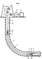
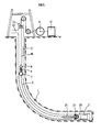
- FIG. 1 represents a well 1 in which there is a drill string 2 at the end of which is assembled an assembly 3 comprising a first connector 4 secured to said assembly 3.
- the assembly comprises means of measurements and interventions electrically connected to the first connector 4.
- a second connector 5 connected to the connector 4 is mechanically fixed to the lower end of a section of cable 6 comprising electrical conductors.
- the upper end of this section has a first intermediate connector 8 secured to a support 7 which secures this first intermediate connector in the inner channel of the drill string.
- the connection of connectors 4 and 5 is locked by a mechanical system which will be described later.
- a second intermediate connector 9 fixed to the end of a cable 10 is connected to the first intermediate connector.
- the cable 10 has electrical conductors, exits through the upper end of the rod train to pass over pulleys before being wound on a winch 11.
- the electrical conductors of this cable are connected to an electrical joint rotating around the axis of the winch drum to be connected to a control cabin 12.
- a circulation head fixed on the upper end of the drill string, is fitted with the conduit 14 which makes it possible to pump the drilling fluid into the internal channel of the drill string, to supply the downhole motor intended to rotate the tool, pump the connectors and clean the ring finger of drilling debris.
- the circulation head has an annular seal 13 adapted to the cable 10. This head is well known in the prior art. In the configuration of FIG. 1, the measurement and intervention means are therefore electrically connected to the surface by the two pairs of connectors, the cable section 6 and the cable 10. It is then possible to operate practically on the length of rods lying above the drill floor while having measurements.
- deflection tools such as an elbow connector and stabilizer with viable geometry which can be controlled by means of the electrical connection going up to the surface.
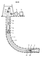
- the operations begin with the descent into the well 1 of the assembly 3 and of its first connector 4 at the end of a length of drill string (FIG. 2).
- a connection 15 is screwed on the top of the rods and the cable section 6 is formed in the following manner: the second is mechanically fixed connector 5 on the end of a length of cable wound on a logging winch, this cable is lowered into the drill string and the connectors 4 and 5 are connected either by gravity or by pumping as described in the patent FR -2501777, the weight of the cable is maintained by collars above the connector 15, the cable is cut substantially above the connector and the first intermediate connector is mechanically fixed on the upper end of the section (FIG. 3).
- the first intermediate connector is secured to a support 7 comprising a jacket 19, said support is then secured to the connector 15.
- FIG. 2A illustrates this connection which is made according to the same techniques as for connectors 4 and 5. Whenever it is necessary to execute an operation made impossible given the presence of the coaxial cable 10, it will suffice first to undock the second intermediate connector 9, to raise the cable 10 to the surface and then to operate. It is thus possible in particular to add rods in a conventional manner to deepen the drilling, to rotate the entire packing from a surface rotation means such as a rotation table or a motorized injection head.
- a surface rotation means such as a rotation table or a motorized injection head.
- the movements can be made both on the descent and on the ascent of the drill string.
- FIG. 3 illustrates an embodiment of a connection and support system 7 of the first intermediate connector 8.
- the cable section 6 is mechanically fixed to the connector 8 by a nut 32.
- the conductors of the cable 6 are connected to the connector 8 by the conductors 31.
- a connector 15 includes lower 16 and upper 17 fixing means to said drill string.
- Suspension arms 18 block the axial downward movement of a jacket 19 by cooperation with a shoulder 20 of the connector 15.
- the arms 18 are adapted to allow free circulation of the fluid in the annular thus created from the outside of the jacket 19 and the interior of said connector 15.
- the arms are secured to the connector 15 by means 30.
- the first intermediate connector 8 is integral with the liner 19. A traction applied to the liner and greater than the shear strength of the screw 21, releases the liner upwards allowing the raising of the jacket, of the first intermediate connector and of the section 6.
- This example is not limiting, it is also possible to equip the jacket 19 with remote-controlled locking fingers from the surface as locking means 21.
- the second intermediate connector 9 connected to the first is locked by means of fingers 22 secured to the jacket, said fingers cooperating with a retaining piece 23 secured to the second intermediate connector. This retaining part 23 can release the second connector when it is broken or be erasable by remote control from the surface of a motorization located above the intermediate connector 9.
- the upper end of the jacket 19 includes a device 24 adapted to cooperate with a recovery tool or overshot (not shown here) lowered inside the rod train to recover the jacket, its first intermediate connector and the entire cable section 6. It is also possible to hang an overshot on the shirt 19 by means of the fingers 22.
- the support 7 cooperates directly with the means for connecting the rods to each other, such as the male and female fittings, without adding an intermediate fitting 15. It suffices that the arms 18 are adapted to be secured to the rods when the male and female threads are screwed together.
- FIGS. 4A and 4B the connection between the intermediate connectors is made on the surface and we descend together into the interior of the drill string the connector 5, the section 6, the support 7 and its connector 8 connected with the connector 9, using the cable 10 and the winch 11.
- the connection of the connectors 4 and 5 is made as described above. It controls the securing of the support 7 with the drill string.
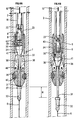
- the production of the support 7 is illustrated by FIGS. 4A and 4B.
- the support 7 is shown in the state in which it is lowered into the pipe 2. It comprises a first connector 8 secured to a jacket 19.
- the jacket 19 is identical to that described in FIG. jacket 19 is secured to a shaft 33 at the end of which the cable section 6 is fixed by means of a nut 32.
- Conductors 31 electrically connect the conductors of the cable section 6 to the intermediate connector 8.
- Around the 'shaft 33 is disposed a body 34 comprising friction pads 35 and anchoring corners 36. This body is in lower support on a shoulder 37 secured to the shaft 33.
- the body 34 is locked in the support position on the shoulder 37 by the cooperation of a finger 39 of a locking system 38 integral with the shaft and a hole 43 in the body 34.
- Each anchoring corner 36 can pivot around an axis 40 perpendicular to the longitudinal axis of the support.
- Springs (not shown) keep the corners closed around the shaft.
- An expansion means 41 of the anchoring corners is integral with the shaft.
- the friction pads 35 are pushed radially by springs 42. These springs 42 provide the necessary contact force between the pipe and the pads to have sufficient longitudinal friction, in addition, they allow the pads to retract as the sections of reduced diameter at the tubular connections.
- the support 7 of the section 6 is connected to the surface by the cable 10 fitted at its lower end with the second intermediate connector 9.
- the locking of this connector 9 is effected by the cooperation of the fingers 22 and of a retaining piece 23 secured to the second connector 9.
- the locking system 38 is electrically controlled from the surface by means of the cable 10 connected to the shaft by the two connectors. It is advantageous that this lock is reversible, that is to say that one can unlock or lock by remote control in particular from the cable 10. Such a lock is known and can be achieved in particular using 'A motor acting on the fingers 39. But in this invention, we can in some cases be satisfied with an unlocking system by breaking the fingers 39, in particular by explosive. In another embodiment, the corners can be secured to the shaft, while the expansion means is secured to the body.
- FIG. 4B shows said support in its state anchored in the pipe 2.
- the lock system 38 has been ordered to be unlocked then by means of the cable 10 the shaft is allowed to slide by a distance H.
- the relative sliding between the shaft and the body is obtained by means of the friction pads which keep the body 34 relatively stationary relative to the pipe and by the action of a downward displacement force of the shaft.
- This force can in particular be provided by the weight of the shaft, the weight of ballast secured to the second connector 9, the weight of the section 6 and / or the tension applied to the section 6 when its end is anchored in the assembly 3.
- the support 7 according to the embodiment of FIG. 4A can be anchored without the preponderant action of the gravity. Just stretch the section to lengthen it by a length greater than H, then unlocking the body of the shaft before releasing the tension to bring the support 7 into the state shown in FIG. 4B.
- the relative displacement of the length H between the shaft and the body causes the expansion means 41 and the anchoring corners to cooperate.
- the conical shape of the expansion means pivots the corners around the axes 40 until these are applied to the wall of the pipe.
- the displacement force as described above maintains the anchoring of the support 7 in the pipeline.
- the external shape and the angle of pivoting of the corners allow the anchoring of the support on sections of the pipe of different diameters.
- the tubulars used, drill rods, casing, tubing, etc. often have variations in internal diameter, particularly at the fittings.
- the present support can be anchored at any level in a pipe having variations in internal diameter.
- the separation or disengagement of the support is done by lowering again the cable 10 and its connector 9 equipped with a part 23 of resistance to rupture greater than the anchoring force. This resistance must also be greater than the force necessary to disengage the section 6 of the assembly 3, in the case where the latter is not remote-controlled. If the retaining part can be erased by remote control, this operation of the cable 10 will be avoided.
- the supports according to the embodiments of FIG. 3 and 4A include electronic means which can be raised with said supports in particular to amplify or help the transmission of information between the probe 25 or the assembly 3 and the surface.
- These electronic means can be located at the upper end of said section 6 or at the lower end of cable 10.
- the support 7 is possibly adapted to be able to keep section 6 substantially taut, the connection of connectors 4 and 5 being locked in particular according to the same principle described in FIG. 3 for connectors 8 and 9 .
- This last arrangement makes it possible to rotate the entire rod train and to make additions, without having to wind up a length of electric cable.
- this solution can be mixed with the use of cable 10 in particular by using above wired rods an adapter fitting comprising an intermediate connector similar to the first intermediate connector 8.
- the connection is made on this connector according to the present invention.
- the known wired rods leave the interior passage free, it will therefore be possible to reassemble the said section through these rods using a recovery tool passing through the wired rods and a suitable support 7.
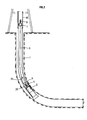
- a variant of the present application relates to the configuration of FIG. 5, where a measurement and / or intervention probe 25 is fixed to the lower part of the section 6.
- the end of this probe cooperates with a connector 26 of the assembly 3.
- the assembly 3 may correspond to that of the previous embodiment, but preferably it does not include measurement and / or intervention means.
- the connector 26 comprises a mechanical anchoring 27 of the probe 25, possibly a system of the Mule-shoe type of angular orientation of said probe.
- the connector 26 also comprises a first connector 4 electrically connected to means for measuring and / or intervention of said assembly, in this case the probe 25 will comprise at its end a second connector 5.
- the probe 25 is adapted to pass through the channel of the drill string, possibly of the wired rods and of the connector 15 if it exists.
- the probe 25 can include a sliding system and load bar facilitating the length adjustment of the cable section 6.
- the cable 10 can pass through a fitting with a side window and rise to the surface by the annular well-drill string. This use is particularly interesting in the case where the operations do not require or more possible rotation of the whole of the drill string.
Landscapes
- Life Sciences & Earth Sciences (AREA)
- Engineering & Computer Science (AREA)
- Geology (AREA)
- Mining & Mineral Resources (AREA)
- Physics & Mathematics (AREA)
- Environmental & Geological Engineering (AREA)
- Fluid Mechanics (AREA)
- General Life Sciences & Earth Sciences (AREA)
- Geochemistry & Mineralogy (AREA)
- Earth Drilling (AREA)
Applications Claiming Priority (2)
| Application Number | Priority Date | Filing Date | Title |
|---|---|---|---|
| FR9109915 | 1991-08-02 | ||
| FR9109915A FR2679957B1 (fr) | 1991-08-02 | 1991-08-02 | Methode et dispositif pour effectuer des mesures et/ou interventions dans un puits fore ou en cours de forage. |
Publications (2)
| Publication Number | Publication Date |
|---|---|
| EP0526293A1 true EP0526293A1 (de) | 1993-02-03 |
| EP0526293B1 EP0526293B1 (de) | 1996-03-06 |
Family
ID=9415914
Family Applications (1)
| Application Number | Title | Priority Date | Filing Date |
|---|---|---|---|
| EP92401992A Expired - Lifetime EP0526293B1 (de) | 1991-08-02 | 1992-07-09 | Verfahren und Vorrichtung zum Ausführen von Messungen und/oder Eingriffen in einem fertigen Bohrloch oder während des Bohrens |
Country Status (5)
| Country | Link |
|---|---|
| US (1) | US5305830A (de) |
| EP (1) | EP0526293B1 (de) |
| CA (1) | CA2075099A1 (de) |
| FR (1) | FR2679957B1 (de) |
| NO (1) | NO923036L (de) |
Cited By (2)
| Publication number | Priority date | Publication date | Assignee | Title |
|---|---|---|---|---|
| EP0674094A1 (de) * | 1994-03-22 | 1995-09-27 | Halliburton Company | Einfahrwerkzeuge im Bohrloch mit gewickeltem Rohrstang |
| FR2745847A1 (fr) * | 1996-03-08 | 1997-09-12 | Inst Francais Du Petrole | Systeme de transmission de mesure comportant un convertisseur optoelectrique |
Families Citing this family (78)
| Publication number | Priority date | Publication date | Assignee | Title |
|---|---|---|---|---|
| EP0747570A1 (de) * | 1992-12-07 | 1996-12-11 | Akishima Laboratories (Mitsui Zosen) Inc. | Druckpuls-Ventil für System für Messungen während des Bohrens |
| US5484029A (en) * | 1994-08-05 | 1996-01-16 | Schlumberger Technology Corporation | Steerable drilling tool and system |
| US5617926A (en) * | 1994-08-05 | 1997-04-08 | Schlumberger Technology Corporation | Steerable drilling tool and system |
| US7036610B1 (en) | 1994-10-14 | 2006-05-02 | Weatherford / Lamb, Inc. | Apparatus and method for completing oil and gas wells |
| US7147068B2 (en) | 1994-10-14 | 2006-12-12 | Weatherford / Lamb, Inc. | Methods and apparatus for cementing drill strings in place for one pass drilling and completion of oil and gas wells |
| US6857486B2 (en) | 2001-08-19 | 2005-02-22 | Smart Drilling And Completion, Inc. | High power umbilicals for subterranean electric drilling machines and remotely operated vehicles |
| US6868906B1 (en) | 1994-10-14 | 2005-03-22 | Weatherford/Lamb, Inc. | Closed-loop conveyance systems for well servicing |
| US7100710B2 (en) | 1994-10-14 | 2006-09-05 | Weatherford/Lamb, Inc. | Methods and apparatus for cementing drill strings in place for one pass drilling and completion of oil and gas wells |
| US7228901B2 (en) | 1994-10-14 | 2007-06-12 | Weatherford/Lamb, Inc. | Method and apparatus for cementing drill strings in place for one pass drilling and completion of oil and gas wells |
| US7013997B2 (en) | 1994-10-14 | 2006-03-21 | Weatherford/Lamb, Inc. | Methods and apparatus for cementing drill strings in place for one pass drilling and completion of oil and gas wells |
| US7108084B2 (en) | 1994-10-14 | 2006-09-19 | Weatherford/Lamb, Inc. | Methods and apparatus for cementing drill strings in place for one pass drilling and completion of oil and gas wells |
| US7040420B2 (en) | 1994-10-14 | 2006-05-09 | Weatherford/Lamb, Inc. | Methods and apparatus for cementing drill strings in place for one pass drilling and completion of oil and gas wells |
| US5433276A (en) * | 1994-10-17 | 1995-07-18 | Western Atlas International, Inc. | Method and system for inserting logging tools into highly inclined or horizontal boreholes |
| US5850879A (en) * | 1997-06-03 | 1998-12-22 | Halliburton Energy Services, Inc. | Method of comminicating data through a slickline of other single cable suspension element |
| US7509722B2 (en) | 1997-09-02 | 2009-03-31 | Weatherford/Lamb, Inc. | Positioning and spinning device |
| US6742596B2 (en) | 2001-05-17 | 2004-06-01 | Weatherford/Lamb, Inc. | Apparatus and methods for tubular makeup interlock |
| US6536520B1 (en) | 2000-04-17 | 2003-03-25 | Weatherford/Lamb, Inc. | Top drive casing system |
| US6092610A (en) * | 1998-02-05 | 2000-07-25 | Schlumberger Technology Corporation | Actively controlled rotary steerable system and method for drilling wells |
| GB9815809D0 (en) | 1998-07-22 | 1998-09-16 | Appleton Robert P | Casing running tool |
| GB2340858A (en) | 1998-08-24 | 2000-03-01 | Weatherford Lamb | Methods and apparatus for facilitating the connection of tubulars using a top drive |
| GB2340857A (en) | 1998-08-24 | 2000-03-01 | Weatherford Lamb | An apparatus for facilitating the connection of tubulars and alignment with a top drive |
| GB2340859A (en) | 1998-08-24 | 2000-03-01 | Weatherford Lamb | Method and apparatus for facilitating the connection of tubulars using a top drive |
| US6158529A (en) * | 1998-12-11 | 2000-12-12 | Schlumberger Technology Corporation | Rotary steerable well drilling system utilizing sliding sleeve |
| US7188687B2 (en) | 1998-12-22 | 2007-03-13 | Weatherford/Lamb, Inc. | Downhole filter |
| DE69926802D1 (de) | 1998-12-22 | 2005-09-22 | Weatherford Lamb | Verfahren und vorrichtung zum profilieren und verbinden von rohren |
| GB2347441B (en) | 1998-12-24 | 2003-03-05 | Weatherford Lamb | Apparatus and method for facilitating the connection of tubulars using a top drive |
| GB2345074A (en) | 1998-12-24 | 2000-06-28 | Weatherford Lamb | Floating joint to facilitate the connection of tubulars using a top drive |
| US6857487B2 (en) | 2002-12-30 | 2005-02-22 | Weatherford/Lamb, Inc. | Drilling with concentric strings of casing |
| US6896075B2 (en) | 2002-10-11 | 2005-05-24 | Weatherford/Lamb, Inc. | Apparatus and methods for drilling with casing |
| US7311148B2 (en) | 1999-02-25 | 2007-12-25 | Weatherford/Lamb, Inc. | Methods and apparatus for wellbore construction and completion |
| US6854533B2 (en) | 2002-12-20 | 2005-02-15 | Weatherford/Lamb, Inc. | Apparatus and method for drilling with casing |
| US6109372A (en) * | 1999-03-15 | 2000-08-29 | Schlumberger Technology Corporation | Rotary steerable well drilling system utilizing hydraulic servo-loop |
| US6398583B1 (en) | 1999-06-14 | 2002-06-04 | James N. Zehren | Apparatus and method for installing a downhole electrical unit and providing electrical connection thereto |
| US9586699B1 (en) | 1999-08-16 | 2017-03-07 | Smart Drilling And Completion, Inc. | Methods and apparatus for monitoring and fixing holes in composite aircraft |
| US6189621B1 (en) * | 1999-08-16 | 2001-02-20 | Smart Drilling And Completion, Inc. | Smart shuttles to complete oil and gas wells |
| US7136795B2 (en) | 1999-11-10 | 2006-11-14 | Schlumberger Technology Corporation | Control method for use with a steerable drilling system |
| CA2359073A1 (en) | 1999-11-10 | 2001-05-17 | Schlumberger Holdings Limited | Control method for use with a steerable drilling system |
| AU776634B2 (en) | 1999-12-22 | 2004-09-16 | Weatherford Technology Holdings, Llc | Drilling bit for drilling while running casing |
| US7334650B2 (en) | 2000-04-13 | 2008-02-26 | Weatherford/Lamb, Inc. | Apparatus and methods for drilling a wellbore using casing |
| US7325610B2 (en) | 2000-04-17 | 2008-02-05 | Weatherford/Lamb, Inc. | Methods and apparatus for handling and drilling with tubulars or casing |
| GB0010378D0 (en) | 2000-04-28 | 2000-06-14 | Bbl Downhole Tools Ltd | Expandable apparatus for drift and reaming a borehole |
| GB2365463B (en) | 2000-08-01 | 2005-02-16 | Renovus Ltd | Drilling method |
| US9625361B1 (en) | 2001-08-19 | 2017-04-18 | Smart Drilling And Completion, Inc. | Methods and apparatus to prevent failures of fiber-reinforced composite materials under compressive stresses caused by fluids and gases invading microfractures in the materials |
| US8515677B1 (en) | 2002-08-15 | 2013-08-20 | Smart Drilling And Completion, Inc. | Methods and apparatus to prevent failures of fiber-reinforced composite materials under compressive stresses caused by fluids and gases invading microfractures in the materials |
| US20030127252A1 (en) * | 2001-12-19 | 2003-07-10 | Geoff Downton | Motor Driven Hybrid Rotary Steerable System |
| GB0206227D0 (en) | 2002-03-16 | 2002-05-01 | Weatherford Lamb | Bore-lining and drilling |
| GB2405483B (en) | 2002-05-13 | 2005-09-14 | Camco Internat | Recalibration of downhole sensors |
| US6994176B2 (en) | 2002-07-29 | 2006-02-07 | Weatherford/Lamb, Inc. | Adjustable rotating guides for spider or elevator |
| US6899186B2 (en) | 2002-12-13 | 2005-05-31 | Weatherford/Lamb, Inc. | Apparatus and method of drilling with casing |
| US7730965B2 (en) | 2002-12-13 | 2010-06-08 | Weatherford/Lamb, Inc. | Retractable joint and cementing shoe for use in completing a wellbore |
| US7303022B2 (en) | 2002-10-11 | 2007-12-04 | Weatherford/Lamb, Inc. | Wired casing |
| US6953096B2 (en) * | 2002-12-31 | 2005-10-11 | Weatherford/Lamb, Inc. | Expandable bit with secondary release device |
| US7128154B2 (en) | 2003-01-30 | 2006-10-31 | Weatherford/Lamb, Inc. | Single-direction cementing plug |
| USRE42877E1 (en) | 2003-02-07 | 2011-11-01 | Weatherford/Lamb, Inc. | Methods and apparatus for wellbore construction and completion |
| GB2433276B (en) | 2003-03-05 | 2007-10-17 | Weatherford Lamb | Full bore lined wellbores |
| WO2004079153A2 (en) | 2003-03-05 | 2004-09-16 | Weatherford/Lamb Inc. | Casing running and drilling system |
| GB2415723B (en) | 2003-03-05 | 2006-12-13 | Weatherford Lamb | Method and apparatus for drilling with casing |
| CA2517978C (en) | 2003-03-05 | 2009-07-14 | Weatherford/Lamb, Inc. | Drilling with casing latch |
| US7370707B2 (en) | 2003-04-04 | 2008-05-13 | Weatherford/Lamb, Inc. | Method and apparatus for handling wellbore tubulars |
| FI121394B (fi) * | 2003-04-11 | 2010-10-29 | Sandvik Mining & Constr Oy | Poranreiän mittauslaite sekä kallionporausyksikkö |
| RU2236583C1 (ru) * | 2003-05-07 | 2004-09-20 | Открытое акционерное общество НПФ "Геофизика" | Устройство для исследования горизонтальных скважин |
| US7650944B1 (en) | 2003-07-11 | 2010-01-26 | Weatherford/Lamb, Inc. | Vessel for well intervention |
| US7264067B2 (en) | 2003-10-03 | 2007-09-04 | Weatherford/Lamb, Inc. | Method of drilling and completing multiple wellbores inside a single caisson |
| US7284617B2 (en) | 2004-05-20 | 2007-10-23 | Weatherford/Lamb, Inc. | Casing running head |
| CA2514136C (en) | 2004-07-30 | 2011-09-13 | Weatherford/Lamb, Inc. | Apparatus and methods of setting and retrieving casing with drilling latch and bottom hole assembly |
| RU2289690C2 (ru) * | 2005-02-03 | 2006-12-20 | Сергей Георгиевич Фурсин | Способ контроля забойных параметров скважины |
| GB2424432B (en) | 2005-02-28 | 2010-03-17 | Weatherford Lamb | Deep water drilling with casing |
| US7215125B2 (en) * | 2005-04-04 | 2007-05-08 | Schlumberger Technology Corporation | Method for measuring a formation parameter while inserting a casing into a wellbore |
| WO2007134255A2 (en) | 2006-05-12 | 2007-11-22 | Weatherford/Lamb, Inc. | Stage cementing methods used in casing while drilling |
| US8276689B2 (en) | 2006-05-22 | 2012-10-02 | Weatherford/Lamb, Inc. | Methods and apparatus for drilling with casing |
| US20090114398A1 (en) * | 2007-11-07 | 2009-05-07 | Frank's International, Inc. | Apparatus and Method for Gripping and/or Handling Tubulars |
| FI123928B (en) * | 2012-09-06 | 2013-12-31 | Robit Rocktools Ltd | Method of drillhole exploration, drill arrangement, and drillhole exploration configuration |
| WO2016168322A1 (en) | 2015-04-13 | 2016-10-20 | Schlumberger Technology Corporation | Top drive with top entry and line inserted therethrough for data gathering through the drill string |
| WO2016168291A1 (en) * | 2015-04-13 | 2016-10-20 | Schlumberger Technology Corporation | Downhole instrument for deep formation imaging deployed within a drill string |
| WO2016168257A1 (en) * | 2015-04-13 | 2016-10-20 | Schlumberger Technology Corporation | Drilling system with top drive entry port |
| WO2016168268A1 (en) * | 2015-04-13 | 2016-10-20 | Schlumberger Technology Corporation | An instrument line for insertion in a drill string of a drilling system |
| WO2024192216A1 (en) | 2023-03-15 | 2024-09-19 | Horizontal Wireline Services, Llc | System and method for automatic depth positioning of wire conveyed operations |
| CN117328855B (zh) * | 2023-10-31 | 2024-04-26 | 山东省地震工程研究院 | 一种野外钻探岩芯监测装置 |
Citations (6)
| Publication number | Priority date | Publication date | Assignee | Title |
|---|---|---|---|---|
| US4126848A (en) * | 1976-12-23 | 1978-11-21 | Shell Oil Company | Drill string telemeter system |
| GB1557863A (en) * | 1976-06-22 | 1979-12-12 | Shell Int Research | Method and means for transmitting information through a pipe string situated in a borehole oe well |
| US4325438A (en) * | 1980-03-24 | 1982-04-20 | Scientific Drilling Controls | Lengthening drill string containing an instrument |
| FR2501777A1 (fr) * | 1981-03-13 | 1982-09-17 | Inst Francais Du Petrole | Methode et dispositif pour effectuer, a l'aide d'outils specialises, des operations telles que des mesures, dans des portions de puits fortement inclinees sur la verticale, ou horizontales |
| US4664189A (en) * | 1983-06-22 | 1987-05-12 | Institut Francais Du Petrole | Method and device for carrying out measurements and operations in a well |
| EP0404669A1 (de) * | 1989-06-20 | 1990-12-27 | Institut Français du Pétrole | Verfahren und Vorrichtung zur Durchführung von Perforationsgängen in einem Bohrloch |
Family Cites Families (6)
| Publication number | Priority date | Publication date | Assignee | Title |
|---|---|---|---|---|
| FR404669A (de) * | ||||
| US4349072A (en) * | 1980-10-06 | 1982-09-14 | Schlumberger Technology Corporation | Method and apparatus for conducting logging or perforating operations in a borehole |
| FR2544013B1 (fr) * | 1983-04-07 | 1986-05-02 | Inst Francais Du Petrole | Methode et dispositif permettant d'effectuer des mesures ou/et interventions dans un puits |
| FR2663076B1 (fr) * | 1990-06-11 | 1992-10-02 | Inst Francais Du Petrole | Methode et dispositif perfectionnes pour ameliorer les diagraphies de production d'un puits non eruptif active. |
| FR2663676B1 (fr) * | 1990-06-25 | 1995-09-01 | Inst Francais Du Petrole | Methode et dispositif perfectionnes pour conduire des operations de mesure ou des interventions dans un puits. |
| FR2668793B1 (fr) * | 1990-11-02 | 1995-12-15 | Inst Francais Du Petrole | Dispositif perfectionne d'intervention dans des puits de production devies non eruptifs. |
-
1991
- 1991-08-02 FR FR9109915A patent/FR2679957B1/fr not_active Expired - Fee Related
-
1992
- 1992-07-09 EP EP92401992A patent/EP0526293B1/de not_active Expired - Lifetime
- 1992-07-31 CA CA002075099A patent/CA2075099A1/fr not_active Abandoned
- 1992-07-31 NO NO92923036A patent/NO923036L/no unknown
- 1992-08-03 US US07/923,559 patent/US5305830A/en not_active Expired - Fee Related
Patent Citations (6)
| Publication number | Priority date | Publication date | Assignee | Title |
|---|---|---|---|---|
| GB1557863A (en) * | 1976-06-22 | 1979-12-12 | Shell Int Research | Method and means for transmitting information through a pipe string situated in a borehole oe well |
| US4126848A (en) * | 1976-12-23 | 1978-11-21 | Shell Oil Company | Drill string telemeter system |
| US4325438A (en) * | 1980-03-24 | 1982-04-20 | Scientific Drilling Controls | Lengthening drill string containing an instrument |
| FR2501777A1 (fr) * | 1981-03-13 | 1982-09-17 | Inst Francais Du Petrole | Methode et dispositif pour effectuer, a l'aide d'outils specialises, des operations telles que des mesures, dans des portions de puits fortement inclinees sur la verticale, ou horizontales |
| US4664189A (en) * | 1983-06-22 | 1987-05-12 | Institut Francais Du Petrole | Method and device for carrying out measurements and operations in a well |
| EP0404669A1 (de) * | 1989-06-20 | 1990-12-27 | Institut Français du Pétrole | Verfahren und Vorrichtung zur Durchführung von Perforationsgängen in einem Bohrloch |
Cited By (2)
| Publication number | Priority date | Publication date | Assignee | Title |
|---|---|---|---|---|
| EP0674094A1 (de) * | 1994-03-22 | 1995-09-27 | Halliburton Company | Einfahrwerkzeuge im Bohrloch mit gewickeltem Rohrstang |
| FR2745847A1 (fr) * | 1996-03-08 | 1997-09-12 | Inst Francais Du Petrole | Systeme de transmission de mesure comportant un convertisseur optoelectrique |
Also Published As
| Publication number | Publication date |
|---|---|
| EP0526293B1 (de) | 1996-03-06 |
| NO923036D0 (no) | 1992-07-31 |
| NO923036L (no) | 1993-02-03 |
| US5305830A (en) | 1994-04-26 |
| FR2679957B1 (fr) | 1998-12-04 |
| FR2679957A1 (fr) | 1993-02-05 |
| CA2075099A1 (fr) | 1993-02-03 |
Similar Documents
| Publication | Publication Date | Title |
|---|---|---|
| EP0526293B1 (de) | Verfahren und Vorrichtung zum Ausführen von Messungen und/oder Eingriffen in einem fertigen Bohrloch oder während des Bohrens | |
| EP0526294B1 (de) | Anlage zum Ausführen von Messungen oder Eingriffen im fertigen Bohrloch oder während des Bohrens | |
| EP0122839B1 (de) | Verfahren und Vorrichtung zum Messen und/oder Ausführen von Arbeiten in einem Bohrloch | |
| CA1193541A (fr) | Methode et dispositif pour effectuer, a l'aide d'outils specialises des operations telles que des mesures, dans des portions de puits fortement inclinees sur la verticale, ou horizontales | |
| EP0404669B1 (de) | Verfahren und Vorrichtung zur Durchführung von Perforationsgängen in einem Bohrloch | |
| CA1265122A (fr) | Ensemble permettant d'effectuer des forages orientes | |
| EP0132423B1 (de) | Verfahren und Vorrichtung zum Messen und Ausführen von Arbeiten in einem Bohrloch | |
| EP0134734B1 (de) | Verfahren und Vorrichtung zum Messen in einer Erdölbohrung | |
| FR2609105A1 (fr) | Methode et dispositif pour effectuer des mesures ou/et interventions dans une portion de puits fortement inclinee et son application a la realisation de profils sismiques | |
| FR2713697A1 (fr) | Ensemble de forage de fond de puits. | |
| FR2647500A1 (fr) | Appareil d'essai d'un puits de forage petrolier et procede correspondant | |
| EP0548303B1 (de) | Verfahren zum durchführen vom messungen nach dem ausbau eines im bohrloch immobilisierten messwerkzeuges | |
| EP0295291B1 (de) | System zum verschieben eines instrumentenbehälters, sowie messverfahren und/oder eingriffsverfahren in einem bohrloch | |
| EP0296207B1 (de) | Verfahren und vorrichtung zum ausführen von messungen und/oder eingriffen in einem unter hydraulischem druck stehenden bohrloch | |
| EP0244317B1 (de) | Vorrichtung zum Herstellen von Bohrungen mit Abzweigungen | |
| EP0165154B1 (de) | Verfahren und Vorrichtung, um mit Hilfe von Spezialwerkzeugen Operationen wie Messungen in stark gegen die Vertikale geneigten oder horizontalen Bohrlochteilen vorzunehmen | |
| EP0748925A1 (de) | Verfahren und Vorrichtung zum Verrohren eines Bohrloches mit einem verformbaren Rohr | |
| EP0463939B1 (de) | Verfahren und Vorrichtung zum Messen oder Ausführen von Arbeiten in einem Bohrloch | |
| FR2564894A2 (fr) | Methode et dispositif permettant d'effectuer des mesures et/ou interventions dans un puits. | |
| FR2609103A1 (fr) | Methode et dispositif pour effectuer des mesures ou/et interventions dans une zone d'un puits et controler la circulation de fluide vers une autre zone de ce puits ou l'on effectue une compression hydraulique | |
| FR2573472A2 (fr) | Methode et dispositif permettant d'effectuer des mesures et/ou interventions dans un puits | |
| FR2609102A1 (fr) | Methode et dispositif pour effectuer des mesures ou/et interventions dans une zone d'un puits soumise a une compression hydraulique |
Legal Events
| Date | Code | Title | Description |
|---|---|---|---|
| PUAI | Public reference made under article 153(3) epc to a published international application that has entered the european phase |
Free format text: ORIGINAL CODE: 0009012 |
|
| 17P | Request for examination filed |
Effective date: 19920803 |
|
| AK | Designated contracting states |
Kind code of ref document: A1 Designated state(s): GB IT NL |
|
| 17Q | First examination report despatched |
Effective date: 19931028 |
|
| GRAH | Despatch of communication of intention to grant a patent |
Free format text: ORIGINAL CODE: EPIDOS IGRA |
|
| GRAA | (expected) grant |
Free format text: ORIGINAL CODE: 0009210 |
|
| AK | Designated contracting states |
Kind code of ref document: B1 Designated state(s): GB IT NL |
|
| PG25 | Lapsed in a contracting state [announced via postgrant information from national office to epo] |
Ref country code: NL Free format text: LAPSE BECAUSE OF FAILURE TO SUBMIT A TRANSLATION OF THE DESCRIPTION OR TO PAY THE FEE WITHIN THE PRESCRIBED TIME-LIMIT Effective date: 19960306 Ref country code: IT Free format text: LAPSE BECAUSE OF FAILURE TO SUBMIT A TRANSLATION OF THE DESCRIPTION OR TO PAY THE FEE WITHIN THE PRESCRIBED TIME-LIMIT;WARNING: LAPSES OF ITALIAN PATENTS WITH EFFECTIVE DATE BEFORE 2007 MAY HAVE OCCURRED AT ANY TIME BEFORE 2007. THE CORRECT EFFECTIVE DATE MAY BE DIFFERENT FROM THE ONE RECORDED. Effective date: 19960306 |
|
| GBT | Gb: translation of ep patent filed (gb section 77(6)(a)/1977) |
Effective date: 19960308 |
|
| NLV1 | Nl: lapsed or annulled due to failure to fulfill the requirements of art. 29p and 29m of the patents act | ||
| PLBE | No opposition filed within time limit |
Free format text: ORIGINAL CODE: 0009261 |
|
| STAA | Information on the status of an ep patent application or granted ep patent |
Free format text: STATUS: NO OPPOSITION FILED WITHIN TIME LIMIT |
|
| 26N | No opposition filed | ||
| PGFP | Annual fee paid to national office [announced via postgrant information from national office to epo] |
Ref country code: GB Payment date: 20000626 Year of fee payment: 9 |
|
| PG25 | Lapsed in a contracting state [announced via postgrant information from national office to epo] |
Ref country code: GB Free format text: LAPSE BECAUSE OF NON-PAYMENT OF DUE FEES Effective date: 20010709 |
|
| GBPC | Gb: european patent ceased through non-payment of renewal fee |
Effective date: 20010709 |