EP0525932A1 - Cylindre composite et procédé pour sa fabrication - Google Patents
Cylindre composite et procédé pour sa fabrication Download PDFInfo
- Publication number
- EP0525932A1 EP0525932A1 EP92301946A EP92301946A EP0525932A1 EP 0525932 A1 EP0525932 A1 EP 0525932A1 EP 92301946 A EP92301946 A EP 92301946A EP 92301946 A EP92301946 A EP 92301946A EP 0525932 A1 EP0525932 A1 EP 0525932A1
- Authority
- EP
- European Patent Office
- Prior art keywords
- shell portion
- precipitated particles
- melt
- average diameter
- primary
- Prior art date
- Legal status (The legal status is an assumption and is not a legal conclusion. Google has not performed a legal analysis and makes no representation as to the accuracy of the status listed.)
- Granted
Links
Images


Classifications
-
- C—CHEMISTRY; METALLURGY
- C22—METALLURGY; FERROUS OR NON-FERROUS ALLOYS; TREATMENT OF ALLOYS OR NON-FERROUS METALS
- C22C—ALLOYS
- C22C37/00—Cast-iron alloys
- C22C37/06—Cast-iron alloys containing chromium
- C22C37/08—Cast-iron alloys containing chromium with nickel
-
- B—PERFORMING OPERATIONS; TRANSPORTING
- B32—LAYERED PRODUCTS
- B32B—LAYERED PRODUCTS, i.e. PRODUCTS BUILT-UP OF STRATA OF FLAT OR NON-FLAT, e.g. CELLULAR OR HONEYCOMB, FORM
- B32B15/00—Layered products comprising a layer of metal
- B32B15/01—Layered products comprising a layer of metal all layers being exclusively metallic
- B32B15/011—Layered products comprising a layer of metal all layers being exclusively metallic all layers being formed of iron alloys or steels
-
- B—PERFORMING OPERATIONS; TRANSPORTING
- B21—MECHANICAL METAL-WORKING WITHOUT ESSENTIALLY REMOVING MATERIAL; PUNCHING METAL
- B21B—ROLLING OF METAL
- B21B27/00—Rolls, roll alloys or roll fabrication; Lubricating, cooling or heating rolls while in use
-
- B—PERFORMING OPERATIONS; TRANSPORTING
- B22—CASTING; POWDER METALLURGY
- B22D—CASTING OF METALS; CASTING OF OTHER SUBSTANCES BY THE SAME PROCESSES OR DEVICES
- B22D19/00—Casting in, on, or around objects which form part of the product
- B22D19/16—Casting in, on, or around objects which form part of the product for making compound objects cast of two or more different metals, e.g. for making rolls for rolling mills
-
- B—PERFORMING OPERATIONS; TRANSPORTING
- B32—LAYERED PRODUCTS
- B32B—LAYERED PRODUCTS, i.e. PRODUCTS BUILT-UP OF STRATA OF FLAT OR NON-FLAT, e.g. CELLULAR OR HONEYCOMB, FORM
- B32B15/00—Layered products comprising a layer of metal
- B32B15/18—Layered products comprising a layer of metal comprising iron or steel
-
- Y—GENERAL TAGGING OF NEW TECHNOLOGICAL DEVELOPMENTS; GENERAL TAGGING OF CROSS-SECTIONAL TECHNOLOGIES SPANNING OVER SEVERAL SECTIONS OF THE IPC; TECHNICAL SUBJECTS COVERED BY FORMER USPC CROSS-REFERENCE ART COLLECTIONS [XRACs] AND DIGESTS
- Y10—TECHNICAL SUBJECTS COVERED BY FORMER USPC
- Y10T—TECHNICAL SUBJECTS COVERED BY FORMER US CLASSIFICATION
- Y10T29/00—Metal working
- Y10T29/49—Method of mechanical manufacture
- Y10T29/49544—Roller making
- Y10T29/4956—Fabricating and shaping roller work contacting surface element
- Y10T29/49563—Fabricating and shaping roller work contacting surface element with coating or casting about a core
-
- Y—GENERAL TAGGING OF NEW TECHNOLOGICAL DEVELOPMENTS; GENERAL TAGGING OF CROSS-SECTIONAL TECHNOLOGIES SPANNING OVER SEVERAL SECTIONS OF THE IPC; TECHNICAL SUBJECTS COVERED BY FORMER USPC CROSS-REFERENCE ART COLLECTIONS [XRACs] AND DIGESTS
- Y10—TECHNICAL SUBJECTS COVERED BY FORMER USPC
- Y10T—TECHNICAL SUBJECTS COVERED BY FORMER US CLASSIFICATION
- Y10T29/00—Metal working
- Y10T29/49—Method of mechanical manufacture
- Y10T29/49544—Roller making
- Y10T29/49565—One-piece roller making
Definitions
- the present invention relates to a compound roll comprising a shell portion having excellent wear resistance and resistance to surface roughening and a tough core portion, and a method of producing such a compound roll by a centrifugal casting method, particularly to a compound roll having a shell portion having a fine and uniform metal structure and a method of producing such a compound roll.
- a shell portion which is brought into direct contact with materials to be rolled, has a uniform cast structure and excellent wear resistance, resistance to surface roughening and crack resistance.
- it is effective to form the shell portion by a centrifugal casting method, and the production of compound rolls having shell portions and core portions is widely conducted.
- a melt for a shell portion is usually introduced into a hollow cylindrical mold rotatable around its longitudinal axis at a high speed, and solidified in the mold.
- the shell portion of the compound roll since the melt is rapidly cooled by contact with an inner surface of the mold usually made of steel, the shell portion of the compound roll has a fine metal structure.
- the cooling speed of the melt for the shell portion decreases, and the temperature gradient of the melt becomes smaller.
- the metal structure of the shell portion becomes coarser, so that various properties required for the shell portion such as a wear resistance, etc. are deteriorated.
- the shell portion produced by the centrifugal casting method is mainly made of a high-alloy cast iron, a high-chromium cast iron, a high-chromium cast steel, etc.
- the shell portion of the compound roll is required to have an increasingly finer metal structure with higher uniformity.
- the high-alloy cast iron is a material in which graphite particles are inherently likely to be precipitated. Accordingly, in the case of forming the shell portion from the high-alloy cast iron, a surface portion of the shell portion not only has a fine metal structure but also contains fine graphite particles and a fine carbide phase by the rapid cooling action of the mold. However, since the rapid cooling action of the mold decreases inside the shell portion, the metal structure becomes coarser and the amount of graphite particles precipitated increases while the amount of the carbide phase decreases. As a result, in the deep area of the shell portion, which is to be exposed by several times of machining, it shows poor resistance to wear and surface roughening.
- the shell portion In the case of forming the shell portion by a centrifugal casting method, there is also a problem that the shell portion inevitably contains cast defects and non-uniformity of the metal structure. Since the cooling speed (temperature gradient) of the shell portion is smaller in the inside than in the surface portion, it is difficult for gas, dissolved elements, impurities, etc. in the melt for the shell portion to escape toward an inside cavity into which the melt is poured. Accordingly, these components are trapped in the process of solidifying the melt, resulting in the segregation, coarse metal structure, gas defects, etc.
- an object of the present invention is to provide a compound roll having a shell portion having a fine metal structure with excellent uniformity.
- Another object of the present invention is to provide a method of producing such a compound roll.
- the inventors have found that by controlling the supply temperature of the melt and the shell portion-forming speed, a large cooling speed and so a large temperature gradient can be achieved in the solidification interface between the melt and the shell portion, thereby preventing the excess growth of the metal structure in the shell portion, which in turn leads to the shell portion free from cast defects.
- the compound roll according to the present invention comprises a shell portion made of a hard cast iron having excellent wear resistance and resistance to surface roughening and a core portion made of a tough cast iron or cast steel, said cast iron of said shell portion having a composition consisting essentially, by weight ratio, of 2.5-3.5% of C, 0.5-1.5 % of Si, 0.5-1.5 % of Mn, 0.1 % or less of P, 0.05 % or less of S, 3.0-5.0 % of Ni, 1.0-2.5 % of Cr, 0.1-1.5 % of Mo and balance Fe and inevitable impurities, an average diameter of primary precipitated particles constituting a matrix of the metal structure of said shell portion being 80 ⁇ m or less in a range from a surface to a depth of 50 mm when determined by an image analysis method on the primary precipitated particles having diameters exceeding 30 ⁇ m, and said primary precipitated particles satisfying the formula: m 2 1.2 m 1 , wherein m 1 is an average diameter of said primary precipitated particles at the surface of said shell
- the method of producing a compound roll according to the present invention comprises supplying a melt for said shell portion at a temperature T satisfying the formula: Tc - 20 ° C ⁇ T Tc + 70 ° C, wherein Tc is a primary crystal-forming temperature in said shell portion, to a hollow cylindrical mold rotatable around its longitudinal axis, at such a speed that an average shell portion-forming speed in said mold is 2-40 mm/min.
- the cast iron which may be used for the shell portion of the compound roll according to the present invention has the following composition:
- the amount of C should be within such a range as to improve the hardness and wear resistance of the roll without lowering the mechanical properties thereof. Specifically, if the amount of C is less than 2.5 weight %, the resulting roll would show a poor wear resistance. On the other hand, if the amount of C is more than 3.5 weight %, the resulting roll would be brittle.
- Si has a function of increasing the amount of graphite particles precipitated, thereby decreasing the amount of cementite.
- the amount of Si should be at least 0.5 weight %. However, if the amount of Si exceeds 1.5 weight %, the resulting roll would become brittle.
- Mn forms a compound with S so that tile adverse effect of S is eliminated. Also, Mn has a function of forming a white cast iron and of forming hard bainite phase and martensite phase. To achieve the above functions effectively, the amount of Mn should be 0.5-1.5 weight %.
- the amount of P should be as small as possible. However, P is contained as an inevitable impurity in the alloy used for the shell portion. To suppress the adverse effect of P, the amount of P should be 0.1 weight % or less.
- the amount of S should be as small as possible. However, S is contained as an inevitable impurity in the alloy used for the shell portion. To suppress the adverse effect of S, the amount of S should be 0.05 weight % or less.
- Ni is effective to form hard bainite phase and martensite phase in the metal structure. However, if it is added excessively, there appears a residual austenite phase in the metal structure of the shell portion, resulting in a poor hardness. To obtain the cast iron shell portion having the metal structure based on a bainite phase and a martensite phase, the amount of Ni should be 3.0-5.0 weight %.
- Cr has a strong function of forming a white cast iron. It also has a function of forming hard bainite phase and martensite phase. To prevent the graphitization function of Ni effectively while achieving the function of forming hard bainite phase and martensite phase, the amount of Cr should be in a good balance with the amount of Ni. Specifically, the amount of Cr should be 1.0-2.5 weight %.
- Mo serves to increase an as-cast hardness and a resistance to tempering softening. These effects are appreciated in an amount of 0.1 weight % or more. However, if the amount of Mo exceeds 1.5 weight %, the residual austenite phase increases in the metal structure, resulting in a poor as-cast hardness. Accordingly, the amount of Mo should be 0.1-1.5 weight %.
- the cast iron for the shell portion may optionally contain V, Nb, W, etc.
- V increases the resistance to tempering softening, and of making the cast structure finer.
- the finer cast structure of the shell portion can lead to the production of well finished rolled sheets. Such effect would not be sufficient if the amount of V is lower than 0.1 weight %.
- the amount of V exceeds 2.0 weight %, VC carbides are excessively precipitated, so that the as-cast hardness of the matrix of the shell portion is deteriorated. Accordingly, the amount of V is 0.1-2.0 weight %.
- Nb serves to form a carbide (NbC) and to make the metal structure finer by decreasing the amount of cementite. Such effect would not be sufficient if the amount of Nb is lower than 0.1 weight %. However, if the amount of Nb exceeds 2.0 weight %, the carbide (NbC) is excessively precipitated. Accordingly, the amount of Nb is 0.1-2.0 weight %.
- W has a similar function to that of Mo.
- the function is effectively exerted.
- the amount of W exceeds 2.0 weight %, the residual austenite phase increases in the metal structure, and the as-cast hardness is deteriorated. Accordingly, the amount of W is 0.1-2.0 weight %.
- the centrifugal casting method according to the present invention is conducted under the conditions of the controlled supply temperature of the melt for the shell portion and the controlled shell portion-forming speed.
- the temperature of the melt for the shell portion measured in a tundish is usually regarded as its casting temperature.
- the actual temperature of the melt in the hollow cylindrical mold is somewhat lower than the temperature of the melt measured in the tundish.
- the temperature of the melt in the hollow cylindrical mold should be determined.
- the inventors have found that there is a correlation between the temperature of the melt just discharged from the outlet of the tundish and the temperature of the melt in the mold. This correlation can be determined experimentally depending on the size and shape of the hollow cylindrical mold, pouring speed of the melt and operation conditions, etc. Accordingly, the temperature of the melt just flowing from the outlet of the tundish can be controlled to achieve the most preferred casting temperature.
- the supply temperature should meet the requirement: Tc - 20 ° C ⁇ T Tc + 70 C, wherein Tc is a primary crystal-forming temperature in said shell portion, although the primary crystal-forming temperature may vary depending on the composition of the melt.
- the above supply temperature is lower than the casting temperature in the conventional centrifugal casting method. Accordingly, the melt starts to be solidified as soon as it is introduced into the hollow cylindrical mold.
- austenitic primary crystals may already partially exist in the melt in the tundish or in the discharging nozzle of the tundish through which the melt is introduced into the hollow cylindrical mold.
- the melt starts to be solidified in the discharge nozzle of the tundish, failing to the formation of a good shell portion.
- the supply temperature T is higher than Tc + 70 C, it takes too much time until the melt is solidified in the hollow cylindrical mold, failing to provide a large cooling speed. This leads to the excess growth of the metal structure of the shell portion resulting in a coarse metal structure (coarse primary crystals).
- the supply temperature T lower than Tc (Tc - 20 ° C T ⁇ Tc).
- the supply temperature T can be determined by subtracting an experimentally obtained parameter (10-60 C) front the temperature of the melt just exiting from the discharge nozzle of the tundish.
- the average shell portion-forming speed is defined herein as a value obtained by dividing the total thickness of the shell portion formed by the time consumed.
- the shell portion-forming speed in a usual centrifugal casting method is set at 50-200 mm/min. in order to make sure that the melt introduced can be uniformly laid on an entire inner surface of the mold.
- such a high shell portion-forming speed leads to a small cooling speed of the melt in the mold, which means that a uniform, fine metal structure cannot be obtained in the shell portion.
- the average shell portion-forming speed is set at as small as 2-40 mm/min. to make sure that the melt is supplied onto the surface of the shell portion being formed in the mold at substantially the same speed as the advancing speed of the solidification interface
- the average shell portion-forming speed is set at this level, a thin melt pool can always be kept inside the shell portion being formed in the mold, and the solidification interface can advance radially inward without disturbance and non-uniformity.
- the thin melt pool has a small heat capacity, a large cooling speed of the melt pool can be achieved by heat conduction and heat dissipation through the solidified shell portion and the mold. Also, since the melt pool is cooled in the mold from near a primary crystal-forming temperature to a solid-liquid solidification temperature, a large temperature gradient can be obtained. Such large cooling speed and temperature gradient can be achieved inside the thin melt pool by causing the solidification interface to advance in parallel with the axis of the hollow cylindrical mold while keeping uniformity. This contributes to the formation of a uniform and fine metal structure without cast defects. Such effects would not be obtained if the average shell portion-forming speed exceeds 40 mm/min., resulting in a coarse metal structure. On the other hand, if the average shell portion-forming speed is lower than 2 mm/min., the supply of' the melt is so insufficient that the supply of the melt pool cannot keep up with the advance of the solidification interface, failing to provide a good shell portion.
- the supply speed of the melt may be as high as 50-200 mm/min, because the melt in contact with the inner surface of the mold is rapidly cooled.
- This initial stage may be conducted generally up to about 40 %, preferably up to about 35 % of the total thickness of the shell portion.
- the shell portion-forming speed should be lowered, so that the average shell portion-forming speed becomes 2-40 mm/min.
- core portion its materials and production conditions are not restrictive, and that any cast iron and cast steel can be used under known casting conditions as long as high mechanical strength such as bending strength, toughness, etc. can be achieved.
- the shell portion produced by the above centrifugal casting method has a metal structure in which fine primary precipitated particles are uniformly distributed, and fine graphite particles are uniformly dispersed.
- the term "primary precipitated particles” used herein means particles or phases primarily precipitated in the solidification of the melt of the shell portion, which mainly consist of austenite. The primary precipitated particles are sometimes called "primary crystals.”
- the fine primary precipitated particles have an average diameter of 80 ⁇ m or less from a surface to a depth of 50 mm in the shell portion, when only line primary precipitated particles having diameters exceeding 30 ⁇ m are counted in an image analysis method.
- the primary precipitated particles are in various shapes in a photomicrograph, their diameters cannot be determined without converting the primary precipitated particles to true circles. Accordingly, they are first converted to true circles having the same areas as those of the primary precipitated particles by an image analysis method, and the diameters of the true circles obtained from the primary precipitated particles are averaged. In this case, only the true circles having diameters exceeding 30 ⁇ m are counted, because calculation would be extremely difficult if those having diameters lower than 30 ⁇ m are included in the calculation of the average diameter.
- the metal structure of the shell portion is too rough, failing to produce high-quality rolled steel sheets.
- the average diameter of the primary precipitated particles satisfies the formula: m 2 1.2 mi, wherein mi is the average diameter of the primary precipitated particles at the surface of the shell portion, and m 2 is the average diameter of the primary precipitated particles at the depth of 50 mm. If this relation is not met, the metal structure of the shell portion would be too nonuniform in a radial direction, meaning that the wear resistance and the resistance to surface roughening decrease rapidly by cutting the roll surface to remove a surface roughness after a certain period of service. This leads to a high roll cost per a unit amount of rolled steel sheets.
- the average diameter of the graphite particles is determined in the same manner as the primary precipitated particles. It is preferable that the graphite particles in the metal structure of the shell portion have an average diameter of 65 ⁇ m or less in a range from a surface to a depth of 50 mm when determined by an image analysis method on the graphite particles having diameters exceeding 28 /1.m. If the average diameter of the graphite particles is larger than 65 ⁇ m, good wear resistance and resistance to surface roughening, which are required to the shell portion, cannot be achieved, failing to produce high-quality rolled sheets.
- the inner surface of the mold was coated with a refractory material in a thickness of 2.5 mm, and the rotation speed of the mold was set such that a centrifugal gravity number was 140 G on the surface of the melt being formed into the shell portion in the mold.
- the primary crystal-forming temperature Tc was found to be 1225°C. Accordingly, the supply temperature of the melt was Tc + 25 ° C in Example 1 and Tc + 80 ° C in Comparative Example 1.
- the initial supply speed of the melt (corresponding to about 20 % of the total amount the melt supplied) was made high, and the supply speed of the remaining melt was made low.
- the initially cast (outer) portion of the shell portion having a thickness of 14 mm was formed at a supply speed of 100 mm/min.
- the later cast (inner) portion of the shell portion having a thickness of 58 mm was formed at a supply speed of 10 mm/min.
- the average shell portion-forming speed was about 12 mm/min.
- Example 1 In the method of Example 1, to measure the advance speed of the solidification interface of the melt, 200 g of iron sulfide was added to the melt in the inlet opening of the mold when the thickness of the melt supplied became 35 mm and 56 mm, respectively.
- the resulting shell portion was machined to obtain test pieces for measuring the metal structure of the shell portion.
- Fig. 1 schematically shows the result of the sulfur print test in Example 1. The measurement results are shown in Table 2.
- the shell portion had a fine and uniform matrix structure from a surface area to a depth of 50 mm.
- a melt having a composition shown in Table 3 was centrifugally cast to provide a sleeve having a thickness of 100 mm.
- the inner surface of the mold was coated with a refractory material in a thickness of 2.0 mm, and the rotation speed of the mold was set such that a centrifugal gravity number was 120 G on the surface of the melt being formed into the shell portion in the mold.
- the primary crystal-forming temperature Tc was 1225°C. Accordingly, the supply temperature of the melt was Tc + 10°C in Sample No. 3 (Example 2), Tc + 40°C in Sample No. 4 (Example 3), and Tc + 75°C in Sample No. 5 (Comparative Example 2).
- the initial supply speed of the melt (corresponding to about 30 % of the total amount the melt supplied) was made high, and the supply speed of the remaining melt was made low.
- the initially cast (outer) portion of the shell portion having a thickness of 30 mm was formed at a supply speed of 120 mm/min.
- the later cast (inner) portion of the shell portion having a thickness of 70 mm was formed at a supply speed of 12 mm/min. in Example 2 and 6 mm/min. in Example 3.
- the average shell portion-forming speed was about 16 mm/min. in Example 2 and about 8 mm/min. in Example 3.
- each of the resulting shell portions was machined to obtain test pieces for measuring the metal structure of each shell portion. Also, after eliminating the surface machining allowance of the as-cast products by machining, the entire roll body (length: 2250 mm) of each compound roll was machined 11 times from a surface to a depth of 50 mm at an interval of 5 mm in a radial direction to investigate the cast defects and segregation by an ultrasonic testing method, by observation by the naked eye, and by macro-etching.
- Example 2 the solidification interface of the melt reached a position of 42 mm from the surface of the resulting shell portion, when the thickness of the melt became 70 mm, namely, when it took 3 min. 30 sec. from the initiation of the supply of the melt. At this time, the thickness of the unsolidified melt pool was 28 mm, and the average advance speed of the solidification interface was 12 mm/min. (0.2 mm/sec.).
- Example 3 the solidification interface of the melt reached a position of 46 mm from the surface of the resulting shell portion, when the thickness of the melt became 70 mm, namely, when it took 5 min. 30 sec. from the initiation of the supply of the melt.
- the thickness of the unsolidified melt pool was 24 aim, and the average advance speed of the solidification interface was 8.4 mm/min. (0.14 mm/sec.).
- Figs. 2 and 3 are photomicrographs showing the metal structure of the shell portion in a surface portion and a deep portion (50 mm from the surface) in Example 2
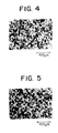
- Figs 4 and 5 are photomicrographs showing the metal structure of the shell portion in a surface portion and a deep portion (50 mm from the surface) in Comparative Example 2.
- areas in a gray color are a matrix structure (primary crystal structure), and those in a black color are graphite particles.
- the metal structure of the shell portion it, a surface portion and a deep portion (50 mm from the surface) in each compound roll was quantitatively measured by an image analysis method.
- primary precipitated particles having various shapes were first converted to true circles having the same areas in the photomicrograph as those of the primary precipitated particles, and only the true circles having diameters exceeding 30 ⁇ m were counted for obtaining the average diameter of the primary precipitated particles.
- the surface of the test piece to be measured was subjected to heavy etching so that the matrix particles (primary crystals) were turned to black, and the same measurement was repeated on 20 fields in the photomicrograph. An average value of the measured results was used as an average diameter of the matrix particles.
- the matrix particles had an average diameter of 62 /1 .m in a surface portion and 85 ⁇ m in a portion as deep as 50 mm from the surface.
- the granular or worm-like graphite particles had an average diameter of 55 ⁇ m in a surface portion and 70 ⁇ m in a portion as deep as 50 mm from the surface. In the 50-mm-deep portion, the amount of the graphite particles was excessive.
- the matrix particles had an average diameter of 60 ⁇ m and 58 ⁇ m, respectively, in a surface portion, and 70 ⁇ m and 68 ⁇ m. respectively, in a portion as deep as 50 mm from the surface.
- the granular or worm-like graphite particles had an average diameter of 42 /1 .m and 39 ⁇ m, respectively, in a surface portion, and 51 ⁇ m and 47 ⁇ m, respectively, in a portion as deep as 50 mm from the surface.
- the shell portion is formed by a fine and uniform metal structure from a surface to a deep portion.
- the high-alloy cast iron material was used for the shell portion hut it should be noted that any other cast iron may be used as long as fine and uniform metal structures can be obtained by a centrifugal casting method.
- the compound roll of the present invention comprises a shell portion having a fine and uniform metal structure free from cast defects, segregation, etc. Therefore, it can be used for producing high-quality rolled steel sheets by hot rolling or cold rolling, and the amounts of the rolled steel sheets per a unit consumption of the shell portion of the compound roll can be increased.
Applications Claiming Priority (2)
| Application Number | Priority Date | Filing Date | Title |
|---|---|---|---|
| JP3167304A JPH04350143A (ja) | 1990-07-09 | 1991-07-09 | 圧延用ロールおよびその製造方法 |
| JP167304/91 | 1991-07-09 |
Publications (2)
| Publication Number | Publication Date |
|---|---|
| EP0525932A1 true EP0525932A1 (fr) | 1993-02-03 |
| EP0525932B1 EP0525932B1 (fr) | 1996-09-11 |
Family
ID=15847272
Family Applications (1)
| Application Number | Title | Priority Date | Filing Date |
|---|---|---|---|
| EP92301946A Expired - Lifetime EP0525932B1 (fr) | 1991-07-09 | 1992-03-06 | Cylindre composite et procédé pour sa fabrication |
Country Status (4)
| Country | Link |
|---|---|
| US (1) | US5305522A (fr) |
| EP (1) | EP0525932B1 (fr) |
| KR (1) | KR960006587B1 (fr) |
| DE (1) | DE69213608T2 (fr) |
Cited By (4)
| Publication number | Priority date | Publication date | Assignee | Title |
|---|---|---|---|---|
| EP0871784A4 (fr) * | 1995-06-06 | 1998-10-21 | ||
| WO1999058761A1 (fr) * | 1998-05-14 | 1999-11-18 | Valmet Corporation | Rouleau pour papier/carton ou machine d'appret et procede de fabrication d'une virole |
| WO2000065118A1 (fr) * | 1999-04-22 | 2000-11-02 | Eisenwerk Sulzau-Werfen R. & E. Weinberger Ag | Materiau de moulage pour cylindre indefini muni d'une partie de bandage et procede permettant de le produire |
| EP2660344A1 (fr) * | 2012-05-04 | 2013-11-06 | Akers AB | Rouleau de moulage par centrifugation pour les derniers socles de finition dans des laminoirs de tôles chaudes |
Families Citing this family (13)
| Publication number | Priority date | Publication date | Assignee | Title |
|---|---|---|---|---|
| AU650271B2 (en) * | 1990-06-13 | 1994-06-16 | Nippon Steel Corporation | Composite roll for use in rolling and manufacture thereof |
| US5355932A (en) * | 1992-03-06 | 1994-10-18 | Hitachi Metals, Ltd. | Method of producing a compound roll |
| EP0704393B1 (fr) * | 1994-09-28 | 1998-10-21 | Mannesmann Dematic Rapistan Corp. | Système de branchement pour convoyeurs |
| US5813962A (en) * | 1996-06-28 | 1998-09-29 | Kawasaki Steel Corporation | Forged roll for rolling a seamless steel pipe |
| BRPI0417058A (pt) * | 2003-12-01 | 2007-03-27 | Sms Demag Ag | acionador de bobina com rolos acionadores com camisa fundida |
| JP4799004B2 (ja) * | 2004-03-08 | 2011-10-19 | 株式会社小松製作所 | Fe系シール摺動部材及びその製造方法 |
| US8156651B2 (en) * | 2004-09-13 | 2012-04-17 | Hitachi Metals, Ltd. | Centrifugally cast external layer for rolling roll and method for manufacture thereof |
| JP5024051B2 (ja) * | 2005-12-28 | 2012-09-12 | 日立金属株式会社 | 遠心鋳造複合ロール |
| DE112007003350A5 (de) * | 2007-02-20 | 2010-02-25 | Siemens Aktiengesellschaft | Bauteil, Vorrichtung zur Verschleißkontrolle für ein Bauteil und Verfahren zur Instandsetzung eines Bauteils |
| CN103813864B (zh) * | 2011-09-21 | 2016-04-13 | 日立金属株式会社 | 热轧用离心铸造复合辊及其制造方法 |
| SI2740552T1 (sl) * | 2012-04-02 | 2016-07-29 | Hitachi Metals, Ltd. | Centrifugalno ulit kompozitni valj in postopek za proizvodnjo le-tega |
| WO2015045720A1 (fr) * | 2013-09-25 | 2015-04-02 | 日立金属株式会社 | Rouleau composite moulé par centrifugation et son procédé de fabrication |
| US10047417B2 (en) * | 2015-03-11 | 2018-08-14 | Aktiebolaget Skf | Continuous caster roll for a continuous casting machine |
Citations (1)
| Publication number | Priority date | Publication date | Assignee | Title |
|---|---|---|---|---|
| US4726417A (en) * | 1986-09-12 | 1988-02-23 | Hitachi Metals, Ltd. | Adamite compound roll |
Family Cites Families (13)
| Publication number | Priority date | Publication date | Assignee | Title |
|---|---|---|---|---|
| JPS5033021A (fr) * | 1973-07-21 | 1975-03-31 | ||
| JPS5415001B2 (fr) * | 1974-06-12 | 1979-06-12 | ||
| JPS5641050A (en) * | 1979-09-11 | 1981-04-17 | Kubota Ltd | Production of roll for rolling |
| JPS5830382B2 (ja) * | 1979-10-26 | 1983-06-29 | 株式会社クボタ | 高クロムワ−クロ−ル |
| FR2493191A1 (fr) * | 1980-10-31 | 1982-05-07 | Usinor | Cydindre de laminage a froid fabrique par coulee et son procede de fabrication |
| JPS5791861A (en) * | 1980-11-28 | 1982-06-08 | Kubota Ltd | Production of centrifugally cast work roll |
| CH667285A5 (de) * | 1986-02-14 | 1988-09-30 | Sulzer Ag | Walze mit harter mantelflaeche. |
| US4721153A (en) * | 1986-09-12 | 1988-01-26 | Hitachi Metals, Inc. | High-chromium compound roll |
| DE3882636T2 (de) * | 1987-03-24 | 1993-11-04 | Hitachi Metals Ltd | Verschleissfeste verbundwalze und verfahren zu ihrer herstellung. |
| US4861549A (en) * | 1988-02-18 | 1989-08-29 | National Forge Company | Roller caster shell steel |
| JPH01254363A (ja) * | 1988-04-05 | 1989-10-11 | Kawasaki Steel Corp | 圧延用ロールの製造方法 |
| JPH02181191A (ja) * | 1989-01-05 | 1990-07-13 | Nec Corp | 文字表示装置 |
| US5053284A (en) * | 1989-02-02 | 1991-10-01 | Hitachi Metals, Ltd. | Wear-resistant compound roll |
-
1992
- 1992-03-06 DE DE69213608T patent/DE69213608T2/de not_active Expired - Lifetime
- 1992-03-06 EP EP92301946A patent/EP0525932B1/fr not_active Expired - Lifetime
- 1992-03-06 US US07/847,508 patent/US5305522A/en not_active Expired - Lifetime
- 1992-03-07 KR KR1019920003765A patent/KR960006587B1/ko not_active IP Right Cessation
Patent Citations (1)
| Publication number | Priority date | Publication date | Assignee | Title |
|---|---|---|---|---|
| US4726417A (en) * | 1986-09-12 | 1988-02-23 | Hitachi Metals, Ltd. | Adamite compound roll |
Non-Patent Citations (2)
| Title |
|---|
| PATENT ABSTRACTS OF JAPAN, unexamined applications, C field, vol. 9, no. 145, June 20, 1985 THE PATENT OFFICE JAPANESE GOVERNMENT page 161 C 287 * |
| PATENT ABSTRACTS OF JAPAN, unexamined applications, M field, vol. 11, no. 347, November 13, 1987 THE PATENT OFFICE JAPANESE GOVERNMENT page 97 M 641 * |
Cited By (10)
| Publication number | Priority date | Publication date | Assignee | Title |
|---|---|---|---|---|
| EP0871784A4 (fr) * | 1995-06-06 | 1998-10-21 | ||
| EP0871784A1 (fr) * | 1995-06-06 | 1998-10-21 | Akers International Ab | Cylindre en fonte en coquille indefinie produit par addition de niobium |
| US6013141A (en) * | 1995-06-06 | 2000-01-11 | Akers International Ab | Cast iron indefinite chill roll produced by the addition of niobium |
| WO1999058761A1 (fr) * | 1998-05-14 | 1999-11-18 | Valmet Corporation | Rouleau pour papier/carton ou machine d'appret et procede de fabrication d'une virole |
| WO2000065118A1 (fr) * | 1999-04-22 | 2000-11-02 | Eisenwerk Sulzau-Werfen R. & E. Weinberger Ag | Materiau de moulage pour cylindre indefini muni d'une partie de bandage et procede permettant de le produire |
| US6805757B1 (en) | 1999-04-22 | 2004-10-19 | Eisenwerk Sulzau-Werfen R. & E. Weinberger Ag | Casting material for indefinite rollers with sleeve part and method for producing the same |
| KR100497110B1 (ko) * | 1999-04-22 | 2005-06-29 | 아이젠베르크 슐차우 - 베르펜 에르. 운트 에. 바인베르거 아게 | 부정 롤러의 작업 영역용 합금 주물 재료와, 상기 주물 재료의 제조 및 가공 방법과, 부정 탠덤 롤러 |
| CZ299776B6 (cs) * | 1999-04-22 | 2008-11-19 | Eisenwerk Sulzau-Werfen R. & E. Weinberger Ag | Zpusob výroby a zpracování legovaného litého materiálu pro pracovní oblast válcu z materiálu nedefinované struktury, litý materiál a sdružený válec zmateriálu nedefinované struktury |
| EP2660344A1 (fr) * | 2012-05-04 | 2013-11-06 | Akers AB | Rouleau de moulage par centrifugation pour les derniers socles de finition dans des laminoirs de tôles chaudes |
| WO2013164469A1 (fr) * | 2012-05-04 | 2013-11-07 | Åkers AB | Cylindre de laminoir moulé par centrifugation pour dernières cages finisseuses dans des laminoirs à bandes à chaud |
Also Published As
| Publication number | Publication date |
|---|---|
| EP0525932B1 (fr) | 1996-09-11 |
| KR930002020A (ko) | 1993-02-22 |
| DE69213608D1 (de) | 1996-10-17 |
| DE69213608T2 (de) | 1997-02-06 |
| KR960006587B1 (ko) | 1996-05-20 |
| US5305522A (en) | 1994-04-26 |
Similar Documents
| Publication | Publication Date | Title |
|---|---|---|
| US5484372A (en) | Compound roll and method of producing same | |
| US5305522A (en) | Method of producing a compound roll | |
| EP2706128B1 (fr) | Rouleau de laminoir composite coulé de façon centrifuge et son procédé de fabrication | |
| EP3050636B1 (fr) | Cylindre composite de laminage à chaud coulé par centrifugation | |
| EP3050637B1 (fr) | Cylindre composite coulé par centrifugation pour laminage à chaud | |
| EP3437747B1 (fr) | Cylindre de laminoir composite | |
| CN105121044A (zh) | 离心铸造制热轧用复合辊 | |
| EP0430241A1 (fr) | Cylindre de laminoir composite bimétallique résistant à l'usure | |
| JPH02258949A (ja) | 耐摩耗複合ロール | |
| KR100497110B1 (ko) | 부정 롤러의 작업 영역용 합금 주물 재료와, 상기 주물 재료의 제조 및 가공 방법과, 부정 탠덤 롤러 | |
| EP0871784B1 (fr) | Cylindre en fonte en coquille indefinie produit par addition de niobium | |
| JP2000239779A (ja) | 遠心鋳造製圧延ロール用外層材、圧延ロールおよびその製造方法 | |
| JP2001150007A (ja) | 圧延ロール用外層及び圧延ロール | |
| JP3206093B2 (ja) | 圧延用ロールおよびその製造方法 | |
| JP2686207B2 (ja) | 圧延用ロール材 | |
| JP2778896B2 (ja) | 圧延用ロール及びその製造方法 | |
| JP6852722B2 (ja) | 熱間圧延粗圧延スタンド用ワークロール | |
| JP7158312B2 (ja) | 熱間圧延用ロール外層材および熱間圧延用複合ロールならびに熱間圧延用ロール外層材の製造方法 | |
| JPH04191347A (ja) | 組立式圧延ロール用中空スリーブ材 | |
| JP3211348B2 (ja) | 圧延用ロールおよびその製造方法 | |
| JPH09285855A (ja) | Ni含有鋼の製造方法 | |
| US20020096309A1 (en) | Gradient material molded body | |
| JPH0641676A (ja) | 耐摩耗性複合ロール | |
| JPH04350143A (ja) | 圧延用ロールおよびその製造方法 | |
| JPH0776407B2 (ja) | 耐摩耗性および耐肌荒性に優れた黒鉛を有する高クロム鋳鉄材 |
Legal Events
| Date | Code | Title | Description |
|---|---|---|---|
| PUAI | Public reference made under article 153(3) epc to a published international application that has entered the european phase |
Free format text: ORIGINAL CODE: 0009012 |
|
| AK | Designated contracting states |
Kind code of ref document: A1 Designated state(s): DE FR GB |
|
| 17P | Request for examination filed |
Effective date: 19930306 |
|
| 17Q | First examination report despatched |
Effective date: 19950712 |
|
| GRAH | Despatch of communication of intention to grant a patent |
Free format text: ORIGINAL CODE: EPIDOS IGRA |
|
| GRAH | Despatch of communication of intention to grant a patent |
Free format text: ORIGINAL CODE: EPIDOS IGRA |
|
| GRAA | (expected) grant |
Free format text: ORIGINAL CODE: 0009210 |
|
| AK | Designated contracting states |
Kind code of ref document: B1 Designated state(s): DE FR GB |
|
| ET | Fr: translation filed | ||
| REF | Corresponds to: |
Ref document number: 69213608 Country of ref document: DE Date of ref document: 19961017 |
|
| PLBE | No opposition filed within time limit |
Free format text: ORIGINAL CODE: 0009261 |
|
| STAA | Information on the status of an ep patent application or granted ep patent |
Free format text: STATUS: NO OPPOSITION FILED WITHIN TIME LIMIT |
|
| 26N | No opposition filed | ||
| REG | Reference to a national code |
Ref country code: GB Ref legal event code: IF02 |
|
| PGFP | Annual fee paid to national office [announced via postgrant information from national office to epo] |
Ref country code: FR Payment date: 20100324 Year of fee payment: 19 |
|
| PGFP | Annual fee paid to national office [announced via postgrant information from national office to epo] |
Ref country code: GB Payment date: 20100303 Year of fee payment: 19 |
|
| PGFP | Annual fee paid to national office [announced via postgrant information from national office to epo] |
Ref country code: DE Payment date: 20100318 Year of fee payment: 19 |
|
| GBPC | Gb: european patent ceased through non-payment of renewal fee |
Effective date: 20110306 |
|
| REG | Reference to a national code |
Ref country code: FR Ref legal event code: ST Effective date: 20111130 |
|
| PG25 | Lapsed in a contracting state [announced via postgrant information from national office to epo] |
Ref country code: FR Free format text: LAPSE BECAUSE OF NON-PAYMENT OF DUE FEES Effective date: 20110331 Ref country code: DE Free format text: LAPSE BECAUSE OF NON-PAYMENT OF DUE FEES Effective date: 20111001 |
|
| REG | Reference to a national code |
Ref country code: DE Ref legal event code: R119 Ref document number: 69213608 Country of ref document: DE Effective date: 20111001 |
|
| PG25 | Lapsed in a contracting state [announced via postgrant information from national office to epo] |
Ref country code: GB Free format text: LAPSE BECAUSE OF NON-PAYMENT OF DUE FEES Effective date: 20110306 |