EP0525311B1 - Dispositif de soupape réglée par pression et circuit de refroidissement d'un moteur à combustion interne - Google Patents
Dispositif de soupape réglée par pression et circuit de refroidissement d'un moteur à combustion interne Download PDFInfo
- Publication number
- EP0525311B1 EP0525311B1 EP92107930A EP92107930A EP0525311B1 EP 0525311 B1 EP0525311 B1 EP 0525311B1 EP 92107930 A EP92107930 A EP 92107930A EP 92107930 A EP92107930 A EP 92107930A EP 0525311 B1 EP0525311 B1 EP 0525311B1
- Authority
- EP
- European Patent Office
- Prior art keywords
- pressure
- closing body
- low
- cooling fluid
- valve
- Prior art date
- Legal status (The legal status is an assumption and is not a legal conclusion. Google has not performed a legal analysis and makes no representation as to the accuracy of the status listed.)
- Expired - Lifetime
Links
Images


Classifications
-
- F—MECHANICAL ENGINEERING; LIGHTING; HEATING; WEAPONS; BLASTING
- F01—MACHINES OR ENGINES IN GENERAL; ENGINE PLANTS IN GENERAL; STEAM ENGINES
- F01P—COOLING OF MACHINES OR ENGINES IN GENERAL; COOLING OF INTERNAL-COMBUSTION ENGINES
- F01P11/00—Component parts, details, or accessories not provided for in, or of interest apart from, groups F01P1/00 - F01P9/00
- F01P11/14—Indicating devices; Other safety devices
- F01P11/18—Indicating devices; Other safety devices concerning coolant pressure, coolant flow, or liquid-coolant level
-
- F—MECHANICAL ENGINEERING; LIGHTING; HEATING; WEAPONS; BLASTING
- F01—MACHINES OR ENGINES IN GENERAL; ENGINE PLANTS IN GENERAL; STEAM ENGINES
- F01P—COOLING OF MACHINES OR ENGINES IN GENERAL; COOLING OF INTERNAL-COMBUSTION ENGINES
- F01P11/00—Component parts, details, or accessories not provided for in, or of interest apart from, groups F01P1/00 - F01P9/00
- F01P11/02—Liquid-coolant filling, overflow, venting, or draining devices
- F01P11/0204—Filling
- F01P11/0209—Closure caps
- F01P11/0238—Closure caps with overpressure valves or vent valves
-
- F—MECHANICAL ENGINEERING; LIGHTING; HEATING; WEAPONS; BLASTING
- F01—MACHINES OR ENGINES IN GENERAL; ENGINE PLANTS IN GENERAL; STEAM ENGINES
- F01P—COOLING OF MACHINES OR ENGINES IN GENERAL; COOLING OF INTERNAL-COMBUSTION ENGINES
- F01P2025/00—Measuring
- F01P2025/70—Level
Definitions
- the invention relates to a pressure-controlled valve device with switchable opening pressure to the coolant circuit of an internal combustion engine for in particular a motor vehicle according to the preamble of patent claim 1.
- the pressure relief valve in the float is only subjected to a relatively low closing force, this closing force being the difference between the opening pressure of the pressure relief valve located outside the float and that for the one in the coolant tank corresponds to the specified high pressure at engine standstill in relation to atmosphere.
- this closing force being the difference between the opening pressure of the pressure relief valve located outside the float and that for the one in the coolant tank corresponds to the specified high pressure at engine standstill in relation to atmosphere.
- the closing pressure of the valve in the float is measured at 0.6 bar.
- high manufacturing accuracies, in particular with the closing spring are required for perfect work.
- two independent pressure relief valves each with separate valve parts, in particular separate closing springs, are also necessary.
- a pressure controlled valve device with two pressure relief valves is known.
- a first pressure relief valve is provided with a low-pressure closure body which determines the function when gas or steam is applied, and the second is provided with a high-pressure closure body which determines the function when liquid is applied.
- This valve device also has a float which is arranged such that it blocks a flow path controlled by the low-pressure closure body when the coolant level in the coolant tank rises.
- two pressure relief valves constructed independently of one another, each with separate valve parts, in particular separate closing springs, are necessary.
- a correspondingly opening check valve can be attached quite easily in the high-pressure closure body according to claim 1.
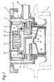
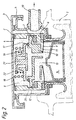
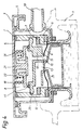
- the drawing shows the same longitudinal section of a pressure-controlled valve device, each with different valve closure body positions.
- the valve device essentially consists of a carrier part 2, which is fixed in the opening of the coolant container 1 and is covered on the outside by a cover 3.
- a valve housing 5 is clamped against the cover 3 by a plate spring 4 and is sealed in the carrier part 2 with respect to the opening in the coolant container 1.
- This housing 5 has a valve seat 6 with a seal 7 lying thereon. While the valve housing 5 seals the interior of the coolant container 1 to the atmosphere between the opening in the coolant container 1 and the valve seat 6, this housing has openings 8 to the atmosphere in its remaining area .
- the closure body 10 is designed so that there is a low-pressure flow path 11 between the sealing flange 12, the membrane 9 and the valve housing 5, which is connected via an opening 13 to the interior of the coolant container.
- This opening 13 can be closed by a float 14 which can be raised by the cooling liquid.
- the low-pressure closure body 10 has a high-pressure flow path 15 leading into the interior of the liquid container, which can be closed to the atmosphere by means of a plate-shaped high-pressure closure.
- a high-pressure closure body 16 lies against the sealing flange 12 in a sealing manner via a molded-on annular web 17 via a seal.
- the closing pressure for the two closure bodies 10 and 16 is introduced onto the high-pressure closure body 16 by a compression spring 18 supported on the cover 3.
- valve device This operation of the valve device is achieved in that the resulting pressure forces triggering an opening of the closure bodies 10 and 16 are designed by appropriate design of the pressure active surfaces of the two closure bodies 10, 16 so that when the float is not raised, the low-pressure closure body 10 opens first, specifically at Reaching the opening pressure set for this.
- This state is shown in Fig. 2, in which the sealing flange 12 of the low-pressure closure body 10 is lifted from the seal 7 of the valve seat 6 of the valve housing.
- the float 14 keeps access to the free space 11 within the closure body 10 open, so that the open position of the closure body 10 safely ensures a free outflow of gas or coolant into a valve outlet 19.
- the float 14 is raised and the opening 13 is closed to the flow path 11. This condition occurs after a hot engine is stopped.
- the closure of the opening 13 leads to the fact that no more flow can take place via the sealing flange 12 of the low-pressure closure body 10.
- the active surfaces of the closure body 10 which are exposed to the internal pressure of the liquid container are designed such that, before the high-pressure closure body 16 is opened, the low-pressure closure body 10 first assumes a defined final open position by abutment of its sealing flange 12 against a stop 20. While the closure body 10 is on the way there in the operating state according to FIG. 4, it has reached this end position in the operating state according to the illustration in FIG. 5. If the internal pressure of the liquid container exceeds the closing pressure set for the high-pressure closure body, the latter opens when the low-pressure closure body 10 abuts the stop 20.
- the low-pressure closure body 10 In the operating state shown in FIG. 4, the low-pressure closure body 10 is in its position which enables the high-pressure closure body 16 to be opened by contact with the stop 20.
Landscapes
- Engineering & Computer Science (AREA)
- Chemical & Material Sciences (AREA)
- Combustion & Propulsion (AREA)
- Mechanical Engineering (AREA)
- General Engineering & Computer Science (AREA)
- Safety Valves (AREA)
- Control Of Fluid Pressure (AREA)
- Fluid-Driven Valves (AREA)
Claims (3)
- Dispositif à soupape commandé par pression, dont la pression d'ouverture peut être une basse pression ou une haute pression et qui est disposé dans le circuit de liquide de refroidissement d'un moteur à combustion interne, notamment pour un véhicule, ce dispositif étant sollicité en pression d'une part par de la vapeur ou du gaz se dégageant du liquide de refroidissement contenu dans le réservoir de liquide de refroidissement (1) en fonction de l'état de marche du moteur ou d'autre part par le liquide de refroidissement proprement dit et s'ouvrant quand il est sollicité par le liquide à une pression plus grande que lors d'une sollicitation par du gaz ou de la vapeur,
le dispositif comportant:- un élément de fermeture basse pression (10) opérant en cas de sollicitation par du gaz ou de la vapeur et poussé par ressort dans la position de fermeture.- un élément de fermeture haute pression (16) opérant en cas de sollicitation par le liquide et poussé également par resssort dans la position de fermeture,- un flotteur (14), qui est déposé de telle sorte que, lors d'une montée du niveau de liquide de refroidissement dans le réservoir (1), il ferme un passage d'écoulement (13, 11) commandé en fonction du débit par l'élément de fermeture basse pression (10), la surface active résultant, qui est prépondérante pour que l'ouverture de l'élément de fermeture basse pression (10) s'effectue sous la pression régnant dans le réservoir de liquide de refroidissement, (1), étant plus grande, dans tous les états de marche, que celle produisant une ouverture de l'élément de fermeture haute pression (16),
dispositif caractérisé en ce que :- l'élément de fermeture basse pression (10) forme le support de l'élément de fermeture haute pression (16).- l'élément de fermeture basse pression (10) est traversé par un passage d'écoulement (15) conduisant à l'élément de fermeture haute pression (16) et qui est ouvert dans tous les états de marche,- la pression de fermeture sollicitant les éléments de fermeture est appliqué uniquement par l'intermédiaire de l'élément de fermeture haute pression (16), et- il eut prévu pour l'élément de fermeture basse pression (10) une butée (20) qui est disposée de telle sorte que l'élément de fermeture basse pression (10) prenne une position d'ouverture définie quand l'élément de fermeture haute pression (16) est ouvert. - Dispositif à soupape commandé par pression selon la revendication 1, caractérisé en ce que l'élément de fermeture basse pression (10) comporte une collerette d'étanchéïté (12), faisant saillie radialement vers l'extérieur, l'entourant avec une forme annulaire, qui peut être appliquée de façon étanche, dans un sens opposé au sens de sortie d'écoulement de la soupape, contre un siège de soupape (6) monté en position fixe dans le corps de soupape (5) et qui est reliée, radialement vers l'extérieur et par l'intermédiaire d'un organe d'étanchéïté (membrane 9) pratiquement exempt de forces de réaction, de façon étanche au gaz avec le corps de soupape (5), un passage d'écoulement basse pression (11) étant formé entre la membrane (9) et la collerette d'étanchéïté (12), débouchant dans le réservoir de liquide de refroidissement (1) et étant séparé de l'intérieur de ce réservoir (1) quand le flotteur (14) est relevé, et en ce que l'élément de fermeture basse pression (10) comporte en outre un passage d'écoulement haute pression (15) reliant le réservoir de liquide de refroidissement (1) avec l'atmosphère quand l'élément de fermeture haute pression (16) est ouvert.
- Dispositif à soupape commandé par pression selon la revendication 1 ou 2, caractérisé en ce que l'élément de fermeture haute pression (16) est pourvu d'un clapet anti-retour (21) s'ouvrant de l'atmosphère vers l'extérieur du réservoir de liquide de refroidissement (1).
Applications Claiming Priority (2)
| Application Number | Priority Date | Filing Date | Title |
|---|---|---|---|
| DE4124182 | 1991-07-20 | ||
| DE4124182A DE4124182C1 (fr) | 1991-07-20 | 1991-07-20 |
Publications (2)
| Publication Number | Publication Date |
|---|---|
| EP0525311A1 EP0525311A1 (fr) | 1993-02-03 |
| EP0525311B1 true EP0525311B1 (fr) | 1994-08-24 |
Family
ID=6436685
Family Applications (1)
| Application Number | Title | Priority Date | Filing Date |
|---|---|---|---|
| EP92107930A Expired - Lifetime EP0525311B1 (fr) | 1991-07-20 | 1992-05-12 | Dispositif de soupape réglée par pression et circuit de refroidissement d'un moteur à combustion interne |
Country Status (4)
| Country | Link |
|---|---|
| US (1) | US5197440A (fr) |
| EP (1) | EP0525311B1 (fr) |
| DE (1) | DE4124182C1 (fr) |
| ES (1) | ES2063546T3 (fr) |
Families Citing this family (9)
| Publication number | Priority date | Publication date | Assignee | Title |
|---|---|---|---|---|
| DE4220631C1 (en) * | 1992-06-24 | 1993-03-11 | Mercedes-Benz Aktiengesellschaft, 7000 Stuttgart, De | Valve arrangement for cooling circuit of IC engine - has at least two excess pressure valves and switch valve for change of pressure between excess pressure valves |
| DE4233038C1 (de) * | 1992-10-01 | 1993-11-25 | Daimler Benz Ag | Überdrucksicherung für einen Kühlmittelkreislauf |
| ES2121626T3 (es) * | 1994-06-01 | 1998-12-01 | Heinrich Reutter | Tapa de cierre fijable a un manguito de deposito. |
| FR2740830B1 (fr) * | 1995-11-08 | 1997-12-05 | Journee Paul Sa | Bouchon de circuit de refroidissement de vehicule automobile muni d'un dispositif de degazage |
| DE29617824U1 (de) * | 1996-10-14 | 1997-02-13 | Kuhlmann Guenter | Kühlkreislauf-Sicherheitsvorrichtung |
| DE19642114A1 (de) * | 1996-10-14 | 1997-03-27 | Guenter Kuhlmann | Kühlkreislauf-Sicherheitsventil mit "hot stop"-Ventil für PKW- und LKW-Motoren |
| DE19753592A1 (de) * | 1997-12-03 | 1999-06-10 | Heinrich Reutter | Verschlußdeckel |
| US6237682B1 (en) * | 1999-04-30 | 2001-05-29 | Motorola, Inc. | Cooling module including a pressure relief mechanism |
| KR101459949B1 (ko) * | 2013-09-26 | 2014-11-07 | 현대자동차주식회사 | 냉각수 비산 방지 타입 서지탱크 |
Family Cites Families (8)
| Publication number | Priority date | Publication date | Assignee | Title |
|---|---|---|---|---|
| US2732971A (en) * | 1956-01-31 | Radiator caps | ||
| US1541073A (en) * | 1924-09-12 | 1925-06-09 | Alfred L Sohm | Indicator |
| FR1245326A (fr) * | 1960-01-15 | 1960-11-04 | Perfectionnements aux bouchons de radiateurs à circulation d'eau sous pression | |
| JPS5417900B2 (fr) * | 1974-03-14 | 1979-07-03 | ||
| DE3436702A1 (de) * | 1984-10-06 | 1986-04-10 | Süddeutsche Kühlerfabrik Julius Fr. Behr GmbH & Co KG, 7000 Stuttgart | Vorrichtung zum absichern des kuehlmittelkreislaufs eines verbrennungsmotors |
| DE3439554A1 (de) * | 1984-10-29 | 1986-04-30 | Bayerische Motoren Werke AG, 8000 München | Drucksteuervorrichtung fuer den kuehlkreis von brennkraftmaschinen |
| CA1276011C (fr) * | 1986-02-20 | 1990-11-06 | Nippondenso Co., Ltd. | Radiateur pour l'automobile |
| FR2614071A1 (fr) * | 1987-04-16 | 1988-10-21 | Chausson Usines Sa | Procede pour la regulation du circuit de refroidissement d'un moteur thermique et bouchon pour sa mise en oeuvre |
-
1991
- 1991-07-20 DE DE4124182A patent/DE4124182C1/de not_active Expired - Lifetime
-
1992
- 1992-05-12 EP EP92107930A patent/EP0525311B1/fr not_active Expired - Lifetime
- 1992-05-12 ES ES92107930T patent/ES2063546T3/es not_active Expired - Lifetime
- 1992-07-02 US US07/907,529 patent/US5197440A/en not_active Expired - Fee Related
Also Published As
| Publication number | Publication date |
|---|---|
| ES2063546T3 (es) | 1995-01-01 |
| DE4124182C1 (fr) | 1992-06-04 |
| EP0525311A1 (fr) | 1993-02-03 |
| US5197440A (en) | 1993-03-30 |
Similar Documents
| Publication | Publication Date | Title |
|---|---|---|
| EP1072556B1 (fr) | Système de soutirage pour pompe à essence | |
| DE2416007C3 (de) | Überdruckventil im Kühlmantel seewassergekühlter Brennkraftmaschinen | |
| EP1216740A1 (fr) | Filtre pour liquides | |
| EP0645343A1 (fr) | Vanne à clapet pilote pour stations d'essence | |
| EP0525311B1 (fr) | Dispositif de soupape réglée par pression et circuit de refroidissement d'un moteur à combustion interne | |
| EP0648965A1 (fr) | Module pour vanne de sécurité à membrane destinée au montage dans un corps de vanne | |
| DE1297936B (de) | Kuehlerverschlusskappe | |
| DE2528932A1 (de) | Filteranordnung | |
| DE1209103B (de) | Auswechselbarer OElfilter | |
| DE3204766A1 (de) | Kuehlgeblaeseeinheit fuer eine brennkraftmaschine | |
| DE102015119250B4 (de) | Verbrennungsschutzabdeckung, die mit einem unter druck setzbaren kühlmitteltank gekoppelt ist, und unter druck setzbare kühlmitteltankanordnung, die dieselbe aufweist | |
| WO2002075143A1 (fr) | Electrovanne | |
| EP1912718A1 (fr) | Ensemble filtre a liquides | |
| DE102015109691A1 (de) | Entlüftungsventil zur Verwendung in einem Kühlsystem eines Kraftfahrzeugs | |
| EP1036261B1 (fr) | Couvercle de fermeture | |
| EP0360252B1 (fr) | Couvercle de fermeture pour l'orifice de remplissage d'un réservoir à réfrigérant dans des systèmes de refroidissement de véhicules automobiles | |
| DE7504574U (de) | Schmierölfilter fürXraftfahrzeug-Brennkraftmaschinen | |
| DE2320260A1 (de) | Foerderbegrenzungsventil fuer kuehleinrichtungen | |
| EP1020647B1 (fr) | Soupape à plaque | |
| EP0634529B1 (fr) | Disconnecteur de tuyau | |
| DE19852156C1 (de) | Vorrichtung zur Abführung von gasförmigen und flüssigen Medien | |
| DE19814744A1 (de) | Druckregelventil | |
| DE3404189A1 (de) | Von einem regelbaren elektromagnet betaetigtes hydraulisches ventil | |
| DE3102828A1 (de) | Berstfolien-sicherheitsventil | |
| DE1550468A1 (de) | Drucksteuerventil |
Legal Events
| Date | Code | Title | Description |
|---|---|---|---|
| PUAI | Public reference made under article 153(3) epc to a published international application that has entered the european phase |
Free format text: ORIGINAL CODE: 0009012 |
|
| 17P | Request for examination filed |
Effective date: 19921023 |
|
| AK | Designated contracting states |
Kind code of ref document: A1 Designated state(s): ES FR GB IT SE |
|
| 17Q | First examination report despatched |
Effective date: 19931028 |
|
| GRAA | (expected) grant |
Free format text: ORIGINAL CODE: 0009210 |
|
| ITF | It: translation for a ep patent filed |
Owner name: BARZANO' E ZANARDO ROMA S.P.A. |
|
| AK | Designated contracting states |
Kind code of ref document: B1 Designated state(s): ES FR GB IT SE |
|
| GBT | Gb: translation of ep patent filed (gb section 77(6)(a)/1977) |
Effective date: 19940927 |
|
| ET | Fr: translation filed | ||
| REG | Reference to a national code |
Ref country code: ES Ref legal event code: FG2A Ref document number: 2063546 Country of ref document: ES Kind code of ref document: T3 |
|
| EAL | Se: european patent in force in sweden |
Ref document number: 92107930.7 |
|
| PLBE | No opposition filed within time limit |
Free format text: ORIGINAL CODE: 0009261 |
|
| STAA | Information on the status of an ep patent application or granted ep patent |
Free format text: STATUS: NO OPPOSITION FILED WITHIN TIME LIMIT |
|
| 26N | No opposition filed | ||
| REG | Reference to a national code |
Ref country code: FR Ref legal event code: TP |
|
| REG | Reference to a national code |
Ref country code: GB Ref legal event code: 732E |
|
| REG | Reference to a national code |
Ref country code: GB Ref legal event code: 732E |
|
| PGFP | Annual fee paid to national office [announced via postgrant information from national office to epo] |
Ref country code: GB Payment date: 20010412 Year of fee payment: 10 |
|
| PGFP | Annual fee paid to national office [announced via postgrant information from national office to epo] |
Ref country code: SE Payment date: 20010503 Year of fee payment: 10 |
|
| PGFP | Annual fee paid to national office [announced via postgrant information from national office to epo] |
Ref country code: FR Payment date: 20010507 Year of fee payment: 10 |
|
| PGFP | Annual fee paid to national office [announced via postgrant information from national office to epo] |
Ref country code: ES Payment date: 20010514 Year of fee payment: 10 |
|
| REG | Reference to a national code |
Ref country code: GB Ref legal event code: IF02 |
|
| PG25 | Lapsed in a contracting state [announced via postgrant information from national office to epo] |
Ref country code: GB Free format text: LAPSE BECAUSE OF NON-PAYMENT OF DUE FEES Effective date: 20020512 |
|
| PG25 | Lapsed in a contracting state [announced via postgrant information from national office to epo] |
Ref country code: SE Free format text: LAPSE BECAUSE OF NON-PAYMENT OF DUE FEES Effective date: 20020513 Ref country code: ES Free format text: LAPSE BECAUSE OF NON-PAYMENT OF DUE FEES Effective date: 20020513 |
|
| GBPC | Gb: european patent ceased through non-payment of renewal fee |
Effective date: 20020512 |
|
| EUG | Se: european patent has lapsed | ||
| PG25 | Lapsed in a contracting state [announced via postgrant information from national office to epo] |
Ref country code: FR Free format text: LAPSE BECAUSE OF NON-PAYMENT OF DUE FEES Effective date: 20030131 |
|
| REG | Reference to a national code |
Ref country code: FR Ref legal event code: ST |
|
| REG | Reference to a national code |
Ref country code: ES Ref legal event code: FD2A Effective date: 20030611 |
|
| PG25 | Lapsed in a contracting state [announced via postgrant information from national office to epo] |
Ref country code: IT Free format text: LAPSE BECAUSE OF NON-PAYMENT OF DUE FEES;WARNING: LAPSES OF ITALIAN PATENTS WITH EFFECTIVE DATE BEFORE 2007 MAY HAVE OCCURRED AT ANY TIME BEFORE 2007. THE CORRECT EFFECTIVE DATE MAY BE DIFFERENT FROM THE ONE RECORDED. Effective date: 20050512 |