EP0525304B1 - Selbstschutz-Werfereinrichtung - Google Patents
Selbstschutz-Werfereinrichtung Download PDFInfo
- Publication number
- EP0525304B1 EP0525304B1 EP92106651A EP92106651A EP0525304B1 EP 0525304 B1 EP0525304 B1 EP 0525304B1 EP 92106651 A EP92106651 A EP 92106651A EP 92106651 A EP92106651 A EP 92106651A EP 0525304 B1 EP0525304 B1 EP 0525304B1
- Authority
- EP
- European Patent Office
- Prior art keywords
- magazine
- carrier
- shoe
- baseplate
- base plate
- Prior art date
- Legal status (The legal status is an assumption and is not a legal conclusion. Google has not performed a legal analysis and makes no representation as to the accuracy of the status listed.)
- Expired - Lifetime
Links
- 230000001939 inductive effect Effects 0.000 claims description 9
- 238000010276 construction Methods 0.000 claims 1
- 239000013536 elastomeric material Substances 0.000 claims 1
- 238000010304 firing Methods 0.000 description 6
- 238000003780 insertion Methods 0.000 description 5
- 230000037431 insertion Effects 0.000 description 5
- 239000000969 carrier Substances 0.000 description 4
- 239000013013 elastic material Substances 0.000 description 4
- 230000005540 biological transmission Effects 0.000 description 3
- 230000006378 damage Effects 0.000 description 3
- 239000002184 metal Substances 0.000 description 3
- 239000003380 propellant Substances 0.000 description 3
- 239000006096 absorbing agent Substances 0.000 description 2
- 238000011109 contamination Methods 0.000 description 2
- 239000000463 material Substances 0.000 description 2
- 238000000034 method Methods 0.000 description 2
- 238000007789 sealing Methods 0.000 description 2
- 238000004088 simulation Methods 0.000 description 2
- 229910001220 stainless steel Inorganic materials 0.000 description 2
- 239000010935 stainless steel Substances 0.000 description 2
- 238000004804 winding Methods 0.000 description 2
- 238000004026 adhesive bonding Methods 0.000 description 1
- 230000002411 adverse Effects 0.000 description 1
- 230000000295 complement effect Effects 0.000 description 1
- 230000001419 dependent effect Effects 0.000 description 1
- 238000001514 detection method Methods 0.000 description 1
- 230000000694 effects Effects 0.000 description 1
- 239000007789 gas Substances 0.000 description 1
- 230000003993 interaction Effects 0.000 description 1
- 230000002093 peripheral effect Effects 0.000 description 1
- 239000004033 plastic Substances 0.000 description 1
- 238000003825 pressing Methods 0.000 description 1
- 238000004073 vulcanization Methods 0.000 description 1
- XLYOFNOQVPJJNP-UHFFFAOYSA-N water Substances O XLYOFNOQVPJJNP-UHFFFAOYSA-N 0.000 description 1
Images



Classifications
-
- F—MECHANICAL ENGINEERING; LIGHTING; HEATING; WEAPONS; BLASTING
- F41—WEAPONS
- F41F—APPARATUS FOR LAUNCHING PROJECTILES OR MISSILES FROM BARRELS, e.g. CANNONS; LAUNCHERS FOR ROCKETS OR TORPEDOES; HARPOON GUNS
- F41F7/00—Launching-apparatus for projecting missiles or projectiles otherwise than from barrels, e.g. using spigots
-
- F—MECHANICAL ENGINEERING; LIGHTING; HEATING; WEAPONS; BLASTING
- F41—WEAPONS
- F41F—APPARATUS FOR LAUNCHING PROJECTILES OR MISSILES FROM BARRELS, e.g. CANNONS; LAUNCHERS FOR ROCKETS OR TORPEDOES; HARPOON GUNS
- F41F1/00—Launching apparatus for projecting projectiles or missiles from barrels, e.g. cannons; Harpoon guns
- F41F1/08—Multibarrel guns, e.g. twin guns
-
- F—MECHANICAL ENGINEERING; LIGHTING; HEATING; WEAPONS; BLASTING
- F42—AMMUNITION; BLASTING
- F42B—EXPLOSIVE CHARGES, e.g. FOR BLASTING, FIREWORKS, AMMUNITION
- F42B5/00—Cartridge ammunition, e.g. separately-loaded propellant charges
- F42B5/02—Cartridges, i.e. cases with charge and missile
- F42B5/145—Cartridges, i.e. cases with charge and missile for dispensing gases, vapours, powders, particles or chemically-reactive substances
- F42B5/15—Cartridges, i.e. cases with charge and missile for dispensing gases, vapours, powders, particles or chemically-reactive substances for creating a screening or decoy effect, e.g. using radar chaff or infrared material
Definitions
- the invention relates to a self-protection launcher device with a plurality of launching tubes which can be attached to the object to be protected and contain projectiles which are combined to form a one-piece magazine block which can be inserted into a magazine carrier having a base plate and can be locked in the pushed-in state, the magazine carrier in turn on the object to be protected is attached.
- Self-protection launcher devices such as those used for protecting tanks, usually have a plurality of launch tubes, which are attached to a suitable location on the outer surface of the tank, with launchers inserted into the launch tubes, which carry a propellant charge and an active charge include, the latter being mostly a fog charge.
- the firing of the throwing bodies takes place electrically from the inside of the tank, ignition contacts being arranged in the launch tube, which are in contact with contact rings located on the throwing body jacket.
- Contactless namely inductive ignition systems are also known.
- the electrical energy received via contacts or contactlessly is used to ignite the propellant charge, in which case the hot propellant gases in turn ignite the active charge via a pyrotechnic ignition chain with a toothing.
- the attachment of the launch tubes to the respective documents can be done in generally only in a workshop with the appropriate specialists, because the electrical cables of the ignition system must also be connected accordingly. If one or more projectiles has been fired during use, then it is necessary to replace the fired projectiles, which does require a considerable amount of time. If missiles with different active loads are fired from different launch tubes, then care must be taken to reload them with the correct ammunition, which can easily lead to confusion during combat operations.
- EP-A 0 461 439 (not prepublished) relates to a self-protection launcher device which has the features mentioned at the outset.
- the base plate provided in the self-protection launcher device described there is surrounded by a sleeve-like body, into which the magazine block can be inserted in a direction perpendicular to the plane of the base plate.
- the base plate carries electrical contacts which come into engagement with the individual throwing bodies of the magazine bell. It is disadvantageous that the insertion of the magazine block into the sleeve-like body cannot take place with sufficient speed as a result of canting problems etc., particularly in combat situations. A further disadvantage is that the electrical contacts are subject to considerable contamination and, in particular in the event of a tilted insertion of the magazine block, risk of damage.
- the invention has for its object to provide a self-protection launcher device with the features mentioned above, which enables simple, fast and easy to use even with different launcher ammunition.
- the base plate of the magazine carrier has a magazine shoe for parallel insertion of a magazine foot of the magazine block parallel to the plane of the base plate, that a primary side of an inductive ignition system is used in the base plate and that the throwing bodies in each case are provided with a secondary inductive ignition system.
- the invention is based on the surprising finding that it is possible to achieve the object by, on the one hand, not using a sleeve-like body for inserting the magazine block perpendicularly to the base plate, as is provided in the self-protection launcher device according to document D1 described at the outset, but the bottom plate is provided with a magazine shoe for the lateral insertion of a magazine foot of the magazine block, which, if the magazine foot is designed to complement the shape of the magazine shoe, enables rapid, safe reloading even in combat situations.
- the inductive ignition system used which can completely dispense with contacts or their engagement between the throwing body and the base plate, ensures reliable ignition processes even if, for example, the base plate is contaminated by external influences, etc.
- DE-A 1 941 597 describes a device in which the advantageous interaction according to the invention of a base plate lying flat against the object to be protected with magazine shoe thereon or magazine shoe of the magazine block interacting therewith are not addressed.
- DE-A 3 410 467 describes a self-protection launcher device with an essentially circular weapon platform, on which a plurality of tubes are arranged in the manner of a wheel spokes, evenly distributed over the circumference of the circle.
- a combination of magazine shoe and magazine foot, as is provided in the invention, is not addressed here.
- the self-protection launcher device is used such that after the projectile has been fired, a catch located on the magazine carrier is released, the magazine is pulled out of the carrier shoe, a new magazine with loaded launch tubes is inserted into the carrier shoe and locked in place. This process is obviously quick and can be carried out without any problems even in combat situations.
- a cover block which fits into the carrier shoe and can be inserted into the carrier shoe instead of the magazine block.
- the cover block is provided with electronic circuits that simulate missile launches - for training purposes.
- the base plate designated by 10 in FIG. 1 has the function of a foundation, into which the launch-launch recoil forces are introduced and passed on to the launch platform of the object to be protected.
- the base plate 10 serves for electrical energy transmission and for this purpose contains the primary side of an inductive ignition device.
- the energy transmission parts consist of primary transformer cores 11 with associated wire windings.
- the connection of the wire windings to the power connection, namely a cable connector 12, is established by a cable harness embedded in cable channels 13.
- Sensor cores 14 provided with wire coils are used for magazine or ammunition detection.
- the cover plate 10 is attached to the launching platform of the object to be protected at 15.
- a stainless steel end cover 16 encloses the entire energy transmission part in the base plate 10.
- the attachment and sealing of the cover 16 on the base plate 10 is carried out by screws 17 and by a sealing cord 18.
- the outer contour of the base plate 10 has a fitting edge 19, via which the centering and load distribution for the magazine shoe 20 explained below takes place.
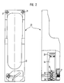
- the magazine shoe 20 already mentioned, shown in FIG. 2, has screws 21 for fastening, is centered by the base plate 10 and is supported on the base plate 10 the launch platform.
- the magnetic shoe 20 has a fork-shaped recess 22, in which, in combination with guideways, a magazine block 30 to be explained later is held by a locking mechanism consisting of the elements 23, 24, 25 and 26.
- a key 27 is used to unlock the locking mechanism 23 to 26.
- the entire locking mechanism, including the unlocking key is accommodated within the jacket contour of the magazine shoe 20 and is protected against contamination and mechanical destruction by a cover device.
- the magazine block 30 which can be inserted into the magazine shoe 20 has, according to FIG. 3, four launching tubes 31 arranged next to one another and connected to form a block, for firing throwing bodies (not shown). With 32 deformable grid pieces for receiving and locking the throwing body are designated. Recesses 33 in the foot 34 of the magazine block 30 represent snap-in points for the locking mechanism of the magazine shoe 20 described above.
- the magazine foot 34 can be introduced in a self-centering manner through the radii 35 and sliding surfaces 36 into the mentioned guideways on the magazine shoe 20.
- Sensor plates 37 in the magazine foot 34 are used to detect ammunition in cooperation with the sensors 15 of the base plate 10. Because of the symmetry of the magazine foot 34, the magazine 30 has no preferred loading direction on the protected object, that is to say that the magazine block can be 180 without adverse effects in both of it ° insert the twisted insertion positions into the magnetic shoe 20.
- a peripheral edge 38 on the muzzle side of the magazine block 30 represents an absorber for the muzzle pressure that occurs when the ammunition is fired and, moreover, serves quite generally as an energy absorber on the front of the block, for example in a drop test.
- FIG. 4 shows in perspective an arrangement with four magazine carriers 10, 20 with magazine block 30 inserted into each carrier.
- a self-protection device with four magazine blocks is suitable, for example, for attachment to one side of a vehicle, for example a tank.
- the launching platforms for the magazine carrier attachment are set in the elevation and azimuth angle according to the application requirement for the self-protection measure.
- the magazine blocks 30 are inserted into the magazine carriers.
- the magazine blocks 30 are preferably made of rubber-elastic material, which ensures elasticity in the temperature range between -40 ° C. and + 70 ° C.
- the rubber-elastic material of the magazine blocks enables the ammunition pieces mentioned to insert the ammunition into the firing tubes of the magazine block with minimal effort and to hold them in place with high clamping force, in a vibration-proof and drop-proof manner.
- magazine blocks 30 made of rubber-elastic material have the advantage that, provided they have the appropriate weight, they automatically "snap" into the locking device of the magazine shoe 20 without the need for a special latch actuation or the like. It is also important that the magazine blocks can be reduced and expanded in terms of the number of their launch tubes by adding or removing mono elements, the elements having the same geometric shape being able to be connected to one another in a simple manner, for example by gluing or if the blocks are made of rubber material - by vulcanization. Only the two outer end elements are designed differently from the central elements, but in turn have the same shape as one another. As a result, the magazine block, as already mentioned, has a two-axis symmetry and can therefore be inserted with its two upright sides into the magazine shoe.
- the ammunition firing from a magazine made of elastic material is specified by the throwing body itself, ie the throwing body is flying out of its own housing sleeve remaining in the firing tube accelerates.
- the shot can be carried out individually or magazine by magazine, with the sensors mentioned reporting where to reload, ie which magazine has to be replaced. Reloading is quick and easy;
- the magazine block is unlocked by simply pressing a button, removed from the magazine carrier and a new magazine block (loaded with throwing bodies) is inserted.
- Metal plates on the surface of the magazine blocks serve to identify the state of charge via the sensors of the base plate 10.
- the magazines can be loaded with throwing bodies of any active mass, provided that the throwing bodies have an inductive ignition system, i.e. secondary transformer cores interacting with the primary transformer cores of the base plate 10.
- Fog throwing bodies as described in EP-A-0 525 305, are particularly suitable.
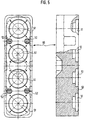
- FIG. 5 shows a cover plate 50, the dimensions and outer contour of which correspond to the foot part of the magazine shoe 30. Recesses for the engagement of the locking mechanism of the magazine shoe are provided on the outer contour.
- the material of the cover plate 50 is rubber, plastic or light metal.
- 10 secondary replacement circuits 51 (simulation device) are accommodated in accordance with the number of primary transformer cores of the base plate.
- metal disks 52 are built into its surface. The contact side of the cover plate 50 is covered by a stainless steel sheet 53.
- the cover plate 50 is intended to be used in the magazine carrier 10, 20 instead of a magazine block 30.
- the cover plate then offers mechanical protection for the guide part of the magazine shoe 20 and covers the base plate 10 with its inductive transformer cores and sensor cores, thus protecting them against dirt, water and mechanical destruction.
- the cover plate 50 with its simulation device serves the user for training purposes, ie the actual firing of projectiles from the magazine blocks 30 can be simulated realistically by the cover plate 50, which is very advantageous, for example, for the training of tank shooters.
Landscapes
- Engineering & Computer Science (AREA)
- General Engineering & Computer Science (AREA)
- Radar, Positioning & Navigation (AREA)
- Remote Sensing (AREA)
- Aiming, Guidance, Guns With A Light Source, Armor, Camouflage, And Targets (AREA)
Description
- Die Erfindung betrifft eine Selbstschutz-Werfereinrichtung mit mehreren am zu schützenden Objekt anbringbaren, Wurfkörper enthaltenden Abschußrohren, die zu einem einstückigen Magazinblock vereinigt sind, welcher in einen eine Bodenplatte aufweisenden Magazinträger einschiebbar und im eingeschobenen Zustand verriegelbar ist, wobei der Magazinträger seinerseits am zu schützenden Objekt befestigt ist.
- Selbstschutz-Werfereinrichtungen, wie sie beispielsweise zum Schutz von Panzern eingesetzt werden, weisen in der Regel eine Mehrzahl von Abschußrohren auf, die an einer geeigneten Stelle der Außenfläche des Panzers befestigt sind, wobei in die Abschußrohre Wurfkörper eingesetzt sind, die eine Treibladung und eine Wirkladung beinhalten, wobei es sich bei letzterer meist um eine Nebelladung handelt. Die Zündung der Wurfkörper erfolgt elektrisch vom Panzerinneren aus, wobei im Abschußrohr Zündkontakte angeordnet sind, die mit am Wurfkörpermantel befindlichen Kontaktringen in Berührung stehen. Bekannt sind aber auch kontaktlose, nämlich induktive Zündsysteme. Im Wurfkörper wird die über Kontakte oder kontaktlos empfangene elektrische Energie zur Zündung der Treibladung genutzt, wobei dann die heißen Treibgase ihrerseits über eine pyrotechnische Zündkette mit Verzägerungsstück die Wirkladung anzünden.
- Die Anbringung der Abschußrohre an der jeweiligen Unterlagen, also beispielsweise der Außenfläche eines Panzers, kann im allgemeinen nur in einer Werkstatt mt entsprechenden Fachleuten erfolgen, weil auch die elektrischen Leitungen des Zündsystems entsprechend angeschlossen werden müssen. Ist im Einsatz ein Abschuß von einem oder mehreren Wurfkörpern erfolgt, dann ist es erforderlich, die abgefeuerten Wurfkörper zu ersetzen, wozu doch ein nicht unbeträchtlicher Zeitaufwand notwendig ist. Werden aus verschiedenen Abschußrohren Wurfkörper unterschiedlicher Wirkladung verschossen, dann muß darauf geachtet werden, das Nachladen mit der jeweils richtigen Munition vorzunehmen, was gerade im Gefechtseinsatz leicht zu Verwechslungen führt.
- Gegenstand der EP-A 0 461 439 (nicht vorveröffentlicht) ist eine Selbstschutz-Werfereinrichtung, welche die eingangs genannten Merkmale aufweist. Die bei der dort beschriebenen Selbstschutz-Werfereinrichtung vorgesehene Bodenplatte ist von einem hülsenartigen Körper umgeben, in welchen der Magazinblock in zur Ebene der Bodenplatte senkrechter Richtung einschiebbar ist. Die Bodenplatte trägt elektrische Kontakte, die mit den einzelnen Wurfkörpern des Magazinglockes in Eingriff kommen. Ungünstig ist dabei, daß das Einschieben des Magazinblocks in den hülsenartigen Körper in Folge von Verkantungsproblemen etc. insbesondere in Gefechtsituationen nicht mit hinreichender Schnelligkeit erfolgen kann. Ferner ist nachteilig, daß die elektrischen Kontakte einen erheblichen Verschmutzungs- und, insbesondere im Falle eines verkanteten Einführens des Magazinblockes, Beschädigungsgefahr unterliegen.
- Der Erfindung liegt die Aufgabe zugrunde, eine Selbstschutz-Werfereinrichtung mit den eingangs genannten Merkmalen zu schaffen, die ein einfaches, schnelles und auch bei Verwendung unterschiedlicher Werfermunitionen problemloses Nachladen ermöglicht.
- Erfindungsgemäß wird diese Aufgabe dadurch gelöst, daß zusätzlich vorgesehen ist, daß die Bodenplatte des Magazinträgers einen Magazinschuh zum parallel zur Ebene der Bodenplatte erfolgenden seitlichen Einschieben eines Magazinfußes des Magazinblocks aufweist, daß in der Bodenplatte eine Primärseite eines induktiven Zündsystems untergebraucht ist und daß die Wurfkörper jeweils mit einem sekundären induktiven Zündsystem versehen sind.
- Besondere Ausführungsformen der Erfindung sind Gegenstand der Unteransprüche.
- Der Erfindung liegt die überraschende Erkenntnis zugrunde, daß es gelingt, die gestellte Aufgabe zu lösen, indem einerseits nicht ein hülsenartiger Körper zum zur Bodenplatte senkrechten Einschieben des Magazinblockes verwendet wird, wie er bei der eingangs beschriebenen Selbsschutz-Werfereinrichtung nach dem Dokument D1 vorgesehen ist, sondern die Bodenplatte mit einem Magazinschuh zum seitlichen Einschieben eines Magazinfußes des Magazinblockes versehen wird, wodurch, bei zweckentsprechender Ausgestaltung des Magazinfußes komplementär zur Form des Magazinschuhs, ein rasches, sicheres Nachladen auch in Gefechtssituationen ermöglicht wird. Darüberhinaus gewährleistet das verwendete induktive Zündsystem, welches auf Kontakte bzw. deren Ineingriffbringen zwischen Wurfkörper und Bodenplatte gänzlich verzichten kann, zuverlässige Zündungsvorgänge auch dann, wenn beispielsweise die Bodenplatte durch äußere Einflüsse verschmutzt ist, etc..
- Die DE-A 1 941 597 beschreibt eine Vorrichtung, bei der das erfindungsgemäße vorteilhafte Zusammenwirkung einer am zu schützenden Objekt eben anliegenden Bodenplatte mit darauf befindlichem Magazinschuh bzw. damit zusammenwirkenden Magazinschuhs des Magazinblockes nicht angesprochen sind.
- Aus der US-A 3,808,940 ist es bekannt, einen Magazinblock in Verbindung mit einem Magazinträger zu verwenden, ohne daß aber die Kombination eines Magazinschuhs mit seitlich einzuschiebendem Magazinfuß entsprechend der Erfindung erwähnt wäre.
- Die DE-A 3 410 467 beschreibt eine Selbstschutz-Werfereinrichtung mit im wesentlichen kreisförmiger Waffenplattform, auf der eine Mehrzahl von Rohren radspeichenartig auf dem Kreisumfang gleichmäßig verteilt angeordnet ist. Eine Kombination von Magazinschuh und Magazinfuß, wie sie bei der Erfindung vorgesehen ist, ist dabei nicht angesprochen.
- Aus der US-A 4,470,336 ist eine Werfereinrichtung für eine Anzahl von Wurfkörpern bekannt, die ebenfalls das erfindungsgemäße Prinzip einer schnell lösbaren Verbindung zwischen Bodenplatte bzw. Magazinschuh und Magazinträger bzw. Magazinfuß nicht erkennen läßt.
- Insgesamt wird mittels der erfindungsgemäßen Selbstschutz-Werfereinrichtung so vorgegangen, daß nach erfolgtem Abschuß der Wurfkörper eine am Magazinträger befindliche Arretierung gelöst, das Magazin aus dem Trägerschuh herausgezogen, ein neues Magazin mit geladenen Abschußrohren in den Trägerschuh eingeschoben und in diesem arretiert wird. Dieser Vorgang ist offensichtlich schnell und auch in Gefechtsituationen problemlos durchzuführen.
- Nach einer besonders zweckmäßigen weiteren Ausbildung der Erfindung ist ein Abdeckblock vorgesehen, der in den Trägerschuh einpaßt und an Stelle des Magazinblock in den Trägerschuh einschiebbar ist. Dabei ist der Abdeckblock mit elektronischen Schaltkreisen versehen, die - für Übungszwecke - WurfkörperAbschüsse simulieren.
- Auf der Zeichnung ist eine Ausführungsform der Erfindung beispielsweise dargestellt. Es zeigen:
- Fig. 1 eine einen Teil des Magazinträgers darstellende Bodenplatte in Draufsicht und in teilweise geschnittener Seitenansicht,
- Fig. 2 einen, ebenfalls einen Teil des Magazinträgers darstellenden Magazinschuh in Draufsicht und in teilweise geschnittener Seitenansicht,
- Fig. 3 einen Magazinblock in Draufsicht und in teilweise geschnittener Seitenansicht,
- Fig. 4 in perspektivischer Ansicht vier Magazinträger mit vier eingesetzten Magazinen, und
- Fig. 5 einen Abdeckblock in Draufsicht und in teilweise geschnittener Seitenansicht.
- Die in Fig. 1 mit 10 bezeichnete Bodenplatte hat die Funktion eines Fundaments, in welches die AbschußAbschuß-Rückstoßkräfte eingeleitet und an die Abschußplattform des zu schützenden Objekts weitergegeben werden. Außerdem dient die Bodenplatte 10 zur elektrischen Energieübertragung und beinhaltet zu diesem Zweck die Primärseite einer induktiven Zündeinrichtung. Die Energieübertragungsteile bestehen dabei aus Primar-Transformatorkernen 11 mit zugehörigen Drahtwicklungen. Die Verbindung der Drahtwicklungen zum Energieanschluß, nämlich einen Kabelstecker 12, wird durch einen in Kabelkanäle 13 eingebetteten Kabelbaum hergestellt. Mit Drahtspulen versehene Sensorkerne 14 dienen zur Magazin- bzw. Munitionserkennung. Die Befestigung der Abdeckplatte 10 an der Abschußplattform des zu schützenden Objekts wird bei 15 vorgenommen. Ein Edelstahl-Abschlußdeckel 16 schließt den gesamten Energieübertragungsteil in die Bodenplatte 10 ein. Die Befestigung und die Abdichtung des Deckels 16 an der Bodenplatte 10 wird durch Schrauben 17 und durch eine Dichtungsschnur 18 vorgenommen. Die Außenkontur der Bodenplatte 10 besitzt einen Passungsrand 19, über den die Zentrierung und Belastungsverteilung für den nachfolgend erläuterten Magazinschuh 20 erfolgt.
- Der bereits erwähnte, in Fig. 2 dargestellte Magazinschuh 20 weist Schrauben 21 zur Befestigung auf, wird durch die Bodenplatte 10 zentriert und stützt sich über die Bodenplatte 10 auf der Abschußplattform ab. Der Magnetschuh 20 besitzt eine gabelförmige Ausnehmung 22, in welcher in Kombination mit Führungsbahnen ein später noch zu erläuternder Magazinblock 30 festgehalten wird, und zwar durch einen aus den Elementen 23, 24, 25 und 26 bestehenden Sperrmechanismus. Eine Taste 27 dient zum Entriegeln des Sperrmechanismus 23 bis 26. Der gesamte Sperrmechanismus einschließlich Entriegelungstaste ist innerhalb der Mantelkontur des Magazinschuhs 20 untergebracht und wird durch eine Abdeckeinrichtung gegen Verschmutzung und mechanische Zerstörung geschützt.
- Der, wie erwähnt, in den Magazinschuh 20 einsetzbare Magazinblock 30 weist gemäß Fig. 3 vier nebeneinander angeordnete, zu einem Block verbundene Abschußrohre 31 für den Abschuß von - nicht gezeichneten - Wurfkörpern auf. Mit 32 sind verformbare Rasterstücke zur Aufnahme und Arretierung der Wurfkörper bezeichnet. Aussparungen 33 im Fuß 34 des Magazinblocks 30 stellen Einraststellen für den vorher beschriebenen Sperrmechanismus des Magazinschuhs 20 dar. Der Magazinfuß 34 kann durch seine Radien 35 und Gleitflächen 36 in die erwähnten Führungsbahnen am Magazinschuh 20 selbstzentrierend eingebracht werden. Sensorplatten 37 im Magazinfuß 34 dienen der Munitionserkennung im Zusammenwirken mit den Sensoren 15 der Bodenplatte 10. Aufgrund der Symmetrie des Magazinfußes 34 hat das Magazin 30 keine Vorzugs-Laderichtung am Schutzobjekt, das heißt, man kann den Magazinblock ohne nachteilige Einwirkungen in beiden seiner um 180° verdrehten Einbringpositionen in den Magnetschuh 20 einsetzen.
- Eine Umlaufkante 38 an der Mündungsseite des Magazinblocks 30 stellt einen Absorber für den beim Munitionsabschuß auftretenden Mündungsdruck dar und dient darüberhinaus ganz allgemein als Energieaufnehmer an der Vorderseite des Blocks, beispielsweise bei einem Falltest.
- Fig. 4 zeigt perspektivisch eine Anordnung mit vier Magazinträgern 10, 20 mit in jeden Träger eingesetztem Magazinblock 30. Eine solche Selbstschutzeinrichtung mit vier Magazinblöcken eignet sich beispielsweise zur Anbringung auf einer Seite eines Fahrzeugs, etwa eines Panzers. Die Abschußplattformen für die Magazinträger-Befestigung sind im Elevations- und Azimutwinkel entsprechend der Einsatzerfordernis für die Selbstschutzmaßnahme eingestellt. Nach Befestigung der Magazinträger 10, 20 auf der Abschußplattform werden die Magazinblöcke 30 in die Magazinträger eingesetzt. Vorzugsweise bestehen die Magazinblöcke 30 aus gummielastischem Material, das eine Elastizität im Temperaturbereich zwischen -40°C und +70°C gewährleistet. Der gummielastische Werkstoff der Magazinblöcke ermöglicht durch die erwähnten Rasterstücke, die Munition mit minimalem Kraftaufwand in die Abschußrohre des Magazinblocks einzuschieben und darin mit hoher Einspannkraft festzuhalten, und zwar rüttel- und fallsicher. Außerdem haben Magazinblöcke 30 aus gummielastischem Material den Vorteil, daß sie, entsprechendes Gewicht vorausgesetzt, von selbst in die Sperreinrichtung des Magazinschuhs 20 "einschnappen", ohne daß es dazu einer besonderen Riegelbetätigung oder dergleichen bedarf. Weiterhin ist von Bedeutung, daß die Magazinblöcke bezüglich der Anzahl ihrer Abschußrohre durch Weg- bzw. Hinzufügen von Mono-Elementen reduziert und erweitert werden können, wobei die in ihrer geometrischen Form gleichen Elemente auf einfache Weise miteinander verbunden werden können, beispielsweise durch Kleben oder - wenn die Blöcke aus Gummimaterial bestehen - durch Vulkanisieren. Lediglich die beiden äußeren Endelemente sind abweichend von den Mittelelementen ausgebildet, aber wiederum zueinander gleichgeformt. Dies führt dazu, daß der Magazinblock, wie bereits erwähnt, eine Zweiachsen-Symmetrie besitzt, somit mit seinen beiden Hochkantseiten in den Magazinschuh eingesetzt werden kann.
- Zu erwähnen ist, daß der Munitionsabschuß aus einem aus elastischem Material bestehenden Magazin durch den Wurfkörper selbst präzisiert wird, d.h., der wegfliegende Wurfkörper wird aus seiner eigenen, im Abschußrohr verbleibenden Gehäusehülse heraus beschleunigt. Der Abschuß kann einzeln oder magazinweise erfolgen, wobei die erwähnten Sensoren melden, wo nachgeladen, also welches Magazin ersetzt werden muß. Dabei ist das Nachladen einfach und schnell durchzuführen; durch bloßen Tastendruck wird der Magazinblock entriegelt, aus dem Magazinträger entnommen und ein neuer (mit Wurfkörpern beladener) Magazinblock eingesetzt.
- Metallplatten an der Oberfläche der Magazinblöcke dienen der Erkennung des Ladezustands über die Sensoren der Bodenplatte 10.
- Die Magazine können mit Wurfkörpern beliebiger Wirkmasse beladen werden, vorausgesetzt, daß die Wurfkörper ein induktives Zündsystem aufweisen, d.h., mit den Primär-Transformatorkernen der Bodenplatte 10 zusammenwirkende Sekundär-Transformatorkerne. Besonders geeignet sind Nebelwurfkörper, wie sie in der EP-A-0 525 305 beschrieben sind.
- Fig. 5 zeigt eine Abdeckplatte 50, deren Abmessungen und Außenkontur dem Fußteil des Magazinschuhs 30 entspricht. An der Außenkontur sind Ausnehmungen für den Eingriff des Sperrmechanismus des Magazinschuhs vorgesehen. Das Material der Abdeckplatte 50 ist Gummi, Kunststoff oder Leichtmetall. In der Abdeckplatte 50 sind entsprechend der Anzahl der Primär-Transformatorkerne der Bodenplatte 10 Sekundär-Ersatzschaltkreise 51 (Simulationseinrichtung) untergebracht. Zur Sensierung der Abdeckplatte 50 sind in ihre Oberfläche Metallscheiben 52 eingebaut. Die Kontaktseite der Abdeckplatte 50 ist durch ein Edelstahlblech 53 abgedeckt.
- Die Abdeckplatte 50 ist dazu bestimmt, anstelle eines Magazinblocks 30 in den Magazinträger 10, 20 eingesetzt zu werden. Die Abdeckplatte bietet dann einen mechanischen Schutz für den Führungsteil des Magazinschuhs 20 und deckt die Bodenplatte 10 mit ihren iduktiven Transformatorkernen und Sensorkernen ab, schützt diese also gegen Schmutz, Wasser und mechanische Zerstörung. Darüberhinaus aber dient die Abdeckplatte 50 mit ihrer Simulationseinrichtung dem Benutzer für Übungszwecke, d.h., der tatsächliche Abschuß von Wurfkörpern aus den Magazinblöcken 30 kann durch die Abdeckplatte 50 wirklichkeitstreu simuliert werden, was beispielsweise für das Training von Panzerschützen sehr vorteilhaft ist.
Claims (4)
- Selbstschutz-Werfereinrichtung mit mehrenen am zu schützenden Objekt anbringbaren, Wurfkörper enthaltenen Abschußrohren (31), die zu einem einstückigen Magazinblock (30) vereinigt sind, welcher in einen eine Bodenplatte (10) aufweisenden Magazinträger (10, 20) einschiebbar und im eingeschobenen Zustand verriegelbar ist, wobei der Magazinträger (10, 20) seinerseits am zu schützenden Objekt befestigt ist, die Bodenplatte (10) des Magazinträgers (10, 20) einen Magazinschuh (20) zum parallel zur Ebene der Bodenplatte (10) erfolgenden seitlichen Einschieben eines Magazinfußes (34) des Magazinblocks (30) aufweist, in der Bodenplatte eine Primärseite eines induktiven Zündsystems untergebraucht ist und die Wurfkörper jeweils mit einem sekundären induktiven Zündystem versehen sind.
- Selbstschutz-Werfereinrichtung nach Anspruch 1, dadurch gekennzeichnet, daß in der Bodenplatte (10) Sensoren (15) zur Wurfkörpererkennung untergebracht sind.
- Selbstschutz-Werfereinrichtung nach Anspruch 1 oder 2, dadurch gekennzeichnet, daß der Magazinblock (30) aus gummiartigem Material besteht und aus Modulen zusammengesetzt ist.
- Selbstschutz-Werfereinrichtung nach einem der vorangehenden Ansprüche, gekennzeichnet durch eine Abdeckplatte (50), die an Stelle des Magazinblocks (30) in den Magazinträger (10, 20) einschiebbar ist und in der jeweils einen Wurfkörper-Abschuß simulierende, mit dem Zündsystem gekoppelte elektronische Schaltkreise (51) untergebracht sind.
Applications Claiming Priority (2)
| Application Number | Priority Date | Filing Date | Title |
|---|---|---|---|
| DE4125356 | 1991-07-31 | ||
| DE4125356A DE4125356C2 (de) | 1991-07-31 | 1991-07-31 | Selbstschutz-Werfereinrichtung |
Publications (2)
| Publication Number | Publication Date |
|---|---|
| EP0525304A1 EP0525304A1 (de) | 1993-02-03 |
| EP0525304B1 true EP0525304B1 (de) | 1996-01-03 |
Family
ID=6437409
Family Applications (1)
| Application Number | Title | Priority Date | Filing Date |
|---|---|---|---|
| EP92106651A Expired - Lifetime EP0525304B1 (de) | 1991-07-31 | 1992-04-16 | Selbstschutz-Werfereinrichtung |
Country Status (4)
| Country | Link |
|---|---|
| US (1) | US5269214A (de) |
| EP (1) | EP0525304B1 (de) |
| CA (1) | CA2068394C (de) |
| DE (2) | DE4125356C2 (de) |
Families Citing this family (22)
| Publication number | Priority date | Publication date | Assignee | Title |
|---|---|---|---|---|
| GB9301321D0 (en) * | 1993-01-23 | 1993-03-17 | Chemring Ltd | Dispenser |
| US5452640A (en) * | 1993-05-06 | 1995-09-26 | Fmc Corporation | Multipurpose launcher and controls |
| DE4407294C2 (de) * | 1994-03-04 | 1997-08-07 | Buck Chem Tech Werke | Verfahren zur Steilfeuerdarstellung auf einem Übungsgefechtsfeld |
| US5973999A (en) * | 1997-09-29 | 1999-10-26 | Maxwell Technologies Systems Division, Inc. | Acoustic cannon |
| US6330866B1 (en) * | 1998-05-22 | 2001-12-18 | The United States Of America As Represented By The Secretary Of The Navy | Missile support and alignment assembly |
| US6584881B1 (en) | 2001-03-26 | 2003-07-01 | United Defense Lp | Multi-purpose missile launcher system for a military land vehicle |
| US7861699B2 (en) * | 2001-10-09 | 2011-01-04 | Garza And Gowan Sports Equipment | Ball tossing apparatus and method |
| FR2832498B1 (fr) * | 2001-11-16 | 2004-01-09 | Realisations Et D Applications | Systeme de protection active, notamment pour vehicules blindes |
| US7293492B2 (en) * | 2003-10-07 | 2007-11-13 | Michael Brunn | Multiple projectile launcher |
| DE102006004954A1 (de) | 2006-02-01 | 2007-08-02 | Rheinmetall Waffe Munition Gmbh | Munitionsmagazin und damit ausgebildete Selbstschutz- Werfereinrichtung |
| DE102007032112A1 (de) * | 2007-07-09 | 2009-01-15 | Rheinmetall Waffe Munition Gmbh | Verfahren und Abschussvorrichtung zum Schutz eines Objektes vor einer Bedrohung, insbesondere einem Flugkörper, sowie Munition |
| US20100089226A1 (en) * | 2008-04-07 | 2010-04-15 | Jones Kenneth R | Remote Monitoring And Munitions Deployment System |
| DE102009009082A1 (de) * | 2009-02-14 | 2010-08-19 | Krauss-Maffei Wegmann Gmbh & Co. Kg | Wirkmittelwurfsystem zum Abschuss nicht-letaler Wirkmittel von einem Fahrzeug, insbesondere einem Polizei-oder Militärfahrzeug |
| DE102009009084A1 (de) * | 2009-02-14 | 2010-08-19 | Krauss-Maffei Wegmann Gmbh & Co. Kg | Wirkmittelwurfsystem zum Abschuss nicht-letaler Wirkmittel von einem Fahrzeug, insbesondere einem Polizei- oder Militärfahrzeug |
| DE202012004430U1 (de) | 2012-05-08 | 2012-06-11 | Rheinmetall Waffe Munition Gmbh | Munitionsmagazin und damit ausgebildete Werfereinheit |
| US9074843B1 (en) * | 2012-10-05 | 2015-07-07 | Jerry R Montgomery | Payload delivery device |
| US10052544B2 (en) | 2014-09-09 | 2018-08-21 | Garza And Gowan Sports Equipment | Ball tossing apparatus and method |
| SE1651465A1 (en) * | 2016-05-17 | 2017-11-18 | Saab Ab | Firing direction limitation device |
| US10551147B1 (en) * | 2017-03-23 | 2020-02-04 | Combat Weapons Development Llc | Multi-barrel mortar launcher and method |
| US12287166B2 (en) * | 2021-06-11 | 2025-04-29 | Bae Systems Information And Electronic Systems Integration Inc. | Methods for increasing the number of countermeasure expendables for dispensing systems |
| US12286230B2 (en) * | 2022-10-10 | 2025-04-29 | Bae Systems Information And Electronic Systems Integration Inc. | Enhanced countermeasure dispensing system with increased payload capability |
| US12535305B2 (en) * | 2023-05-12 | 2026-01-27 | Ingram Enterprises, Inc. | Pyrotechnic mounting device |
Family Cites Families (15)
| Publication number | Priority date | Publication date | Assignee | Title |
|---|---|---|---|---|
| DE146540C (de) * | ||||
| US3421242A (en) * | 1961-05-23 | 1969-01-14 | Us Army | Firearm ejector |
| US3808940A (en) * | 1964-12-24 | 1974-05-07 | Gen Dynamics Corp | Portable decoy launcher system and rounds therefor |
| US4063485A (en) * | 1966-12-21 | 1977-12-20 | General Dynamics Corporation | Decoy launcher system |
| CH498359A (fr) * | 1968-09-04 | 1970-10-31 | Sarmac Sa | Ensemble comprenant une arme d'infanterie et sa munition |
| US3643545A (en) * | 1969-11-13 | 1972-02-22 | Us Navy | Zero breech grenade-launching system |
| US3708563A (en) * | 1970-09-21 | 1973-01-02 | Sells Inc | Magazine for aerial dispenser and method of making same |
| US3712224A (en) * | 1971-06-21 | 1973-01-23 | Us Navy | Decoy flare with traveling ignition charge |
| AT330030B (de) * | 1973-02-15 | 1976-06-10 | Urbach Ing Erich | Werfer |
| NO133338C (de) * | 1974-02-27 | 1976-04-12 | Arnold Ingemar Magnusson | |
| FR2383419A1 (fr) * | 1977-03-07 | 1978-10-06 | Lacroix E | Valise lance-leurres pour la deception des systemes de guidage d'armes |
| US4305325A (en) * | 1979-10-31 | 1981-12-15 | The United States Of America As Represented By The Secretary Of The Navy | General purpose decoy launcher |
| US4470336A (en) * | 1982-08-05 | 1984-09-11 | General Dynamics, Pomona Division | Armored missile launch/shipping container |
| DE3410467A1 (de) * | 1984-03-22 | 1985-09-26 | Rheinmetall GmbH, 4000 Düsseldorf | Mehrrohrige waffenanlage |
| IL94671A0 (en) * | 1990-06-08 | 1991-04-15 | Israel State | Pack and launcher for pyrotechnic grenades |
-
1991
- 1991-07-31 DE DE4125356A patent/DE4125356C2/de not_active Expired - Fee Related
-
1992
- 1992-04-16 DE DE59204892T patent/DE59204892D1/de not_active Expired - Lifetime
- 1992-04-16 EP EP92106651A patent/EP0525304B1/de not_active Expired - Lifetime
- 1992-05-11 CA CA002068394A patent/CA2068394C/en not_active Expired - Fee Related
- 1992-07-30 US US07/921,733 patent/US5269214A/en not_active Expired - Fee Related
Also Published As
| Publication number | Publication date |
|---|---|
| EP0525304A1 (de) | 1993-02-03 |
| DE59204892D1 (de) | 1996-02-15 |
| CA2068394A1 (en) | 1993-02-01 |
| DE4125356C2 (de) | 1995-07-06 |
| US5269214A (en) | 1993-12-14 |
| CA2068394C (en) | 1996-07-23 |
| DE4125356A1 (de) | 1993-02-04 |
Similar Documents
| Publication | Publication Date | Title |
|---|---|---|
| DE4125356C2 (de) | Selbstschutz-Werfereinrichtung | |
| DE19910074B4 (de) | Abschußvorrichtung für das Verschießen einer Mehrzahl von Wirkkörpern sowie diese verwendende Wurfanlage | |
| DE3510446A1 (de) | Treibsatz zur bodensogreduzierung | |
| DE2125149B2 (de) | Waffe | |
| DE2424480A1 (de) | Behaelter und abschussrohr fuer eine rakete | |
| EP0072584A1 (de) | Verbindung zwischen dem Treibspiegelmantel und dem Treibspiegelheck eines Treibspiegelgeschosses | |
| DE69024221T2 (de) | Raketenwaffensystem | |
| DE1578084B2 (de) | Kupplungsglied für einen raketengetriebenen Flugkörper | |
| DE69605336T2 (de) | Hilfsvorrichtung zur Ladung einer Artilleriekanone | |
| DE202015004311U1 (de) | Wirkkörperwurfanlage | |
| DE2804546C3 (de) | Abschußeinrichtung für mit einem Treibspiegel angetriebenen Flugkörper | |
| DE3912680C2 (de) | ||
| EP4063781B9 (de) | Wurfkörpernachbildung | |
| DE3118403C2 (de) | "Vorrichtung zum lösbaren Verriegeln einer Granate in einem kombinierten Geschoß" | |
| DE202021102499U1 (de) | Signalgerät | |
| EP1342976A1 (de) | Schiesstrainingsanlage | |
| DE1066926B (de) | ||
| EP0390968B1 (de) | Übungspatrone für Waffensimulatoren, insbesondere an Ausbildungsanlagen für Kampfpanzer | |
| DE102005021910B4 (de) | Sicherheitseinrichtung für Revolver, Revolvergewehre und dgl. | |
| DE2210869B2 (de) | Lösbare Verbindung zwischen Geschoß und Treibladungshülse | |
| CH719533B1 (de) | Schnelllader für ein Magazin von Feuerwaffen. | |
| DE3219535A1 (de) | Flugkoerper zum absetzen von streumunition | |
| DE2329281A1 (de) | Nachlade-vorrichtung fuer feuerwaffen, insbesondere fuer kurzbauende handfeuerwaffen | |
| DE3902761C2 (de) | ||
| DE3928734C1 (de) |
Legal Events
| Date | Code | Title | Description |
|---|---|---|---|
| PUAI | Public reference made under article 153(3) epc to a published international application that has entered the european phase |
Free format text: ORIGINAL CODE: 0009012 |
|
| AK | Designated contracting states |
Kind code of ref document: A1 Designated state(s): BE CH DE FR GB IT LI NL |
|
| 17P | Request for examination filed |
Effective date: 19930302 |
|
| 17Q | First examination report despatched |
Effective date: 19940609 |
|
| ITF | It: translation for a ep patent filed | ||
| GRAA | (expected) grant |
Free format text: ORIGINAL CODE: 0009210 |
|
| AK | Designated contracting states |
Kind code of ref document: B1 Designated state(s): BE CH DE FR GB IT LI NL |
|
| ET | Fr: translation filed | ||
| GBT | Gb: translation of ep patent filed (gb section 77(6)(a)/1977) |
Effective date: 19960105 |
|
| REF | Corresponds to: |
Ref document number: 59204892 Country of ref document: DE Date of ref document: 19960215 |
|
| REG | Reference to a national code |
Ref country code: CH Ref legal event code: NV Representative=s name: DR. KURT F. BUECHEL PATENTANWALT |
|
| PLBE | No opposition filed within time limit |
Free format text: ORIGINAL CODE: 0009261 |
|
| STAA | Information on the status of an ep patent application or granted ep patent |
Free format text: STATUS: NO OPPOSITION FILED WITHIN TIME LIMIT |
|
| 26N | No opposition filed | ||
| PGFP | Annual fee paid to national office [announced via postgrant information from national office to epo] |
Ref country code: NL Payment date: 19990429 Year of fee payment: 8 |
|
| PGFP | Annual fee paid to national office [announced via postgrant information from national office to epo] |
Ref country code: BE Payment date: 19990614 Year of fee payment: 8 |
|
| PG25 | Lapsed in a contracting state [announced via postgrant information from national office to epo] |
Ref country code: BE Free format text: LAPSE BECAUSE OF NON-PAYMENT OF DUE FEES Effective date: 20000430 |
|
| BERE | Be: lapsed |
Owner name: BUCK WERKE G.M.B.H. & CO. Effective date: 20000430 |
|
| PG25 | Lapsed in a contracting state [announced via postgrant information from national office to epo] |
Ref country code: NL Free format text: LAPSE BECAUSE OF NON-PAYMENT OF DUE FEES Effective date: 20001101 |
|
| NLV4 | Nl: lapsed or anulled due to non-payment of the annual fee |
Effective date: 20001101 |
|
| REG | Reference to a national code |
Ref country code: GB Ref legal event code: IF02 |
|
| PGFP | Annual fee paid to national office [announced via postgrant information from national office to epo] |
Ref country code: CH Payment date: 20030318 Year of fee payment: 12 |
|
| PG25 | Lapsed in a contracting state [announced via postgrant information from national office to epo] |
Ref country code: CH Free format text: LAPSE BECAUSE OF NON-PAYMENT OF DUE FEES Effective date: 20040430 Ref country code: LI Free format text: LAPSE BECAUSE OF NON-PAYMENT OF DUE FEES Effective date: 20040430 |
|
| REG | Reference to a national code |
Ref country code: CH Ref legal event code: PL |
|
| PG25 | Lapsed in a contracting state [announced via postgrant information from national office to epo] |
Ref country code: IT Free format text: LAPSE BECAUSE OF NON-PAYMENT OF DUE FEES;WARNING: LAPSES OF ITALIAN PATENTS WITH EFFECTIVE DATE BEFORE 2007 MAY HAVE OCCURRED AT ANY TIME BEFORE 2007. THE CORRECT EFFECTIVE DATE MAY BE DIFFERENT FROM THE ONE RECORDED. Effective date: 20050416 |
|
| PGFP | Annual fee paid to national office [announced via postgrant information from national office to epo] |
Ref country code: GB Payment date: 20070426 Year of fee payment: 16 |
|
| PGFP | Annual fee paid to national office [announced via postgrant information from national office to epo] |
Ref country code: FR Payment date: 20070416 Year of fee payment: 16 |
|
| GBPC | Gb: european patent ceased through non-payment of renewal fee |
Effective date: 20080416 |
|
| REG | Reference to a national code |
Ref country code: FR Ref legal event code: ST Effective date: 20081231 |
|
| PG25 | Lapsed in a contracting state [announced via postgrant information from national office to epo] |
Ref country code: FR Free format text: LAPSE BECAUSE OF NON-PAYMENT OF DUE FEES Effective date: 20080430 |
|
| PG25 | Lapsed in a contracting state [announced via postgrant information from national office to epo] |
Ref country code: GB Free format text: LAPSE BECAUSE OF NON-PAYMENT OF DUE FEES Effective date: 20080416 |
|
| PGFP | Annual fee paid to national office [announced via postgrant information from national office to epo] |
Ref country code: DE Payment date: 20110421 Year of fee payment: 20 |
|
| REG | Reference to a national code |
Ref country code: DE Ref legal event code: R071 Ref document number: 59204892 Country of ref document: DE |
|
| REG | Reference to a national code |
Ref country code: DE Ref legal event code: R071 Ref document number: 59204892 Country of ref document: DE |
|
| PG25 | Lapsed in a contracting state [announced via postgrant information from national office to epo] |
Ref country code: DE Free format text: LAPSE BECAUSE OF EXPIRATION OF PROTECTION Effective date: 20120417 |