EP0523827A1 - Guide mechanism for passenger conveyors - Google Patents
Guide mechanism for passenger conveyors Download PDFInfo
- Publication number
- EP0523827A1 EP0523827A1 EP92303822A EP92303822A EP0523827A1 EP 0523827 A1 EP0523827 A1 EP 0523827A1 EP 92303822 A EP92303822 A EP 92303822A EP 92303822 A EP92303822 A EP 92303822A EP 0523827 A1 EP0523827 A1 EP 0523827A1
- Authority
- EP
- European Patent Office
- Prior art keywords
- rollers
- passenger
- support
- guide mechanism
- pinch
- Prior art date
- Legal status (The legal status is an assumption and is not a legal conclusion. Google has not performed a legal analysis and makes no representation as to the accuracy of the status listed.)
- Withdrawn
Links
- 230000007246 mechanism Effects 0.000 title claims abstract description 46
- 230000006835 compression Effects 0.000 claims abstract description 11
- 238000007906 compression Methods 0.000 claims abstract description 11
- 239000000463 material Substances 0.000 claims description 7
- 230000002093 peripheral effect Effects 0.000 claims description 6
- 230000007704 transition Effects 0.000 description 9
- JOYRKODLDBILNP-UHFFFAOYSA-N Ethyl urethane Chemical compound CCOC(N)=O JOYRKODLDBILNP-UHFFFAOYSA-N 0.000 description 4
- 238000010276 construction Methods 0.000 description 4
- 229910000831 Steel Inorganic materials 0.000 description 1
- 238000009499 grossing Methods 0.000 description 1
- 238000004519 manufacturing process Methods 0.000 description 1
- 239000012858 resilient material Substances 0.000 description 1
- 239000010959 steel Substances 0.000 description 1
Images

Classifications
-
- B—PERFORMING OPERATIONS; TRANSPORTING
- B66—HOISTING; LIFTING; HAULING
- B66B—ELEVATORS; ESCALATORS OR MOVING WALKWAYS
- B66B23/00—Component parts of escalators or moving walkways
- B66B23/14—Guiding means for carrying surfaces
-
- B—PERFORMING OPERATIONS; TRANSPORTING
- B66—HOISTING; LIFTING; HAULING
- B66B—ELEVATORS; ESCALATORS OR MOVING WALKWAYS
- B66B23/00—Component parts of escalators or moving walkways
- B66B23/14—Guiding means for carrying surfaces
- B66B23/145—Roller assemblies
-
- B—PERFORMING OPERATIONS; TRANSPORTING
- B66—HOISTING; LIFTING; HAULING
- B66B—ELEVATORS; ESCALATORS OR MOVING WALKWAYS
- B66B23/00—Component parts of escalators or moving walkways
- B66B23/08—Carrying surfaces
- B66B23/12—Steps
Definitions
- This invention generally relates to the art of passenger conveyors such as escalators and moving walkways and, particularly, to a guide mechanism for the passenger platforms of such conveyors.
- a passenger conveyor typically includes a series of passenger platforms or steps which are driven in an endless path between horizontally spaced landings.
- the passenger conveyor includes a main body frame supported by the floors or other support structures of a building, for instance, and conventionally has track means for the passenger platforms to guide the platforms along a path between the landings.
- the track means include a support track for support rollers mounted to the respective passenger platforms, and, in some instances, guide rollers movable along a guide track.
- the overall passenger conveyor construction includes a balustrade about which handrails are circulated in an endless path generally in synchronism with the movable platforms.
- Kick skirts conventionally run along opposite sides of the conveyor, with the passenger platforms being disposed between the skirts.
- Guide mechanisms in various forms normally are provided to maintain the moving passenger platforms spaced from the side skirts in order to avoid any dragging engagement between the platforms and the skirts.
- guide mechanisms for passenger conveyors predominantly have incorporated guide tracks and guide rollers mounted at opposite sides of the passenger platforms. Consequently, there must be a separate track setting at each side of each platform or a setting based on the distance between the horizontally spaced guide tracks and/or guide rollers.
- these types of guide mechanisms could be called “bumper rail” systems in that there must be some allowance between the two opposite settings of each platform or else there would be a constant binding between the horizontally spaced, opposing guide mechanisms.
- This invention is directed to solving the above problems by providing a monotrack guide rail system which has been found capable of reducing the gap clearance between the passenger platforms and the conveyor side skirts to on the order of 1/16 inch.
- An object, therefore, of the invention is to provide a new and improved guide mechanism for a passenger conveyor of the character described.
- the passenger conveyor includes a series of passenger platforms supported by and movable along a frame which includes a support track for support rollers mounted on the platforms.
- the support rollers are mounted on transverse axles disposed beneath the passenger platforms.
- the invention contemplates the provision of a monotrack guide rail extending lengthwise of and defining the path of movement of the passenger conveyor.
- a pair of horizontal pinch rollers are supported by each passenger platform, and the pinch rollers are in engagement with opposite sides of the monotrack guide rail.
- one of the pinch rollers is of a lower compression stiffness than the other pinch roller.
- This differential in compression stiffness between the rollers can be provided by fabricating the peripheries of the rollers of resilient material, such as urethane or the like, and with one of the pinch rollers having a narrower peripheral rail-engaging surface than the other pinch roller.
- one pinch roller may be fabricated of a softer material than the other pinch roller. Therefore, the pinch rollers can be mounted for constant gripping or pinching engagement with the monotrack guide rail, with the "harder" pinch roller defining a moving frame of reference along the singular guide track while the softer pinch roller biases against the guide rail.
- the monotrack guide rail is illustrated as being formed unitarily with the support track for the support rollers of the conveyor.
- the support track has a horizontal portion on which the support rollers are supported, and a vertical portion forming the monotrack guide rail for the pinch rollers.
- the support rollers are journalled on an axle extending horizontally beneath each passenger platform.
- the pinch rollers are disposed in horizontal planes, i.e., rotatable about generally vertically axes, and depend from the support roller axle for pinching against opposite sides of the monotrack guide rail formed by the support track itself.
- Another feature of the invention is the provision of an assembly which incorporates a "walking beam” operatively associated between the support rollers and the pinch rollers. More particularly, a short beam extends in the direction of movement of the conveyor and is journalled to a respective passenger platform by fixing the beam, intermediate its ends, to the support roller axle, with the axle journalled beneath the respective platform. A pair of support rollers are journalled on the beam at locations spaced in the direction of movement of the conveyor. The pinch rollers are supported by the axle, projecting from the axle, whereby the axes of rotation of the pinch rollers are fixed relative to the beam.
- This assembly provides for a smooth transition in an escalator-type passenger conveyor between horizontal portions of the escalator and inclined portions of the escalator, particularly horizontal and inclined portions of the support track.
- FIG. 1 a general arrangement of a passenger conveyor in the form of a typical escalator, generally designated 10, is shown.
- the arrangement includes a stationary frame, schematically illustrated at 12, which mounts the conveyor to a support structure of a building, for instance.
- the frame supports a pair of horizontally spaced endless chains 14, a plurality of passenger platforms or steps, generally designated 16, drivingly engaged and movable by the chains, and a pair of horizontally spaced circuitous handrails 18.
- the passenger platforms are Supported by a plurality of support rollers movable on a support track, as described in greater detail hereinafter. Suffice it to say, circles 20 in Figure 1 simply are shown to illustrate some of the support rollers.
- the support track is appropriated fixed to stationary frame 12.
- Chains 14 are moved by a conventional belt drive, generally designated 22, to continuously move passenger platforms 16 in a closed-loop path between a front or lower landing 24 and an upper or forward landing 26.
- a second belt drive mechanism, generally designated 28, drives handrail 18 in a closed-loop path in synchronism with the endless series of passenger platforms 16, as indicated by arrows 30, as a passenger stands on one of the platforms and grasps handrail 18.
- escalator 10 in Figure 1 is somewhat schematic in that the described components of the escalator are generally conventional. It must be understood that the invention is directed to a guide mechanism for use with passenger conveyors in general, including escalators, as described, as well as horizontal moving walkways and the like.
- Each step 16 includes a top platform portion 32, a front arched wall 34 and a pair of side walls 36.
- Support roller 20 is journalled at a forward (in relation to the direction of movement of the conveyor as indicated by arrow 30) area of the step, as by journalling the roller on a shaft 38 and appropriate bearing means in wall 36.
- the roller moves along a support track, generally designated 40.
- a trailing support roller assembly, generally designated 42, is mounted on the passenger platform and includes a pair of support rollers 44 supported on and movable along support track 40.
- the support track is appropriately fixed to stationary frame of the conveyor.
- Figure 3 shows how passenger platform 16 is located between a pair of kick skirts 46 of the conveyor system, defining gaps 48 between the sides of the platform and the skirts. It also can be seen that side walls 36 of platform 16 are recessed inwardly of the outer bounds of platform portion 32 and front arched wall 34 of each step. The location of support track 40 and support roller mechanism 42 also are more clearly shown.
- Support rollers 42 are journalled by appropriate bearings at opposite ends of a relatively short walking beam 50 (see Fig. 2) which is fixed to an outer end of an axle 52.
- the axle is journalled by appropriate bearings in side wall 36 and an inner wall 54 projecting downwardly from passenger platform 16.
- This same arrangement is provided for support rollers 44 at both sides of passenger platform 16 as seen in Figure 3.
- the walking beam construction will be described in greater detail hereinafter, in relation to Figures 5-7.
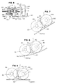
- the invention contemplates a guide mechanism, generally designated 56, for each passenger platform to guide the series of conveyor platforms between skirts 46 (Fig. 3) and maintain a minimal clearance at gaps 48 between the passenger platforms and the skirts.
- guide mechanism 56 includes a monotrack guide rail 58, and a pair of horizontal pinch rollers 60 and 62.
- the pinch rollers are rotatable about vertical axes defined by stub shafts 64 clamped to axle 52 by externally threading the stub shafts and employing clamping nuts 66. Therefore, for purposes described hereinafter, when axle 52 rotates slightly about its axis, stub shafts 64 and pinch rollers 60 and 62 will move therewith.
- pinch rollers 60 and 62 are in pinching engagement with opposite sides of monotrack guide rail 58. Initial setting of the pinch rollers into a tight pinching engagement with the guide rail is afforded by slightly elongated slots 68 in axle 52 whereby the pinch rollers can be initially set or subsequently adjusted in the direction of double headed arrows "A".
- one pinch roller 60 is of a lower compression stiffness than the other pinch roller 62.
- This differential in compression stiffness can be provided by fabricating the pinch rollers of yieldable material, such as a rubber-type material, with pinch roller 60 having a lower Durometer rating than pinch roller 62. In other words, pinch roller 60 would be softer than pinch roller 62.
- the rollers are fabricated of steel or like material, journalled by appropriate bearing means on stub shafts 64, and are covered by a urethane material.
- the periphery of pinch roller 60 i.e., its urethane covering, is formed to have a narrower peripheral rail-engaging surface than pinch roller 62.
- the urethane cover of roller 60 is molded to define a narrow rib 60a, whereas roller 62 has a wider, flat peripheral surface 62a.
- the stub shaft 64 for roller 62 can be fixed longitudinally of axle 52, rather than being longitudinally adjustable, as shown, with stub shaft 64 and, consequently, pinch roller 60 being axially adjustable of the axle since pinch roller 60 is the softer roller.
- Figure 4 also shows a bearing 70 disposed between walking beam 50 and side wall 36.
- monotrack guide rail 58 is fabricated as a unitary portion of support rail 40.
- the support rail is generally U-shaped and includes a horizontal portion 72 on which support rollers 44, as well as support roller 20 (Fig. 2) are supported.
- Monotrack guide rail 58 is formed by one leg of the U-shaped support rail.
- walking beam 50 is fixed to axle 52 and, as described above, stub shafts 54 also are fixed to the axle. Consequently, all of the these components can move or "tilt” in unison as support rollers 44 move along different portions 72 of support track 40, the support rollers being journalled to the end of axle 52.
- Figures 5-7 show how the walking beam arrangement, operatively associated between support rollers 44 and pinch rollers 60 and 62, are functional in moving between a level portion (Fig. 5) of the support track, through a transition portion (Fig. 6) of the support track, to an inclined portion (Fig. 7) of the support track.
- a level portion Fig. 5
- a transition portion Fig. 6
- Fig. 7 Fig. 7
- Fig. 1 there is an initial level portion of the escalator adjacent landing 24 (Fig. 1) which leads to the inclined area of the escalator comprising the majority of the length thereof, and ending in another level area at the top of the escalator near landing 26.
- the walking beam arrangement is provided to afford a smoother transition in these areas as well as to smooth out the "ride" should there be any irregularities in the support track system of the escalator. This is particularly advantageous for escalators because passengers are prone to stand on the very edge of the passenger platforms or steps where any non-uniform or abrupt movement of the steps is magnified into an imbalance for a passenger. Mechanically, the walking beam arrangement and the two support rollers, in essence, reduce by one-half the affect of irregularities in the track system or in the transition areas between the level and inclined portions of the escalator.
- support rollers 44 are on a level portion of support track 40, i.e., the horizontal portion 72 of the track. Consequently, walking beam 50 is level or generally horizontal since the support rollers are journalled, as at 80, to horizontally space portions of the walking beam.
- Figure 6 shows the walking beam arrangement with support rollers 44 moving through a transition portion of the support track from the level portion shown in Figure 5 to the inclined portion shown in Figure 7.
- the forward support roller 44 moves into the inclined portion of the track while the rear support roller still is on the level portion of the track.
- axle 52 is disposed equidistant between the axes of rotation of support rollers 44. Therefore, the axle will move through the transition at one-half the rate of either roller, smoothing out the "ride" of the respective passenger platform and any passenger standing thereon.
- stub shafts 64 and pinch rollers 60 and 62 will tilt with axle 52 in unison with the movement of the entire assembly through the transition area.
- Figure 7 shows the walking beam arrangement moving up the inclined portion of the support track with support rollers 44, walking beam 50, axle 52, and pinch rollers 60 and 62 resuming their relative positions as shown by the "level" or horizontal depiction of Figure 5.
Landscapes
- Escalators And Moving Walkways (AREA)
Applications Claiming Priority (2)
| Application Number | Priority Date | Filing Date | Title |
|---|---|---|---|
| US732163 | 1991-07-18 | ||
| US07/732,163 US5161668A (en) | 1991-07-18 | 1991-07-18 | Guide mechanism for passenger conveyors |
Publications (1)
| Publication Number | Publication Date |
|---|---|
| EP0523827A1 true EP0523827A1 (en) | 1993-01-20 |
Family
ID=24942435
Family Applications (1)
| Application Number | Title | Priority Date | Filing Date |
|---|---|---|---|
| EP92303822A Withdrawn EP0523827A1 (en) | 1991-07-18 | 1992-04-28 | Guide mechanism for passenger conveyors |
Country Status (8)
| Country | Link |
|---|---|
| US (1) | US5161668A (ref) |
| EP (1) | EP0523827A1 (ref) |
| JP (1) | JPH06171877A (ref) |
| KR (1) | KR100214868B1 (ref) |
| BR (1) | BR9201879A (ref) |
| CA (1) | CA2066954A1 (ref) |
| FI (1) | FI923277L (ref) |
| TW (1) | TW201722B (ref) |
Cited By (1)
| Publication number | Priority date | Publication date | Assignee | Title |
|---|---|---|---|---|
| WO2000048886A1 (fr) | 1999-02-19 | 2000-08-24 | Poma Otis Systemes De Transport | Installation de transport de personnes, en particulier a mobilite reduite, et mise en place de cette installation a partir notamment d'un escalier mecanique |
Families Citing this family (11)
| Publication number | Priority date | Publication date | Assignee | Title |
|---|---|---|---|---|
| US5522322A (en) * | 1992-03-31 | 1996-06-04 | Robert C. Warren | Motorized system and method for aiding physically-impaired persons in moving between different positions |
| KR100186368B1 (ko) * | 1996-10-22 | 1999-04-15 | 이종수 | 에스컬레이터의 터미널레일 구조 |
| US6477964B1 (en) * | 1999-10-15 | 2002-11-12 | Tygard Machine And Manufacturing Company | Guide system for a forklift |
| DE50114458D1 (de) * | 2000-03-27 | 2008-12-18 | Inventio Ag | Führungseinrichtung für Fahrtreppenstufe oder Fahrsteigpalette |
| JP4688276B2 (ja) * | 2000-11-09 | 2011-05-25 | 東芝エレベータ株式会社 | 乗客コンベア装置 |
| KR100522064B1 (ko) * | 2003-11-29 | 2005-10-18 | 오티스 엘리베이터 컴파니 | 에스컬레이터의 스텝롤러 상승억제장치 |
| KR100567285B1 (ko) * | 2004-01-16 | 2006-04-04 | 오티스 엘리베이터 컴파니 | 승객수송장치의 곡선부 핸드레일 가이드장치 |
| ZA200701671B (en) * | 2006-03-03 | 2008-08-27 | Inventio Ag | Escalator with emergency guide means |
| DE102011108093B4 (de) * | 2011-07-19 | 2020-03-05 | Siemag Tecberg Gmbh | Fertigteilfahrbahn für Schrägförderanlage für Bergbautrucks |
| JP5973720B2 (ja) * | 2011-12-26 | 2016-08-23 | 株式会社日立製作所 | 乗客コンベア |
| EP3511284B1 (en) | 2018-01-10 | 2021-09-15 | Otis Elevator Company | Moving walkway |
Citations (3)
| Publication number | Priority date | Publication date | Assignee | Title |
|---|---|---|---|---|
| AT194317B (de) * | 1955-08-05 | 1958-01-10 | Wertheim Werke Ag | Einrichtung zur Führung der Stufen bei Fahrtreppen |
| GB1171329A (en) * | 1967-08-25 | 1969-11-19 | Hitachi Ltd | Escalators |
| EP0141519A1 (en) * | 1983-09-19 | 1985-05-15 | Mitsubishi Denki Kabushiki Kaisha | A moving staircase with a curved conveyor passage |
Family Cites Families (3)
| Publication number | Priority date | Publication date | Assignee | Title |
|---|---|---|---|---|
| US927685A (en) * | 1908-12-07 | 1909-07-13 | Charles D Seeberger | Conveyer. |
| US3682289A (en) * | 1970-11-23 | 1972-08-08 | Westinghouse Electric Corp | Apparatus for guiding a conveyor |
| US4895239A (en) * | 1989-03-27 | 1990-01-23 | Otis Elevator Company | Curved escalator with fixed center constant radius path of travel |
-
1991
- 1991-07-18 US US07/732,163 patent/US5161668A/en not_active Expired - Fee Related
-
1992
- 1992-04-21 TW TW081103114A patent/TW201722B/zh active
- 1992-04-23 CA CA002066954A patent/CA2066954A1/en not_active Abandoned
- 1992-04-28 EP EP92303822A patent/EP0523827A1/en not_active Withdrawn
- 1992-05-19 BR BR929201879A patent/BR9201879A/pt not_active IP Right Cessation
- 1992-06-15 KR KR1019920010316A patent/KR100214868B1/ko not_active Expired - Fee Related
- 1992-07-10 JP JP4206167A patent/JPH06171877A/ja not_active Withdrawn
- 1992-07-17 FI FI923277A patent/FI923277L/fi not_active Application Discontinuation
Patent Citations (3)
| Publication number | Priority date | Publication date | Assignee | Title |
|---|---|---|---|---|
| AT194317B (de) * | 1955-08-05 | 1958-01-10 | Wertheim Werke Ag | Einrichtung zur Führung der Stufen bei Fahrtreppen |
| GB1171329A (en) * | 1967-08-25 | 1969-11-19 | Hitachi Ltd | Escalators |
| EP0141519A1 (en) * | 1983-09-19 | 1985-05-15 | Mitsubishi Denki Kabushiki Kaisha | A moving staircase with a curved conveyor passage |
Cited By (1)
| Publication number | Priority date | Publication date | Assignee | Title |
|---|---|---|---|---|
| WO2000048886A1 (fr) | 1999-02-19 | 2000-08-24 | Poma Otis Systemes De Transport | Installation de transport de personnes, en particulier a mobilite reduite, et mise en place de cette installation a partir notamment d'un escalier mecanique |
Also Published As
| Publication number | Publication date |
|---|---|
| BR9201879A (pt) | 1993-03-23 |
| FI923277A0 (fi) | 1992-07-17 |
| TW201722B (ref) | 1993-03-11 |
| JPH06171877A (ja) | 1994-06-21 |
| KR930002224A (ko) | 1993-02-22 |
| CA2066954A1 (en) | 1993-01-19 |
| FI923277A7 (fi) | 1993-01-19 |
| US5161668A (en) | 1992-11-10 |
| FI923277L (fi) | 1993-01-19 |
| KR100214868B1 (ko) | 1999-08-02 |
Similar Documents
| Publication | Publication Date | Title |
|---|---|---|
| US4064986A (en) | Escalator having guide wheels and guide track with cooperative non-flat surfaces | |
| US5161668A (en) | Guide mechanism for passenger conveyors | |
| KR101387200B1 (ko) | 운반 장치용 계단 체인 또는 팰릿 체인을 구비하는 구동시스템 및 대응하는 구동 시스템을 구비하는 운반 장치 | |
| AU2002227070B8 (en) | Escalator with step flange | |
| CA1220750A (en) | Passenger conveyor | |
| AU2002227070A1 (en) | Escalator with step flange | |
| US20070029163A1 (en) | Travelator, moving ramp or escalator | |
| EP0141519B1 (en) | A moving staircase with a curved conveyor passage | |
| EP0087692B1 (en) | Escalator step | |
| US5325955A (en) | Escalator step chain support apparatus | |
| US3682289A (en) | Apparatus for guiding a conveyor | |
| US4249649A (en) | Escalator having yieldable primary and non-yieldable secondary transverse guide points on one side thereof | |
| JP4754499B2 (ja) | ニューエルの上で移動するハンドレールを支持するニューエルガイド | |
| EP1101724A2 (en) | Balustrades for an escalator | |
| JP5050535B2 (ja) | マンコンベア | |
| US5020654A (en) | Curved escalator step chain turnaround zone | |
| JP7547787B2 (ja) | 乗客コンベア | |
| JP2581854B2 (ja) | マンコンベア装置 | |
| JPH02243489A (ja) | 乗客コンベヤ装置 | |
| JP2025174395A (ja) | マンコンベヤ手摺ベルト及びマンコンベヤ | |
| JP2023059389A (ja) | 乗客コンベア | |
| HK40060722A (en) | Conveying system of an escalator | |
| JP2003095569A (ja) | 乗客コンベア | |
| CN112299217A (zh) | 乘客输送机 | |
| JPS5939680A (ja) | 曲線エスカレ−タの手摺装置 |
Legal Events
| Date | Code | Title | Description |
|---|---|---|---|
| PUAI | Public reference made under article 153(3) epc to a published international application that has entered the european phase |
Free format text: ORIGINAL CODE: 0009012 |
|
| AK | Designated contracting states |
Kind code of ref document: A1 Designated state(s): BE CH DE FR GB IT LI |
|
| 17P | Request for examination filed |
Effective date: 19930628 |
|
| 17Q | First examination report despatched |
Effective date: 19950117 |
|
| STAA | Information on the status of an ep patent application or granted ep patent |
Free format text: STATUS: THE APPLICATION IS DEEMED TO BE WITHDRAWN |
|
| 18D | Application deemed to be withdrawn |
Effective date: 19950728 |