EP0523522B1 - Strahlungsmessgerät, insbesondere zur Lumineszenzmessung - Google Patents
Strahlungsmessgerät, insbesondere zur Lumineszenzmessung Download PDFInfo
- Publication number
- EP0523522B1 EP0523522B1 EP19920111537 EP92111537A EP0523522B1 EP 0523522 B1 EP0523522 B1 EP 0523522B1 EP 19920111537 EP19920111537 EP 19920111537 EP 92111537 A EP92111537 A EP 92111537A EP 0523522 B1 EP0523522 B1 EP 0523522B1
- Authority
- EP
- European Patent Office
- Prior art keywords
- radiation
- hose
- optic bundle
- injection
- housing
- Prior art date
- Legal status (The legal status is an assumption and is not a legal conclusion. Google has not performed a legal analysis and makes no representation as to the accuracy of the status listed.)
- Expired - Lifetime
Links
- 230000005855 radiation Effects 0.000 title claims description 30
- 238000004020 luminiscence type Methods 0.000 title claims description 19
- 238000002347 injection Methods 0.000 claims description 42
- 239000007924 injection Substances 0.000 claims description 42
- 239000000835 fiber Substances 0.000 claims description 13
- 238000006243 chemical reaction Methods 0.000 claims description 8
- 239000000126 substance Substances 0.000 claims description 7
- 229910052782 aluminium Inorganic materials 0.000 claims description 3
- XAGFODPZIPBFFR-UHFFFAOYSA-N aluminium Chemical compound [Al] XAGFODPZIPBFFR-UHFFFAOYSA-N 0.000 claims description 3
- 229910052751 metal Inorganic materials 0.000 claims description 2
- 239000002184 metal Substances 0.000 claims description 2
- 239000004810 polytetrafluoroethylene Substances 0.000 claims 2
- 229920001343 polytetrafluoroethylene Polymers 0.000 claims 2
- 229910000831 Steel Inorganic materials 0.000 claims 1
- 239000004411 aluminium Substances 0.000 claims 1
- 208000015181 infectious disease Diseases 0.000 claims 1
- 230000000977 initiatory effect Effects 0.000 claims 1
- 239000010959 steel Substances 0.000 claims 1
- 238000005259 measurement Methods 0.000 description 9
- 230000003213 activating effect Effects 0.000 description 5
- 239000000243 solution Substances 0.000 description 3
- 230000015572 biosynthetic process Effects 0.000 description 2
- 230000035945 sensitivity Effects 0.000 description 2
- 238000012360 testing method Methods 0.000 description 2
- 238000010521 absorption reaction Methods 0.000 description 1
- 230000001154 acute effect Effects 0.000 description 1
- 238000004458 analytical method Methods 0.000 description 1
- 230000015556 catabolic process Effects 0.000 description 1
- 239000003153 chemical reaction reagent Substances 0.000 description 1
- 238000004140 cleaning Methods 0.000 description 1
- 238000010276 construction Methods 0.000 description 1
- 238000006731 degradation reaction Methods 0.000 description 1
- 238000013461 design Methods 0.000 description 1
- 238000011156 evaluation Methods 0.000 description 1
- 239000007788 liquid Substances 0.000 description 1
- 238000012423 maintenance Methods 0.000 description 1
- 238000000034 method Methods 0.000 description 1
- 230000003287 optical effect Effects 0.000 description 1
- 239000013307 optical fiber Substances 0.000 description 1
- 230000035515 penetration Effects 0.000 description 1
- 238000000926 separation method Methods 0.000 description 1
- 229910001220 stainless steel Inorganic materials 0.000 description 1
- 239000010935 stainless steel Substances 0.000 description 1
- 238000012549 training Methods 0.000 description 1
- 238000011144 upstream manufacturing Methods 0.000 description 1
Images

Classifications
-
- G—PHYSICS
- G01—MEASURING; TESTING
- G01N—INVESTIGATING OR ANALYSING MATERIALS BY DETERMINING THEIR CHEMICAL OR PHYSICAL PROPERTIES
- G01N21/00—Investigating or analysing materials by the use of optical means, i.e. using sub-millimetre waves, infrared, visible or ultraviolet light
- G01N21/75—Systems in which material is subjected to a chemical reaction, the progress or the result of the reaction being investigated
- G01N21/76—Chemiluminescence; Bioluminescence
-
- G—PHYSICS
- G01—MEASURING; TESTING
- G01N—INVESTIGATING OR ANALYSING MATERIALS BY DETERMINING THEIR CHEMICAL OR PHYSICAL PROPERTIES
- G01N2201/00—Features of devices classified in G01N21/00
- G01N2201/06—Illumination; Optics
- G01N2201/064—Stray light conditioning
-
- G—PHYSICS
- G01—MEASURING; TESTING
- G01N—INVESTIGATING OR ANALYSING MATERIALS BY DETERMINING THEIR CHEMICAL OR PHYSICAL PROPERTIES
- G01N2201/00—Features of devices classified in G01N21/00
- G01N2201/08—Optical fibres; light guides
- G01N2201/084—Fibres for remote transmission
-
- G—PHYSICS
- G01—MEASURING; TESTING
- G01N—INVESTIGATING OR ANALYSING MATERIALS BY DETERMINING THEIR CHEMICAL OR PHYSICAL PROPERTIES
- G01N35/00—Automatic analysis not limited to methods or materials provided for in any single one of groups G01N1/00 - G01N33/00; Handling materials therefor
- G01N35/10—Devices for transferring samples or any liquids to, in, or from, the analysis apparatus, e.g. suction devices, injection devices
Definitions
- the invention relates to a radiation measuring device, in particular for Luminescence measurement according to the preamble of patent claim 1.
- Such a radiation measuring device is known from US Pat. No. 4,772,453. Because of the luminescence reaction upwards from one In this known arrangement, the light emerging from the sample vessel via a collection and deflection optics in a light-tight housing arranged photomultiplier fed. The injection device for penetration of the substance activating the luminescence reaction is next to the next one sample vessel to be measured, so that between the addition of the injection liquid and the start of the luminescence measurement inevitably there is a dead time due to the transport of the sample vessels by one Position is further caused.
- EP-A-0 136 002 proposes for absorption measurement that Tip of one arranged laterally by a light detector Injection device in an area below the light detector turn if there is a shift in the currently measured Sample vessel between injection and measurement should be avoided.
- this has the disadvantage that a relatively large part of the Light path is blocked, which leads to a degradation of the Sensitivity.
- EP-0 181 060 A2 shows one possibility of a plurality of to be measured in a matrix-like manner and is thus basically also for the use of the mentioned micro test plates suitable; however, nothing is said there about the addition of the Luminescence reaction activating substance, which is consequently only before Attach the radiation detector or the fiber optic cable can take place and therefore the disadvantages explained above generic U.S. Patent 4,772,453 implies.
- the task is based on the generic radiation measuring device the invention therefore in further developing this device that measurement and injection can take place simultaneously, whereby especially the possibility of measuring micro test plates should be preserved.
- a bundle is advantageously used as the elements for light guidance used by about 8-9 light guides / the formation of the end area the injection device as an injection hose or tube, the then at an acute angle into a gap between these neighboring ones Light guides is led below the entrance panel, ensures that, on the one hand, the concentric arrangement of the The light guide in the light guide bundle is not disturbed and on the other hand the inevitable loss of sensitivity caused by the in tip of the injection tube protruding through the inlet cross-section can be minimized.
- the injection hose outside the light guide bundle is guided in a housing where it has an upper flange stuck on the bottom of a bore of the housing and being Flange is coupled to the flange of a connecting hose, for what the bore of the housing has at least partially an internal thread, in which a threaded fitting is passed through which the connecting hose extends axially such that the flanges of injection hose and connecting hose when the threaded fitting is tightened are pressed tightly against each other.
- This structure enables easy assembly / disassembly of the Elements of the injection device, especially for cleaning purposes is very useful.
- the radiation measuring device consists essentially of three components: a bundle 30 of light guides, one of which End is assigned to a sample vessel B, from which the to be measured Radiation S occurs, and its other end to one Radiation detector 40, for example a photomultiplier is coupled, which measures this radiation, as well as with one above of the sample vessel B arranged housing 20 for receiving different injection devices 10 and 50.
- the geometry of the arrangement shown in the exemplary embodiment is chosen such that the inlet cross section 21 of the light guide bundle 30 lies horizontally and the light guide bundle 30 around one Angle of 90 ° is deflected into the horizontal, so that the Longitudinal axis of the subsequent photomultiplier 40 lies horizontally.
- the light guide bundle 30 consists of eight or nine in parallel extending light guides 31, for example so that around a central light guide grouped eight additional light guides in a circle are.
- the light guide bundle 30 is at its front end of enclosed a metal sleeve 33, which is made in particular of stainless steel is manufactured and, so to speak, the lateral, optical conclusion of the Optical fiber bundle 30 forms.
- an aluminum tube 32 serves as the photomultiplier facing end 32A a union nut 34 is arranged by the tube 32 rotatable and detachable with the entrance of the Radiation detector 40 is connectable.
- the other end 32A of the tube 32 sits in an aluminum housing 20, which extends to the inlet cross section 21 and in essential for accommodating the injection devices 10 and 50 serves.
- the two injection devices 10 and 50 are structurally the same built up, so that in the following the reference numerals reproduce corresponding components, in brackets for the second Injection device 50 are shown:
- Bores of different diameters and different are in the housing 20 Type introduced, which is cone-shaped from the upper Extend surface substantially vertically downwards the longitudinal axis of the bore of the first injection device 10 around an angle ⁇ of about 20 ° to the vertical is inclined corresponding bore for the second injection device 50 runs vertically or at a very small angle of about 3-5 ° inclined from the vertical.
- the lower part of the hole is dimensioned so that it is one Injection hose 11 (51) takes so long that his lower tip emerges from the housing 20, which is important is that the tip of the injection hose 11 in the inlet cross section 21 ends, the tip of the injection hose 51 outside from that.
- the injection hose 11 has one inserted flange 11A (51A), with which he on the by a Widening of the bore 22 formed ring shoulder 22A is seated.
- the flange 12A closes directly on the flange 11A (52A) of a connecting hose 12 (52).
- the connecting hose 12 runs through a threaded fitting 13, the lower one, in the bore 22 seated end 13A has a thread with which it is in one corresponding internal thread 22B of the bore 22 are tightened can.
- the upper end 13B (32B) is in the illustrated embodiment designed as a polygonal screw.
- the injection device 10 in FIG. 1 (left side) explained components shown in an exploded view are on the right side with respect to the injection device 50 1 shown in the assembled state: This is the threaded fitting 13 screwed into the bore 22 when tightened Thread fitting are the two facing surfaces of the Flanges 11A / 12A (51A / 52A) pressed tightly together. Not that one shown) other end of the connecting hoses 12 (52) is for example each connected to a pump through which a chemical Substance through the injection tube 11 (51) into a sample container B can be injected, which is either immediately below the Inlet orifice 21 (injection hose 11) or right next to it (Injection hose 51).
- the corresponding chemical reagent for example a luminescence activating Substance
- the corresponding chemical reagent for example a luminescence activating Substance
- the radiation measuring device is simple in construction, the injection devices 10 (50) can, especially from the exploded view 1 is easily seen, simply disassembled and cleaned if necessary, the tube 32 can be by means of the union nut 34 easily detached from the detector 40 and around the longitudinal axis of the Photomultipliers are pivoted so that the plane of the entrance cross section 21 is pivotable out of the horizontal and in the field of vision of the user can be pivoted.
- the detachability of the entire assembly 32/20 from the detector 40 also very easily possible, for repair or maintenance work Replacement module to connect to the radiation detector 40 and the Continue measurement immediately afterwards.
Landscapes
- Physics & Mathematics (AREA)
- Chemical & Material Sciences (AREA)
- Biochemistry (AREA)
- General Health & Medical Sciences (AREA)
- Plasma & Fusion (AREA)
- Health & Medical Sciences (AREA)
- Life Sciences & Earth Sciences (AREA)
- Analytical Chemistry (AREA)
- Engineering & Computer Science (AREA)
- Chemical Kinetics & Catalysis (AREA)
- General Physics & Mathematics (AREA)
- Immunology (AREA)
- Pathology (AREA)
- Investigating Or Analysing Materials By The Use Of Chemical Reactions (AREA)
- Investigating, Analyzing Materials By Fluorescence Or Luminescence (AREA)
- Measurement Of Radiation (AREA)
Description
- Fig. 1
- einen Vertikalschnitt durch ein Ausführungsbeispiel der ersten Lösungsvariante des Strahlungsmeßgerätes in der Ebene I-I der Fig. 3,
- Fig. 2
- eine Unteransicht in Richtung des Pfeiles P der Fig.1,
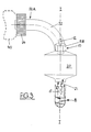
- Fig. 3
- eine Seitenansicht in Richtung des Pfeiles A der Fig. 1.
Claims (9)
- Strahlungsmeßgerät, insbesondere, zur Lumineszenzmessung, mit einem Strahlungsdetektor, insbesondere einem Photomultiplier, der oberhalb eines Probengefäßes angeordnet werden kann, um die aus einer Öffnung des Probengefäßes austretende Strahlung zu erfassen, sowie mit einer Injektionsvorrichtung zur Zugabe einer chemischen Substanz in diese Öffnung des Probengefäßes, insbesondere zur Initiierung der Lumineszenzreaktion,
dadurch gekennzeichnet,
daß ein Lichtleiterbündel (30) mit einer Eintrittsblende vorgesehen ist, daß das Bündel die aus besagter Öffnung des Probengefäßes austretende, in die Eintrittsblende einfallende, Strahlung zum Strahlungsdetektor (40) leitet, und daß der Endbereich der Injektionsvorrichtung (10) als Injektionsschlauch oder -rohr (11) ausgebildet ist, der/das unter spitzem Winkel (α) relativ zu den Lichtleitern (31) in eine Lücke zwischen benachbarten Lichtleitern (31) innerhalb des Lichtleiterbündels (30) geführt ist, so daß das Ende des Injektionsschlauchs bzw.-rohres im Eintritts querschnitt des Lichtleiterbündels unterhalb der Eintrittsblende endet. - Strahlungsmeßgerät nach Anspruch 1, dadurch gekennzeichnet, daß das Lichtleiterbündel (30) aus 5-10, insbesondere 8 oder 9 Lichtleitern (31) besteht.
- Strahlungsmeßgerät nach Anspruch 1, dadurch gekennzeichnet, daß das Ende des Injektionsschlauchs bzw.-Rohres durch den Umfangs- oder Randbereich des Lichtleiterbündels (30) geführt ist.
- Strahlungsmeßgerät nach Anspruch 1, dadurch gekennzeichnet, daß der Injektionsschlauch (11) außerhalb des Lichtleiterbündels (30) in einem Gehäuse (20) geführt ist, wo er mit einem oberen Flansch (11A) auf einer Ringschulter (22A) einer Bohrung (22) des Gehäuses (20) festsitzt.
- Strahlungsmeßgerät nach Anspruch 4, dadurch gekennzeichnet, daß der Flansch (11A) des Injektionsschlauches (11) mit dem Flansch (12A) eines Anschlußschlauchs (12) gekoppelt ist, wozu die Bohrung (22) des Gehäuses (20) zumindest teilweise ein Innengewinde (22B) aufweist, in dem ein Gewindefitting (13) geführt ist, durch den sich der Anschlußschlauch (12) axial erstreckt, derart, daß die Flansche (11A,12A) von Injektionsschlauch (11) und Anschlußschlauch (12) bei festgezogenem Gewindefitting (13) dichtend aufeinandergepreßt sind.
- Strahlungsmeßgerät nach Anspruch 5, dadurch gekennzeichnet, daß das aus der Bohrung (22) des Gehäuses (20) ragende Ende des Gewindefitting (13) als Mehrkant- oder Rändelschraube (13B) ausgeführt ist.
- Strahlungsmeßgerät nach Anspruch 5, dadurch gekennzeichnet, daß Injektionsschlauch (11) und Anschlußschlauch (12) aus PTFE, insbesondere schwarz pigmentiertem PTFE, sind.
- Strahlungsmeßgerät nach Anspruch 1 und 4, dadurch gekennzeichnet, daß das Lichtleiterbündel (30) in einem Rohr (32), vorzugsweise aus Aluminium, geführt ist, dessen eines Ende (32A) vom Gehäuse (20) umschlossen ist und dessen anderes Ende mittels einer Überwurfmutter (34) dreh- und lösbar mit dem Strahlungsdetektor (40) verbunden ist, daß das Lichtleiterbündel (30) mit Hilfe des knieförmig abgebogenen Rohrs (32) um 90° aus seinem vertikalen Verlauf innerhalb des Gehäuses (20) zu dem horizontal liegenden Strahlungsdetektor (40) umgelenkt wird, und daß zwischen Lichtleiterbündel (30) und Rohr (32) eine Metallhülse (33), vorzugsweise aus Edelstahl, angeordnet ist, die sich über den Anschlußbereich zu den Probengefäßen erstreckt.
- Strahlungsmeßgerät nach Anspruch 1 und 4, dadurch gekennzeichnet, daß das Gehäuse (20) eine weitere Injektionsvorrichtung (50) aufnimmt, die außerhalb des Eintrittsquerschnitts der Eintrittsblende (21) endet, und die vorzugsweise ebenfalls aus Injektionsschlauch (51), Anschlußschlauch (52) mit zugehörigen Flanschen (51A,52A) und Gewindefitting (53) besteht.
Priority Applications (1)
| Application Number | Priority Date | Filing Date | Title |
|---|---|---|---|
| EP97111105A EP0795745B1 (de) | 1991-07-18 | 1992-07-08 | Strahlungsmessgerät insbesondere zur Lumineszenzmessung |
Applications Claiming Priority (2)
| Application Number | Priority Date | Filing Date | Title |
|---|---|---|---|
| DE4123818 | 1991-07-18 | ||
| DE19914123818 DE4123818C2 (de) | 1991-07-18 | 1991-07-18 | Vorrichtung zur Messung der Chemilumineszenz einer in einem Probengefäß befindlichen Probe |
Related Child Applications (1)
| Application Number | Title | Priority Date | Filing Date |
|---|---|---|---|
| EP97111105A Division EP0795745B1 (de) | 1991-07-18 | 1992-07-08 | Strahlungsmessgerät insbesondere zur Lumineszenzmessung |
Publications (3)
| Publication Number | Publication Date |
|---|---|
| EP0523522A2 EP0523522A2 (de) | 1993-01-20 |
| EP0523522A3 EP0523522A3 (en) | 1994-09-14 |
| EP0523522B1 true EP0523522B1 (de) | 1998-12-09 |
Family
ID=6436455
Family Applications (2)
| Application Number | Title | Priority Date | Filing Date |
|---|---|---|---|
| EP97111105A Expired - Lifetime EP0795745B1 (de) | 1991-07-18 | 1992-07-08 | Strahlungsmessgerät insbesondere zur Lumineszenzmessung |
| EP19920111537 Expired - Lifetime EP0523522B1 (de) | 1991-07-18 | 1992-07-08 | Strahlungsmessgerät, insbesondere zur Lumineszenzmessung |
Family Applications Before (1)
| Application Number | Title | Priority Date | Filing Date |
|---|---|---|---|
| EP97111105A Expired - Lifetime EP0795745B1 (de) | 1991-07-18 | 1992-07-08 | Strahlungsmessgerät insbesondere zur Lumineszenzmessung |
Country Status (3)
| Country | Link |
|---|---|
| EP (2) | EP0795745B1 (de) |
| JP (1) | JP2553437B2 (de) |
| DE (1) | DE4123818C2 (de) |
Families Citing this family (11)
| Publication number | Priority date | Publication date | Assignee | Title |
|---|---|---|---|---|
| DE4306184A1 (de) * | 1993-02-27 | 1994-09-01 | Joerg Doerpinghaus | Vorrichtung zum kontinuierlichen Erfassen physikalischer und/oder chemischer Parameter von Flüssigkeiten |
| DE4332165A1 (de) * | 1993-09-22 | 1995-03-23 | Kolibri Umweltanalytik Und On | Verfahren und Gerät zur Schadstoffanalyse von Gewässerproben |
| DE19704731B4 (de) * | 1997-02-07 | 2006-07-27 | Stratec Biomedical Systems Ag | Meßgerät zur Durchführung von Lumineszenzmessungen |
| WO1999009394A1 (en) * | 1997-08-15 | 1999-02-25 | Alexion Pharmaceuticals, Inc. | Apparatus for performing assays at reaction sites |
| AU2002306207B2 (en) * | 1997-08-15 | 2005-02-24 | Bioprocessors, Corp. | Apparatus for performing assays at reaction sites |
| DE19755187C2 (de) * | 1997-12-11 | 2001-04-26 | Berthold Detection Systems Gmb | Vorrichtung zur Messung der Lumineszenz oder Fluoreszenz einer Probe |
| ES2151857B1 (es) * | 1999-03-23 | 2001-07-16 | Univ Madrid Autonoma | Equipo para la deteccion de alimentos que han sido expuestos a radiacion ionizante para su esterilizacion. |
| DE10136866A1 (de) * | 2001-07-28 | 2003-02-20 | Berthold Tech Gmbh & Co Kg | Strahlungsmessgerät, insbesondere zur Messung der Lumineszenz |
| DE10136865B4 (de) * | 2001-07-28 | 2007-11-15 | Berthold Technologies Gmbh & Co. Kg | Vorrichtung zur Messung der Chemilumineszenz |
| DE102005025848B3 (de) * | 2005-06-06 | 2007-02-15 | Protagon Process Technologies Gmbh | Optische Messvorrichtung und Verwendung der Messvorrichtung zur Messung von Beschichtungen auf organischer- und/oder Polymer-Basis |
| JP5479967B2 (ja) * | 2010-03-25 | 2014-04-23 | 国立大学法人名古屋大学 | 高感度発光測定装置 |
Family Cites Families (12)
| Publication number | Priority date | Publication date | Assignee | Title |
|---|---|---|---|---|
| US3997404A (en) * | 1974-06-07 | 1976-12-14 | Johnston Laboratories, Inc. | Method and apparatus for characterizing biologically active agents |
| DE2901919C2 (de) * | 1979-01-18 | 1987-04-02 | Laboratorium Prof. Dr. Rudolf Berthold, 7547 Wildbad | Verfahren zur photometrischen Reihenmessung an Reaktionsvorgängen in flüssigen Proben und Vorrichtung zur Durchführung des Verfahrens |
| JPS55155235A (en) * | 1979-05-22 | 1980-12-03 | Aloka Co Ltd | Analysis for trace component in test piece |
| US4297105A (en) * | 1980-06-27 | 1981-10-27 | Alcan Research And Development Limited | Automatic photometric titrator |
| DE3110239A1 (de) * | 1981-03-17 | 1982-10-07 | Seppo 32780 Titusville Fla. Kolehmainen | Verfahren und vorrichtung zum messen der lumineszenz von proben |
| FI833077A0 (fi) * | 1983-08-30 | 1983-08-30 | Labsystems Oy | Med en vaetskedoserare foersedd maetningsanordning |
| FI843538A0 (fi) * | 1984-09-10 | 1984-09-10 | Labsystems Oy | Foerfarande och vid detta anvaend apparatur foer maetning av straolning. |
| JPS6199843A (ja) * | 1984-10-22 | 1986-05-17 | Meidensha Electric Mfg Co Ltd | 分注方法 |
| US4772453A (en) * | 1985-03-01 | 1988-09-20 | Lisenbee Wayne F | Luminiscence measurement arrangement |
| DE3623601C2 (de) * | 1986-07-12 | 1997-01-16 | Berthold Lab Prof Dr | Meßgerät für Bio- und Chemilumineszenz |
| GB2211607A (en) * | 1987-10-29 | 1989-07-05 | Cardiff Energy & Resources | Injection systems for luminometers |
| US5089424A (en) * | 1988-06-14 | 1992-02-18 | Abbott Laboratories | Method and apparatus for heterogeneous chemiluminescence assay |
-
1991
- 1991-07-18 DE DE19914123818 patent/DE4123818C2/de not_active Expired - Fee Related
-
1992
- 1992-07-08 EP EP97111105A patent/EP0795745B1/de not_active Expired - Lifetime
- 1992-07-08 EP EP19920111537 patent/EP0523522B1/de not_active Expired - Lifetime
- 1992-07-20 JP JP4214551A patent/JP2553437B2/ja not_active Expired - Fee Related
Also Published As
| Publication number | Publication date |
|---|---|
| EP0795745A3 (de) | 1998-04-15 |
| JP2553437B2 (ja) | 1996-11-13 |
| JPH05209831A (ja) | 1993-08-20 |
| DE4123818C2 (de) | 1994-05-19 |
| EP0523522A2 (de) | 1993-01-20 |
| DE4123818A1 (de) | 1993-01-21 |
| EP0523522A3 (en) | 1994-09-14 |
| EP0795745A2 (de) | 1997-09-17 |
| EP0795745B1 (de) | 2003-06-25 |
Similar Documents
| Publication | Publication Date | Title |
|---|---|---|
| DE69112334T2 (de) | Luftdetektor für dünnwandige Schläuche. | |
| DE3446756C1 (de) | Photometer zum Analysieren fluessiger Medien | |
| DE523680T1 (de) | Photometrisches Gerät. | |
| DE4123818C2 (de) | Vorrichtung zur Messung der Chemilumineszenz einer in einem Probengefäß befindlichen Probe | |
| DE3344387A1 (de) | Photometerkopf fuer kleine messvolumina | |
| DE202005011177U1 (de) | Vorrichtung zur Analyse, insbesondere fotometrischen oder spektralfotometrischen Analyse | |
| CH618266A5 (en) | Spectrophotometer. | |
| DE2260561C3 (de) | DurchfluBküvette zur fotometrischen Analyse von Fluidproben | |
| DE2904909C3 (de) | Küvette für optische Messungen | |
| DE2636470C2 (de) | Fotoanalysegerät zur gleichzeitigen optischen Messung einer Anzahl von Eigenschaften eines in einer Suspension enthaltenen Systems kleiner Teilchen | |
| DE69705937T2 (de) | Optisches gerät | |
| EP0660106B1 (de) | Vorrichtung mit einem Spektralphotometer und Lichtleitern | |
| DE19649264A1 (de) | Flammenbeobachtungsgerät | |
| DE19727484A1 (de) | Verfahren und Vorrichtung zum Vermessen eines aus einer Sprühdüse austretenden Sprühstrahls | |
| DE3315456C2 (de) | Vorrichtung zur Bestimmung von Partikelgrößen | |
| DE4014374A1 (de) | Proben-aufnehmer oder proben-analysator zur optischen analyse einer probe | |
| EP0294367A1 (de) | Einrichtung zum erfassen der radialen intensitätsverteilung einer laserstrahlung. | |
| EP1910807B1 (de) | Vorrichtung für die analyse oder absorptionsmessung an einer kleinen flüssigkeitsmenge | |
| DE19704731A1 (de) | Meßgerät zur Durchführung von Lumineszenzmessungen | |
| DE3428364C2 (de) | ||
| DE4427314C2 (de) | Vorrichtung zur Untersuchung von Behältern auf Fremdgase | |
| DE10001895A1 (de) | Analysenvorrichtung und Antriebsvorrichtung hierfür | |
| DE20103881U1 (de) | Vorrichtung zum Messen von ionisierender Strahlung | |
| DE19506675A1 (de) | Vorrichtung zur Einkopplung von durch eine Probe transmittiertem oder von einer Probe reflektiertem, gestreutem, emittiertem oder reemittiertem Licht in einen Lichtleiter | |
| DE2751738A1 (de) | Vorrichtung zum messtechnischen erfassen von in einer fluessigkeit enthaltenen stoffen |
Legal Events
| Date | Code | Title | Description |
|---|---|---|---|
| PUAI | Public reference made under article 153(3) epc to a published international application that has entered the european phase |
Free format text: ORIGINAL CODE: 0009012 |
|
| AK | Designated contracting states |
Kind code of ref document: A2 Designated state(s): FR GB |
|
| PUAL | Search report despatched |
Free format text: ORIGINAL CODE: 0009013 |
|
| AK | Designated contracting states |
Kind code of ref document: A3 Designated state(s): FR GB |
|
| 17P | Request for examination filed |
Effective date: 19941013 |
|
| 17Q | First examination report despatched |
Effective date: 19961105 |
|
| GRAG | Despatch of communication of intention to grant |
Free format text: ORIGINAL CODE: EPIDOS AGRA |
|
| GRAG | Despatch of communication of intention to grant |
Free format text: ORIGINAL CODE: EPIDOS AGRA |
|
| GRAH | Despatch of communication of intention to grant a patent |
Free format text: ORIGINAL CODE: EPIDOS IGRA |
|
| GRAH | Despatch of communication of intention to grant a patent |
Free format text: ORIGINAL CODE: EPIDOS IGRA |
|
| GRAA | (expected) grant |
Free format text: ORIGINAL CODE: 0009210 |
|
| AK | Designated contracting states |
Kind code of ref document: B1 Designated state(s): FR GB |
|
| DX | Miscellaneous (deleted) | ||
| GBT | Gb: translation of ep patent filed (gb section 77(6)(a)/1977) |
Effective date: 19981210 |
|
| ET | Fr: translation filed | ||
| PLBE | No opposition filed within time limit |
Free format text: ORIGINAL CODE: 0009261 |
|
| STAA | Information on the status of an ep patent application or granted ep patent |
Free format text: STATUS: NO OPPOSITION FILED WITHIN TIME LIMIT |
|
| 26N | No opposition filed | ||
| REG | Reference to a national code |
Ref country code: GB Ref legal event code: IF02 |
|
| REG | Reference to a national code |
Ref country code: FR Ref legal event code: TP |
|
| PGFP | Annual fee paid to national office [announced via postgrant information from national office to epo] |
Ref country code: FR Payment date: 20090720 Year of fee payment: 18 |
|
| PGFP | Annual fee paid to national office [announced via postgrant information from national office to epo] |
Ref country code: GB Payment date: 20090724 Year of fee payment: 18 |
|
| GBPC | Gb: european patent ceased through non-payment of renewal fee |
Effective date: 20100708 |
|
| REG | Reference to a national code |
Ref country code: FR Ref legal event code: ST Effective date: 20110331 |
|
| PG25 | Lapsed in a contracting state [announced via postgrant information from national office to epo] |
Ref country code: FR Free format text: LAPSE BECAUSE OF NON-PAYMENT OF DUE FEES Effective date: 20100802 |
|
| PG25 | Lapsed in a contracting state [announced via postgrant information from national office to epo] |
Ref country code: GB Free format text: LAPSE BECAUSE OF NON-PAYMENT OF DUE FEES Effective date: 20100708 |