EP0521816B1 - Method for transferring a yarn from a full bobbin to a winding tube and winding machine - Google Patents
Method for transferring a yarn from a full bobbin to a winding tube and winding machine Download PDFInfo
- Publication number
- EP0521816B1 EP0521816B1 EP92810369A EP92810369A EP0521816B1 EP 0521816 B1 EP0521816 B1 EP 0521816B1 EP 92810369 A EP92810369 A EP 92810369A EP 92810369 A EP92810369 A EP 92810369A EP 0521816 B1 EP0521816 B1 EP 0521816B1
- Authority
- EP
- European Patent Office
- Prior art keywords
- yarn
- thread
- full bobbin
- hook
- winding
- Prior art date
- Legal status (The legal status is an assumption and is not a legal conclusion. Google has not performed a legal analysis and makes no representation as to the accuracy of the status listed.)
- Expired - Lifetime
Links
Images


Classifications
-
- B—PERFORMING OPERATIONS; TRANSPORTING
- B65—CONVEYING; PACKING; STORING; HANDLING THIN OR FILAMENTARY MATERIAL
- B65H—HANDLING THIN OR FILAMENTARY MATERIAL, e.g. SHEETS, WEBS, CABLES
- B65H67/00—Replacing or removing cores, receptacles, or completed packages at paying-out, winding, or depositing stations
- B65H67/04—Arrangements for removing completed take-up packages and or replacing by cores, formers, or empty receptacles at winding or depositing stations; Transferring material between adjacent full and empty take-up elements
- B65H67/044—Continuous winding apparatus for winding on two or more winding heads in succession
- B65H67/048—Continuous winding apparatus for winding on two or more winding heads in succession having winding heads arranged on rotary capstan head
-
- B—PERFORMING OPERATIONS; TRANSPORTING
- B65—CONVEYING; PACKING; STORING; HANDLING THIN OR FILAMENTARY MATERIAL
- B65H—HANDLING THIN OR FILAMENTARY MATERIAL, e.g. SHEETS, WEBS, CABLES
- B65H2701/00—Handled material; Storage means
- B65H2701/30—Handled filamentary material
- B65H2701/31—Textiles threads or artificial strands of filaments
Definitions
- the present invention relates to a method for transferring the thread from a full bobbin to an empty tube according to the preamble of claim 1.
- the invention further relates to a winder according to the preamble of patent claim 5.
- the incoming threads When winding threads on winding machines with a turret carrying the winding mandrels, the incoming threads must be transferred from the full bobbin to an empty tube, which has been brought into the winding position by rotating the turret, after the winding process has ended.
- the transfer should take place waste-free and with the formation of an end bead consisting of an accumulation of threads on the full bobbin and a thread bead outside the traversing area on the sleeve of the new bobbin.
- the first type of such devices moves the sleeve or the coil mandrel with the sleeve axially during the coil change, so that the beads are produced at the desired locations.
- These devices have the disadvantage that the spool mandrels rotating at high speed must be designed to be displaceable on the turret, which requires a high mechanical outlay when the spool mandrels are mounted on the turret.
- a winding device in which the thread coming from the thread traversing, leading thread is deflected into the plane of the thread slot on the empty tube by a first thread guide in the form of a disengaging element acting on the thread running onto the spool.
- the thread running to the full bobbin is deflected by means of a second element acting on the thread, which is located behind the first thread guide in the running direction of the thread and on which the turret carrying the bobbin pins is fastened.
- a third thread guide deflects the thread axially from the run-up point onto the second thread guide in such a way that the incoming thread comes to lie in the plane of the catch slot of the empty tube.
- This known device has the disadvantage that the second thread guide, which is firmly connected to the turret and is consequently rotatable in synchronism with the spools, deflects the thread still running to the full spool by more than 90 ° in a first plane running perpendicular to the spools and after the third thread guide engages, the thread is additionally deflected by an angle of more than 45 °.
- Such strong deflections in the case of threads fed to the bobbin at high speed can lead to thread damage or even thread breaks.
- the deflection of the thread by the second thread guide lasts for a very long time, starting shortly after the full bobbin is swung away from the distribution roller until and at the time the thread is transferred to the catch slot of the new tube. Damage to the thread can consequently take place over a very long period, so that larger quantities are affected.
- the object of the present invention is to provide a method for transferring the thread from a full to an empty tube, in which the thread running to the full, in the change position bobbin is deflected only for a very short time and the deflection of the thread only briefly experiences a further deflection during the transfer of the thread to the thread slot.
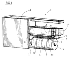
- FIG. 1 a winding machine 1 with two winding mandrels 5, 7 mounted on a rotatable turret 2, a thread laying device 6 is known Construction and the machine housing 9 shown, which contains the drive motors for the contact rollers 8, the laying device 6 and the other units and parts of the controller.
- the turret 2, which carries the two mandrels 5, 7, has a known design and is rotatably mounted about the axis A.
- the two spools 5, 7 are overhung on the turret 2, which means that the empty tube 11 can be loaded or the full spools 3 can be removed by hand or by an automatic doffer on the front.
- a thread deflecting rod 13 is visible, which is pivotably attached to the machine housing 9 on a crank 15 mounted on an axis B.
- the end of an exchangeable plate 17, which will be described in more detail later, is visible behind the spool mandrel 7.
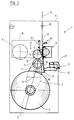
- the contact roller 8 and the traversing device 6 are vertically movably mounted on the machine housing 9 on a common carrier slide 10, so that the contact roller 8 can move upwards with increasing diameter of the coil 3 while maintaining a constant contact pressure.
- the regulation of the contact pressure and the device for displacing the carrier 10 are known from the prior art and are not the subject of this invention. They are therefore not described in more detail.
- the dash-dotted thread 14 runs from above to the machine and is changed by a thread guide 12 on the traversing device 6 in a known manner across the width of the bobbin 3 to be produced. Above the traversing device 6, a thread lifting device 19 for lifting the thread 14 out of the thread guide of the traversing device 6 is visible.
- the thread lifting device 19 can consist of a thread lifting plate 21 which can be pivoted about an axis C.
- a guide plate 25 which can be pivoted about the axis C in the thread run is intended to axially guide the thread 3 lifted from the traversing 6 into a plane Z running through the thread catching slot 23 on the sleeve 11 (see FIGS. 3B-10B).
- an interchangeable plate 17 is arranged on a bracket 27 which can be pivoted about an axis G and can be pivoted from a rest position (FIG. 3A) via a take-over position (7A) into a transfer position (9A).
- a rest position FIG. 3A
- a take-over position 7A
- a transfer position 9A
- FIGS. 3A and 3B show the winding machine 1 at the time of the start of a bobbin change.
- the full bobbin 3 is lifted off the contact roller 8 by turning the turret 2 clockwise.
- the incoming thread 14, which is guided through an eyelet 29, is further changed by the thread guide 12 on the traversing device 6 over the entire stroke h1 of the still rotating bobbin 3 (FIG. 3B).
- the deflecting rod 13 is pivoted into the thread path of the thread 14 from the left side, visible in FIG.
- FIG. 5A it can be seen that when the revolver 2 with the full bobbin 3 and the empty sleeve 5 is pivoted further, the carrier slide 10 has lowered and as a result the free thread length between the oscillation 6 and the bobbin 3 with respect to the conditions in FIGS.
- the thread 14 is now guided axially laterally out of the traversing area (stroke) in order to reach plane Z (guide plate 25) on the one hand and plane X (hook 31) on the other hand.
- the deflecting rod 13 can pivot back and release the thread transfer.
- the fixed hook 31 and a pivotable hook 33 are attached to the interchangeable plate 17 (FIG. 11).
- the fixed hook 31 determines the axial position for the end bead 37 on the surface of the full coil 3 (dash-dotted line X).
- the hook 33 which can be swiveled back about the axis 41 behind the front edge 39 of the interchangeable plate 17 lies in the swiveled-back position within the interchangeable plate 17.
- the interchangeable plate 17 pivots further, advances the thread 14 and causes the empty sleeve 11 to be looped through the thread 14 (FIGS. 8A and 8B).
- the thread 14 reaches the area of the thread catching slot 23, it is grasped by the latter and the section of the thread 14 running to the full bobbin 3 is torn in two.
- the lifting plate 21 swings back into the starting position, so that the thread 14 from the thread guide 12 in the Traversing device 6 detected and the construction of a new coil 3 can be started.
- the position of the turret 2 is again the same as in FIGS. 3A and 3B at the start of the changing process.
- the carrier 10 with the traversing device 6 and the contact roller 8 is in an almost completely lowered position due to the still small amount of thread on the sleeve 11.
- the carrier 10 With increasing diameter of the bobbin, the carrier 10 also moves upwards successively until the bobbin 3 contains the prescribed amount of thread and the changing process begins again according to FIGS. 3A and 3B.
- a thread deflector 42 in the form of a plate can be swung out on the interchangeable plate 17 synchronously with the second hook 33 and over the hook 31 be positioned (Fig. 2,11).
- a direct drive for the mandrels 5 carrying the sleeves 5 can also be installed.
- the coil 3 is driven directly, it is in contact with a driven speedometer roller, which is arranged at the location of the contact roller 8.
Description
Gegenstand der vorliegenden Erfindung ist ein Verfahren zur Übergabe des Fadens von einer vollen Spule an eine leere Hülse gemäss Oberbegriff des Patentanspruches 1.
Gegenstand der Erfindung ist weiter eine Spulmaschine gemäss Oberbegriff des Patentanspruchs 5.The present invention relates to a method for transferring the thread from a full bobbin to an empty tube according to the preamble of
The invention further relates to a winder according to the preamble of
Beim Aufspulen von Fäden auf Spulmaschinen mit einem die Spulendorne tragenden Revolver müssen die zulaufenden Fäden nach Beendigung des Spulvorganges von der vollen Spule an eine leere Hülse übergeben werden, welche durch Drehen des Revolvers in Spulstellung gebracht worden ist. Die Uebergabe soll abfallfrei und unter Bildung eines Endwulstes aus einer Anhäufung von Fäden auf der vollen Spule und eines Fadenwulstes ausserhalb des Changierbereiches auf der Hülse der neuen Spule erfolgen.When winding threads on winding machines with a turret carrying the winding mandrels, the incoming threads must be transferred from the full bobbin to an empty tube, which has been brought into the winding position by rotating the turret, after the winding process has ended. The transfer should take place waste-free and with the formation of an end bead consisting of an accumulation of threads on the full bobbin and a thread bead outside the traversing area on the sleeve of the new bobbin.
Verfahren und Vorrichtungen zur Durchführung eines solchen Spulenwechsels sind bekannt. Die erste Art solcher Vorrichtungen verschiebt die Hülse oder den Spulendorn mit der Hülse axial während des Spulenwechsels, so dass die Wulste an den gewünschten Stellen erzeugt werden. Diese Vorrichtungen haben den Nachteil, dass die mit hoher Drehzahl umlaufenden Spulendorne auf dem Revolver verschiebbar ausgebildet sein müssen, was einen hohen mechanischen Aufwand bei der Lagerung der Spulendorne am Revolver bedingt.Methods and devices for carrying out such a coil change are known. The first type of such devices moves the sleeve or the coil mandrel with the sleeve axially during the coil change, so that the beads are produced at the desired locations. These devices have the disadvantage that the spool mandrels rotating at high speed must be designed to be displaceable on the turret, which requires a high mechanical outlay when the spool mandrels are mounted on the turret.
Aus der DE-C-2907848 ist eine Aufspulvorrichtung bekannt, bei welcher der aus der Fadenchangierung abgehobene, zulaufende Faden durch einen ersten Fadenführer in Form eines auf den auf die Spule auflaufenden Faden einwirkenden Ausrückelementes in die Ebene des Fadenschlitzes auf der leeren Hülse ausgelenkt wird. Mittels eines zweiten auf den Faden einwirkenden Elementes, das sich in Laufrichtung des Fadens hinter dem ersten Fadenführer befindet und auf dem der die Spulendorne tragende Revolver befestigt ist, wird der zur vollen Spule laufende Faden ausgelenkt. Ein dritter Fadenführer lenkt den Faden von der Auflaufstelle auf den zweiten Fadenführer axial derart um, dass der zulaufende Faden in die Ebene des Fangschlitzes der leeren Hülse zu liegen kommt.
Diese bekannte Vorrichtung hat den Nachteil, dass der zweite Fadenführer, der fest mit dem Revolver verbunden ist und folglich synchron zu den Spulendornen drehbar ist, den noch zur vollen Spule laufenden Faden um mehr als 90° in einer ersten senkrecht zu den Spulendornen laufenden Ebene umlenkt und nach Eingriff des dritten Fadenführers den Faden zusätzlich nochmals um einen Winkel von mehr als 45° umlenkt. Solch starke Umlenkungen bei mit hoher Geschwindigkeit der Spule zugeführten Fäden können zu Fadenbeschädigungen oder sogar Fadenbrüchen führen. Im weiteren dauert die Umlenkung des Fadens durch den zweiten Fadenführer während einer sehr langen Zeit an, beginnend kurz nach dem Wegschwenken der vollen Spule von der Reibwalze bis und mit zum Zeitpunkt der Fadenübergabe an den Fangschlitz der neuen Hülse. Fadenbeschädigungen können folglich während einer sehr langen Dauer erfolgen, so dass grössere Mengen davon betroffen sind.From DE-C-2907848 a winding device is known, in which the thread coming from the thread traversing, leading thread is deflected into the plane of the thread slot on the empty tube by a first thread guide in the form of a disengaging element acting on the thread running onto the spool. The thread running to the full bobbin is deflected by means of a second element acting on the thread, which is located behind the first thread guide in the running direction of the thread and on which the turret carrying the bobbin pins is fastened. A third thread guide deflects the thread axially from the run-up point onto the second thread guide in such a way that the incoming thread comes to lie in the plane of the catch slot of the empty tube.
This known device has the disadvantage that the second thread guide, which is firmly connected to the turret and is consequently rotatable in synchronism with the spools, deflects the thread still running to the full spool by more than 90 ° in a first plane running perpendicular to the spools and after the third thread guide engages, the thread is additionally deflected by an angle of more than 45 °. Such strong deflections in the case of threads fed to the bobbin at high speed can lead to thread damage or even thread breaks. In addition, the deflection of the thread by the second thread guide lasts for a very long time, starting shortly after the full bobbin is swung away from the distribution roller until and at the time the thread is transferred to the catch slot of the new tube. Damage to the thread can consequently take place over a very long period, so that larger quantities are affected.
Die Aufgabe der vorliegenden Erfindung besteht darin, ein Verfahren zur Uebergabe des Fadens von einer vollen auf eine leere Hülse zu schaffen, bei welcher der auf die volle, in Wechselstellung gebrachte Spule zulaufende Faden nur während einer sehr kurzen Zeit ausgelenkt wird und die Auslenkung des Fadens nur während der Uebergabe des Fadens an den Fadenschlitz kurzfristig eine weitere Auslenkung erfährt.
Gelöst wird diese Aufgabe durch ein Verfahren gemäss den kennzeichnenden Merkmalen des Patentanspruches 1 sowie durch die Spulmaschine gemäss den kennzeichnenden Merkmalen des Patentanspruchs 5.The object of the present invention is to provide a method for transferring the thread from a full to an empty tube, in which the thread running to the full, in the change position bobbin is deflected only for a very short time and the deflection of the thread only briefly experiences a further deflection during the transfer of the thread to the thread slot.
This task is solved by a procedure according to the characteristic Features of
Es gelingt, mit den erfindungsgemässen Merkmalen den noch auf die volle Spule auflaufenden Faden weiterhin mit der Changiervorrichtung in einen etwas verkürzten Hub zu verlegen und die Verlegung und damit die Wulstbildung erst kurz vor der Uebergabe des Fadens auf die neue Hülse durchzuführen. Die während der Uebergabe umgelenkte Fadenmenge wird zur Wulstbildung herangezogen, wodurch allfällige Beschädigungen in den nicht für die Weiterverarbeitung bestimmten Bereich fallen. Der für die Auslenkung des Fadens beim Drehen des Revolvers in den Fadenlauf einschwenkende Fadenführer kann einen sehr geringen Durchmesser aufweisen, damit zwischen den Oberflächen der vollen Spule und der leeren Hülse folglich nur ein geringer Abstand notwendig ist. Es lassen sich so Spulen mit grossem Durchmesser herstellen. Die für die Fadenauslenkung zuständige Auslenkstange schwenkt sofort nach der Uebergabe des Fadens an das Wechselblech aus dem Bereich der Spulen weg und kann dadurch den weiteren Uebergabevorgang nicht mehr beeinträchtigen.With the features according to the invention, it is still possible to move the thread still running onto the full bobbin with the traversing device into a somewhat shorter stroke and to carry out the laying and thus the formation of the bulge only shortly before the thread is transferred to the new sleeve. The amount of thread deflected during the transfer is used to form the bulge, as a result of which any damage falls into the area not intended for further processing. The thread guide pivoting into the thread path for the deflection of the thread when turning the revolver can have a very small diameter, so that consequently only a small distance is necessary between the surfaces of the full bobbin and the empty sleeve. In this way, coils with a large diameter can be produced. The deflecting rod responsible for the thread deflection swings away from the area of the bobbins immediately after the thread has been transferred to the interchangeable plate and can therefore no longer impair the further transfer process.
Anhand eines illustrierten Ausführungsbeispieles wird die Erfindung näher erläutert. Es zeigen:
- Fig. 1
- eine schematische perspektivische Darstellung einer Spulmaschine,
- Fig. 2
- eine Ansicht der Spulmaschine von vorne (schematisch),
- Fig. 3A-10A
- je eine Ansicht der Spulmaschine von vorne in acht Verfahrensstufen,
- Fig. 3B-10B
- je eine ausschnittweise Ansicht der Lage der Spule und der leeren Hülse sowie des Fadenlaufes in acht Verfahrensstufen,
- Fig. 11
- eine Draufsicht auf einen Ausschnitt der Fadenwechselvorrichtung.
- Fig. 1
- 1 shows a schematic perspective illustration of a winding machine,
- Fig. 2
- a view of the winding machine from the front (schematic),
- 3A-10A
- one view of the winding machine from the front in eight process stages,
- 3B-10B
- a partial view of the position of the bobbin and the empty tube and the thread run in eight process steps,
- Fig. 11
- a plan view of a section of the thread changing device.
In Figur 1 ist eine Spulmaschine 1 mit zwei auf einen drehbaren Revolver 2 gelagerten Spulendornen 5,7, einer Fadenverlegevorrichtung 6 bekannter Bauweise sowie das Maschinengehäuse 9 gezeigt, welches die Antriebsmotoren für die Kontaktwalzen 8, die Verlegevorrichtung 6 und die übrigen Aggregate sowie Teile der Steuerung enthält. Der die beiden Spulendorne 5,7 tragende Revolver 2 weist eine bekannte Bauweise auf und ist um die Achse A drehbar gelagert. Die beiden Spulendorne 5,7 sind fliegend auf dem Revolver 2 gelagert, wodurch eine Beschickung der leeren Hülse 11 bzw. die Entnahme der vollen Garnspulen 3 von Hand oder durch einen automatischen Doffer stirnseitig erfolgen kann.In FIG. 1, a
Vor den leeren Hülsen auf dem Dorn 7 ist eine Fadenauslenkstange 13 sichtbar, welche an einer auf einer Achse B gelagerten Kurbel 15 schwenkbar am Maschinengehäuse 9 befestigt ist. Hinter dem Spulendorn 7 ist das Ende eines Wechselbleches 17 sichtbar, welches später näher beschrieben wird.In front of the empty sleeves on the
Wie aus Figur 2 ersichtlich, sind die Kontaktwalze 8 sowie die Changiervorrichtung 6 auf einem gemeinsamen Trägerschlitten 10 vertikal am Maschinengehäuse 9 verfahrbar gelagert, damit die Kontaktwalze 8 mit zunehmendem Durchmesser der Spule 3 unter Einhaltung einer konstanten Anpresskraft nach oben ausweichen kann. Die Regelung der Anpresskraft und die Vorrichtung zum Verschieben des Trägers 10 sind aus dem Stand der Technik bekannt und nicht Gegenstand dieser Erfindung. Sie werden daher nicht näher beschrieben. Der strichpunktiert eingezeichnete Faden 14 läuft von oben zur Maschine und wird von einem Fadenführer 12 an der Changiervorrichtung 6 in bekannter Weise über die Breite der zu erzeugenden Spule 3 changiert. Über der Changiervorrichtung 6 ist eine Fadenabhebevorrichtung 19 zum Abheben des Fadens 14 aus dem Fadenführer der Changiervorrichtung 6 sichtbar. Die Fadenabhebevorrichtung 19 kann aus einer um eine Achse C schwenkbaren Fadenabhebeblech 21 bestehen. Ein in den Fadenlauf um die Achse C schwenkbares Führungsblech 25 ist dazu bestimmt, den aus der Changierung 6 abgehobenen Faden 3 axial in eine durch den Fadenfangschlitz 23 auf der Hülse 11 verlaufende Ebene Z zu führen (vergl. Figuren 3B - 10B).As can be seen from FIG. 2, the
Unterhalb der Changiervorrichtung 6 ist ein Wechselblech 17 an einer um eine Achse G schwenkbaren Halterung 27 angeordnet und kann von einer Ruhestellung (Figur 3A) über eine Uebernahmestellung (7A) in eine Uebergabestellung (9A) verschwenkt werden.
Anhand der Figur 3A bis 10B werden die einzelnen Verfahrensschritte beim Spulenwechsel nun beschrieben.Below the traversing
The individual method steps when changing the bobbin are now described with reference to FIGS. 3A to 10B.
Die Figuren 3A und 3B stellen die Spulmaschine 1 im Zeitpunkt des Beginns eines Spulenwechsels dar. Die volle Spule 3 wird durch Drehen des Revolvers 2 im Uhrzeigersinn von der Kontaktwalze 8 abgehoben. Der durch eine Oese 29 geführte zulaufende Faden 14 wird weiterhin vom Fadenführer 12 auf der Changiervorrichtung 6 über den gesamten Hub h1 der noch weiter rotierenden Spule 3 changiert (Figur 3B).
Während der Drehung des Revolvers 2 um ca. 60° ist von der linken Seite, sichtbar in Figur 4A, die Auslenkstange 13 in den Fadenweg des Fadens 14 eingeschwenkt und hat letzteren so weit nach rechts ausgelenkt, dass dieser im wesentlichen tangential und ohne Berührung an der Kontaktwalze 8 vorbeigeführt wird und nach der Umlenkung an der Auslenkstange 13 auf die Spule 3 auflaufen kann. Durch die Vergrösserung des Abstandes zwischen der Changiervorrichtung 6 und dem Auflaufpunkt auf der Spule 3 infolge der grösseren Distanz der Auflaufstelle vom Fadenführer hat sich der Hub h2 verkürzt (Figur 4B).
In Figur 5A ist ersichtlich, dass sich bei der weiteren Schwenkung des Revolvers 2 mit der vollen Spule 3 und der leeren Hülse 5 der Trägerschlitten 10 abgesenkt hat und dadurch die freie Fadenlänge zwischen der Changierung 6 und der Spule 3 bezüglich den Verhältnissen in den Figuren 4A und 4B in etwa konstant geblieben ist. Dadurch bleibt auch der Hub h3 in der Grössenordnung des Hubes h2.
In den Figuren 6A und 6B hat die leere Hülse 5 die Kontaktwalze 8 erreicht und wird in Drehung versetzt. Bei schnellaufenden Maschinen wird die leere Hülse 11 bereits während der Drehung des Revolvers 2 durch einen entsprechenden Antrieb in Drehung versetzt. Zu diesem Zeitpunkt ist von der rechten Seite das Wechselblech 17 bis an den zulaufenden Faden 14 oberhalb der Auslenkstange 13 herangeführt worden und ist nun bereit, den Faden 14 zu übernehmen.
Die Übergabe des Fadens 14 an das Führungsblech 25 erfolgt durch den Fadenführer an der Changiervorrichtung 6, der den Faden 14, geleitet durch das Abhebeblech 19 in den Schlitz des gegenüber dem Fadehführer 12 schwenkbar angeordneten Führungsbleches 25 transportiert. Durch Verschieben des Führungsbleches 25 wird der Faden 14 nun axial aus dem Changierbereich (Hub) seitlich herausgeleitet, um einerseits in die Ebene Z (Führungsblech 25) und andererseits in die Ebene X (Haken 31) zu gelangen. Nach der Übernahme des Fadens 14 durch den über die Vorderkante 39 des Wechselbleches 17 herausragenden feststehenden Hakens 31 kann die Auslenkstange 13 zurückschwenken und die Fadenübergabe freigeben.
Zur Verlegung des Fadens sind am Wechselblech 17 der feststehende Haken 31 und ein schwenkbarer Haken 33 angebracht (Figur 11). Der feststehende Haken 31 bestimmt die axiale Lage für den Endwulst 37 auf der Oberfläche der vollen Spule 3 (strichpunktierte Linie X). Der hinter die Vorderkante 39 des Wechselbleches 17 um die Achse 41 zurückschwenkbare Haken 33 liegt in zurückgeschwenkter Stellung innerhalb des Wechselbleches 17.FIGS. 3A and 3B show the
During the rotation of the
In FIG. 5A it can be seen that when the
In FIGS. 6A and 6B, the
The
To lay the thread, the fixed
Wird der Haken 33 im Gegenuhrzeigersinn geschwenkt, wie dies zwischen den beiden Verfahrensschritten gemäss Figuren 7 und 8 erfolgt, so wird der im Bereich der Ebene X verlaufende Faden 14 in die Ebene des Fangschlitzes 23 (Linie Z) überführt. Zwischen den Linien X und Z liegt die Linie U, die das Ende des Packungshubes der vollen Spule 3 markiert.If the
Synchron zum Haken 33 schwenkt das Wechselblech 17 weiter, schiebt den Faden 14 vor und bewirkt eine Umschlingung der leeren Hülse 11 durch den zulaufenden Faden 14 (Fig.8A und 8B). Sobald der Faden 14 in den Bereich des Fadenfangschlitzes 23 gelangt, wird er von diesem erfasst und der zur vollen Spule 3 verlaufende Abschnitt des Fadens 14 entzweigerissen. Unmittelbar nach diesem Schritt schwenkt das Abhebeblech 21 in die Ausgangsstellung zurück, damit der Faden 14 vom Fadenführer 12 in der Changiervorrichtung 6 erfasst und der Aufbau einer neuen Spule 3 begonnen werden kann. In der äusserst kurzen Zeit zwischen dem Fangen und der Aufnahme des Changiervorganges wird im Bereich des Fadenfangschlitzes 23 aus dem durch die Umlenkung stärker beanspruchten Fadenabschnitt ein kleiner Wulst aufgebaut. Nach der vollständigen Rückkehr des Wechselbleches 17 kann die volle, in der Zwischenzeit stillgesetzte Spule 3 vom Dorn abgenommen und gegen eine leere Hülse 11 ausgetauscht werden (Fig. 10A und 10B).In synchronism with the
Die Lage des Revolvers 2 ist nun wiederum dieselbe wie in den Figuren 3A und 3B zu Beginn des Wechselvorganges. Allerdings ist der Träger 10 mit der Changiervorrichtung 6 und der Kontaktwalze 8 infolge der noch geringen Fadenmenge auf der Hülse 11 in annähernd vollständig abgesenkter Stellung. Mit zunehmendem Durchmesser der Spule fährt auch der Träger 10 sukzessive nach oben, bis die Spule 3 die vorgeschriebene Menge Faden enthält und der Wechselvorgang entsprechend den Figuren 3A und 3B erneut beginnt.The position of the
Damit das lose Fadenende auf der noch drehenden vollen Spule 3 nicht gegen die Fadenwindungen auf der sich neu bildenden Packung auf der Hülse 11 aufschlägt, kann am Wechselblech 17 synchron mit dem zweiten Haken 33 ein Fadenabweiser 42 in Gestalt eines Bleches ausgeschwenkt und über dem Haken 31 positioniert werden (Fig. 2,11).So that the loose thread end on the still rotating
Anstelle eines Reibantriebes der Hülse 11 oder der Spule 3 kann auch ein direkter Antrieb für die die Hülsen 11 tragenden Dorne 5 eingebaut sein. Bei Direktantrieb der Spule 3 steht diese in Kontakt mit einer angetriebenen Tachowalze, die an der Stelle der Kontaktwalze 8 angeordnet ist.Instead of a friction drive of the
Claims (9)
- A method for transferring the yarn (14) from a full bobbin (3) to an empty tube (11) on a winding machine (1) with uninterrupted yarn supply, with a rotatable revolver (2) carrying the chucks (5,7), in whicha) the full bobbin (3) is pivoted from the winding-up position away from the contact roller (8) and the empty tube (11) is brought to the winding position;b) the yarn (14) travelling towards the full bobbin (3) is deflected from the yarn course leading to the full bobbin (3) by a deflection means (13);c) the yarn (14) is lifted from the thread guide (12) in the traversing apparatus (6) and is held in a plane situated outside of the range of the yarn stroke of the traversing apparatus (6);d) the yarn (14) is guided, caught and severed by a catching means (23) ande) thereafter the empty tube (11) which is brought to the winding-up position is wound up,characterized in thatf) the deflected yarn (14) is grasped by a changing apparatus (17) on the feed side of the deflection means (13);g) the deflection means is swivelled out of the zone of the run of the yarn;h) the yarn (14) is displaced parallel to the bobbin axis on the changing apparatus (17) andi) the displaced yarn (14) is brought into contact with the catching means (23) by advancement of the changing apparatus (17).
- A method as claimed in claim 1, characterized in that the front edge (39) of the changing apparatus (17), during its advancement towards the deflection means (13), is guided towards the running yarn (14) and the yarn (14) is placed in a first hook (31) in the changing apparatus (17) by a guide plate (25) and is held by it in a guided manner.
- A method as claimed in claim 2, characterized in that the yarn (14) is axially displaced by a second hook (33) and is guided on the feed side over the catching means (23) on the empty tube (11) or on the chuck (5).
- A method as claimed in claim 3, characterized in that synchronous to the second hook (33) a yarn deflector (43) is pivoted between the full bobbin (3) and the empty tube (11) over the yarn (14) travelling away from the first hook (31).
- A winding machine witha) two chucks (5, 7) held on a revolver (2) rotatable on the machine casing for receiving tubes (11) and with a catching apparatus (23) for catching the supplied yarn (14);b) a traversing apparatus (6) for the incoming yarn (14);c) a yarn lifting apparatus (21) for lifting the yarn (14) from the traversing apparatus (6);d) a drive (8) for driving the bobbin (3);e) a deflection apparatus (13) for deflecting the yarn (14) which continues to travel towards the full bobbin (3) during the rotation of the revolver (2) andf) a changing apparatus (17) for the axial displacement and supply of the yarn (14) to the yarn catching apparatus (23) on the tube (11) or the chuck (5, 7),characterized in that
the changing apparatus comprises a changing plate (17) with a first stationary hook (31) and a second movable hook (33) axially displacing the yarn (14), which plate is insertable in the yarn course between the traversing apparatus (6) and the deflection apparatus (13) in the deflected position. - A winding machine as claimed in claim 5, characterized in that the deflection apparatus (13) is held on the machine casing (9) and can be pivoted between the surfaces of the full bobbin (3) and the empty tube (11).
- A winding machine as claimed in one of the claims 5 or 6, characterized in that the first hook (33) is swivellably held on the changing plate (17) about a vertical axis.
- A winding machine as claimed in claim 5, characterized in that a yarn deflector (42) is arranged in the changing apparatus (17) and is insertably attached between the full bobbin (3) and the empty tube (11).
- A winding machine as claimed in claim 8, characterized in that the yarn deflector (42) consists of a plate which is swivellably attached to the changing apparatus (17).
Applications Claiming Priority (2)
| Application Number | Priority Date | Filing Date | Title |
|---|---|---|---|
| CH1983/91 | 1991-07-04 | ||
| CH198391 | 1991-07-04 |
Publications (2)
| Publication Number | Publication Date |
|---|---|
| EP0521816A1 EP0521816A1 (en) | 1993-01-07 |
| EP0521816B1 true EP0521816B1 (en) | 1996-03-13 |
Family
ID=4223168
Family Applications (1)
| Application Number | Title | Priority Date | Filing Date |
|---|---|---|---|
| EP92810369A Expired - Lifetime EP0521816B1 (en) | 1991-07-04 | 1992-05-15 | Method for transferring a yarn from a full bobbin to a winding tube and winding machine |
Country Status (4)
| Country | Link |
|---|---|
| US (1) | US5318232A (en) |
| EP (1) | EP0521816B1 (en) |
| JP (1) | JPH05193836A (en) |
| DE (1) | DE59205648D1 (en) |
Cited By (1)
| Publication number | Priority date | Publication date | Assignee | Title |
|---|---|---|---|---|
| WO2012098032A1 (en) | 2011-01-20 | 2012-07-26 | Oerlikon Textile Gmbh & Co. Kg | Apparatus for continuously winding up a thread |
Families Citing this family (8)
| Publication number | Priority date | Publication date | Assignee | Title |
|---|---|---|---|---|
| EP0571318A1 (en) * | 1992-05-18 | 1993-11-24 | Maschinenfabrik Rieter Ag | Winding machine |
| CN1101006A (en) * | 1992-11-26 | 1995-04-05 | 巴马格股份公司 | Yarn winding method and apparatus for carrying on same |
| US5566904A (en) * | 1993-04-23 | 1996-10-22 | Murata Kikai Kabushiki Kaisha | Method for sequentially winding elastic yarn on a plurality of bobbin holders |
| EP0622324B1 (en) * | 1993-04-29 | 1998-01-14 | Maschinenfabrik Rieter Ag | Yarn traversing device with wings |
| US5533686A (en) * | 1993-11-15 | 1996-07-09 | Maschinenfabrik Rieter Ag | Methods and apparatus for the winding of filaments |
| EP0703179A3 (en) | 1994-08-24 | 1996-08-21 | Rieter Ag Maschf | Automatic winding machine and method for transferring a yarn from a full bobbin to a winding tube |
| TW425369B (en) * | 1997-04-30 | 2001-03-11 | Murata Machinery Ltd | Spinning yarn winding machine and changing over method for yarn for winding machine |
| ID24660A (en) * | 1998-09-04 | 2000-07-27 | Toray Industries | METHODS FOR ROLLING SYNTHETIC FIBER, SYNTHETIC FIBER ROLLING TOOLS AND METHODS FOR USING THREAD PACKAGE |
Citations (1)
| Publication number | Priority date | Publication date | Assignee | Title |
|---|---|---|---|---|
| DE3132853A1 (en) * | 1981-08-20 | 1983-03-03 | Neumünstersche Maschinen- und Apparatebau GmbH (Neumag), 2350 Neumünster | WINDING MACHINE FOR AUTOMATIC REPLACEMENT |
Family Cites Families (14)
| Publication number | Priority date | Publication date | Assignee | Title |
|---|---|---|---|---|
| US3913852A (en) * | 1973-03-31 | 1975-10-21 | Barmag Barmer Maschf | Winding apparatus and process |
| CH574866A5 (en) * | 1973-12-14 | 1976-04-30 | Rieter Ag Maschf | |
| US4033519A (en) * | 1974-06-06 | 1977-07-05 | Teijin Limited | Method and apparatus for automatically changing bobbins and winding yarn continuously |
| JPS54114675A (en) * | 1978-02-28 | 1979-09-06 | Toray Ind Inc | Turret type thread stripe winder |
| FR2425399A1 (en) * | 1978-05-12 | 1979-12-07 | Saint Gobain | IMPROVEMENT IN THE TRANSFER OF A FILMED MATERIAL FROM ONE WINDING SPINDLE TO ANOTHER |
| JPS60153372A (en) * | 1984-01-24 | 1985-08-12 | Murata Mach Ltd | Bobbin conveying system |
| JPS6061470A (en) * | 1983-09-16 | 1985-04-09 | Murata Mach Ltd | String winder |
| JPS60145153U (en) * | 1984-03-02 | 1985-09-26 | 帝人製機株式会社 | Automatic switching winder |
| US4641793A (en) * | 1985-04-16 | 1987-02-10 | Rieter Machine Works Limited | Thread winding machine and method of performing automatic changeover of winding of a thread |
| DE3744209A1 (en) * | 1987-12-24 | 1989-07-06 | Rieter Ag Maschf | Method for catching a synthetic yarn during the bobbin change in a winding machine and device for carrying out the method |
| DE3805347A1 (en) * | 1988-02-20 | 1989-08-31 | Barmag Barmer Maschf | REWINDING MACHINE |
| US4948058A (en) * | 1988-07-29 | 1990-08-14 | Barmag Ag | Apparatus and method for winding yarn |
| US4969607A (en) * | 1988-11-04 | 1990-11-13 | Rieter Machine Works Ltd. | Apparatus for introducing a yarn into the catch slot of an empty bobbin tube |
| EP0410926B1 (en) * | 1989-07-24 | 1995-04-19 | Maschinenfabrik Rieter Ag | Thread changing device for winding machines |
-
1992
- 1992-05-15 DE DE59205648T patent/DE59205648D1/en not_active Expired - Lifetime
- 1992-05-15 EP EP92810369A patent/EP0521816B1/en not_active Expired - Lifetime
- 1992-07-02 JP JP4175307A patent/JPH05193836A/en active Pending
- 1992-07-02 US US07/907,557 patent/US5318232A/en not_active Expired - Fee Related
Patent Citations (1)
| Publication number | Priority date | Publication date | Assignee | Title |
|---|---|---|---|---|
| DE3132853A1 (en) * | 1981-08-20 | 1983-03-03 | Neumünstersche Maschinen- und Apparatebau GmbH (Neumag), 2350 Neumünster | WINDING MACHINE FOR AUTOMATIC REPLACEMENT |
Cited By (1)
| Publication number | Priority date | Publication date | Assignee | Title |
|---|---|---|---|---|
| WO2012098032A1 (en) | 2011-01-20 | 2012-07-26 | Oerlikon Textile Gmbh & Co. Kg | Apparatus for continuously winding up a thread |
Also Published As
| Publication number | Publication date |
|---|---|
| JPH05193836A (en) | 1993-08-03 |
| DE59205648D1 (en) | 1996-04-18 |
| EP0521816A1 (en) | 1993-01-07 |
| US5318232A (en) | 1994-06-07 |
Similar Documents
| Publication | Publication Date | Title |
|---|---|---|
| EP0374536B1 (en) | Winding apparatus | |
| EP1807335B2 (en) | Method and device for operating a work station of a textile machine that produces cross-wound bobbins | |
| EP0367253B1 (en) | Exchange system for a yarn-positioning device in winding machines | |
| DE2541761A1 (en) | METHOD AND DEVICE FOR THE FORMATION OF AN ANKLEEPF RESERVE DEVELOPMENT ON REELS ON TEXTILE MACHINES | |
| CH459839A (en) | Method for generating a thread reserve on a cylindrical bobbin holder and device for carrying out the method | |
| DE4324039A1 (en) | Transport system on a can-spinning machine | |
| CH618943A5 (en) | ||
| EP0521816B1 (en) | Method for transferring a yarn from a full bobbin to a winding tube and winding machine | |
| DE2543986A1 (en) | METHOD AND DEVICE FOR SECURING A RESERVE WINDING ON A REEL CASE | |
| EP2192213A1 (en) | Service device for supplying the workplaces of an open-end spinning machine | |
| DE69822592T2 (en) | Winding device, in particular for yarn | |
| DE19650879A1 (en) | Textile machine producing cross-wound bobbins | |
| DE3344646C2 (en) | Method of forming a thread reserve winding | |
| DE2051311B2 (en) | Device for the automatic laying of a thread reserve on a bobbin tube outside the bobbin area | |
| DE2406550A1 (en) | METHOD FOR APPLYING RESERVE TURNS TO A REEL REEL FOR WINDING ENDLESS STRAPS AND WINDING DEVICE FOR PERFORMING THE METHOD | |
| DE2330961C3 (en) | Device for the formation of a thread reserve on a take-up spool with random winding on high-speed winding machines | |
| EP1182284A2 (en) | Open-end spinning device, and a procedure for taking up a thread temporarily with the help of such an open-end spinning device | |
| DE10239334A1 (en) | Thread winder has tensile strength detector arranged between axially movable thread guide and traverse apparatus, which has guide portion to guide thread to tensile strength detection position | |
| DE4017303A1 (en) | Cross-wound bobbin winder - has doffer which exchanges bobbins and start winding according to pattern of paired bobbins at intermediate store | |
| DE3924000C2 (en) | ||
| DE2635200C2 (en) | Thread feeder | |
| DE3146263A1 (en) | "METHOD AND WINDING MACHINE FOR REWINDING A THREADED DELIVERY CONTINUOUSLY WITH HIGH SPEED ON A REEL" | |
| EP1129973B1 (en) | Process and apparatus for depositing a reserve of yarn on a winding tube | |
| CH631413A5 (en) | DEVICE FOR REWINDING TEXTILE THREADS. | |
| DE102008028073B3 (en) | Yarn supplying method for rewinding machine, involves moving lug relative to rewinding machine for bringing spool in area, and moving spool in position of another spool relative to machine such that lug is moved together with former spool |
Legal Events
| Date | Code | Title | Description |
|---|---|---|---|
| PUAI | Public reference made under article 153(3) epc to a published international application that has entered the european phase |
Free format text: ORIGINAL CODE: 0009012 |
|
| AK | Designated contracting states |
Kind code of ref document: A1 Designated state(s): CH DE FR GB IT LI |
|
| 17P | Request for examination filed |
Effective date: 19930209 |
|
| 17Q | First examination report despatched |
Effective date: 19940607 |
|
| GRAA | (expected) grant |
Free format text: ORIGINAL CODE: 0009210 |
|
| AK | Designated contracting states |
Kind code of ref document: B1 Designated state(s): CH DE FR GB IT LI |
|
| PUAC | Information related to the publication of a b1 document modified or deleted |
Free format text: ORIGINAL CODE: 0009299EPPU |
|
| STAA | Information on the status of an ep patent application or granted ep patent |
Free format text: STATUS: THE APPLICATION HAS BEEN WITHDRAWN |
|
| REF | Corresponds to: |
Ref document number: 59205648 Country of ref document: DE Date of ref document: 19960418 |
|
| DB1 | Publication of patent cancelled | ||
| 18W | Application withdrawn |
Withdrawal date: 19960219 |
|
| REG | Reference to a national code |
Ref country code: CH Ref legal event code: EP |